
Recommended
More Related Content
Similar to Caterpillar Cat C13 Industrial Engine (Prefix N3F) Service Repair Manual Instant Download (N3F00001 and up).pdf
Similar to Caterpillar Cat C13 Industrial Engine (Prefix N3F) Service Repair Manual Instant Download (N3F00001 and up).pdf (20)
More from ti76cui
More from ti76cui (20)
Recently uploaded
Recently uploaded (20)
Caterpillar Cat C13 Industrial Engine (Prefix N3F) Service Repair Manual Instant Download (N3F00001 and up).pdf
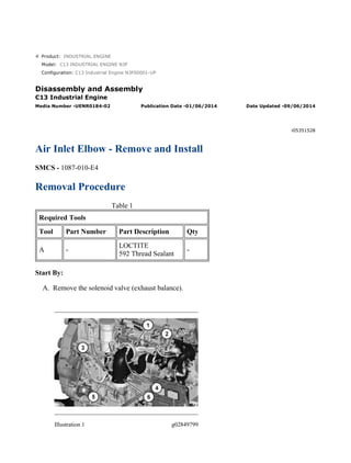
- 1. Product: INDUSTRIAL ENGINE Model: C13 INDUSTRIAL ENGINE N3F Configuration: C13 Industrial Engine N3F00001-UP Disassembly and Assembly C13 Industrial Engine Media Number -UENR0184-02 Publication Date -01/06/2014 Date Updated -09/06/2014 i05351528 Air Inlet Elbow - Remove and Install SMCS - 1087-010-E4 Removal Procedure Table 1 Required Tools Tool Part Number Part Description Qty A - LOCTITE 592 Thread Sealant - Start By: A. Remove the solenoid valve (exhaust balance). Illustration 1 g02849799 1/4(W) w 2022/3/19 https://127.0.0.1/sisweb/sisweb/techdoc/techdoc_print_page.jsp?returnurl=/sisweb/sisw...
- 2. 1. Disconnect the harness assembly from temperature sensor (5). Remove temperature sensor (5) . 2. Remove hose assembly (4) and the fittings. Remove clip (3) . 3. Loosen the clamps for hose (2) and remove hose (2) . 4. Loosen clamp (1) and remove air inlet elbow (6) . Illustration 2 g02849824 5. Disconnect the harness assembly from pressure sensor (7). Remove pressure sensor (7) . 6. Remove O-ring seal (8) and remove air inlet manifold (9). Remove and discard the gasket from air inlet manifold (9) . Illustration 3 g02849857 7. Remove bolts (11) and remove tube (10) and the O-ring seal. 2/4(W) w 2022/3/19 https://127.0.0.1/sisweb/sisweb/techdoc/techdoc_print_page.jsp?returnurl=/sisweb/sisw...
- 3. Illustration 4 g02849867 8. Remove pin spring (12) and dowel (14) . 9. Remove tube (14) and the wave ring. Illustration 5 g02849879 10. Remove plug (15) . Installation Procedure 1. Install air inlet elbow (6) in the reverse order of removal. a. Apply Tooling (A) to plug (15) . 3/4(W) w 2022/3/19 https://127.0.0.1/sisweb/sisweb/techdoc/techdoc_print_page.jsp?returnurl=/sisweb/sisw...
- 4. Illustration 6 g02849917 b. Install pin spring (12) to the depth illustrated by Dimension (B). Dimension (B) is 6.0 ± 0.50 mm (0.20 ± 0.020 inch). c. Install dowel (14) to the depth illustrated by Dimension (C). Dimension (C) is 2.9 mm (0.11 inch). d. Tighten pressure sensor (7) to a torque of 10 ± 2 N·m (89 ± 18 lb in). e. Tighten temperature sensor (5) to a torque of 20 ± 3 N·m (177 ± 27 lb in). f. Tighten clamp (1) to a torque of 8.5 ± 2 N·m (75 ± 18 lb in). 4/4(W) w 2022/3/19 https://127.0.0.1/sisweb/sisweb/techdoc/techdoc_print_page.jsp?returnurl=/sisweb/sisw...
- 5. Product: INDUSTRIAL ENGINE Model: C13 INDUSTRIAL ENGINE N3F Configuration: C13 Industrial Engine N3F00001-UP Disassembly and Assembly C13 Industrial Engine Media Number -UENR0184-02 Publication Date -01/06/2014 Date Updated -09/06/2014 i03537718 Inlet and Exhaust Valve Springs - Remove and Install SMCS - 1108-010 Removal Procedure Table 1 Required Tools Tool Part Number Part Description Qty A 235-0518 Valve Spring Compression Group 1 Start By: a. Remove the electronic unit injectors. Note: The following procedure is for the removal of the inlet valve springs and the exhaust valve springs without removing the cylinder head. This procedure can be performed on only one cylinder at a time. This will prevent the inlet valves and the exhaust valves from falling into the cylinder. 1. Rotate the crankshaft in order to bring the piston to the top center position in the cylinder. 1/3(W) w 2022/3/19 https://127.0.0.1/sisweb/sisweb/techdoc/techdoc_print_page.jsp?returnurl=/sisweb/sisw...
- 6. Illustration 1 g01136330 Personal injury can result from being struck by parts propelled by a released spring force. Make sure to wear all necessary protective equipment. Follow the recommended procedure and use all recommended tooling to release the spring force. 2. Install Tooling (A) on the cylinder head. 3. Remove retainer locks (1). 2/3(W) w 2022/3/19 https://127.0.0.1/sisweb/sisweb/techdoc/techdoc_print_page.jsp?returnurl=/sisweb/sisw...
- 7. 4. Remove Tooling (A). 5. Remove valve rotators (2). 6. Remove valve springs (3) and valve springs (4) from each valve. 7. Remove bases (5) from the cylinder head. Note: Install the valve springs before you rotate the crankshaft. Installation Procedure The valve keepers can be thrown from the valve when the valve spring compressor is released. Ensure that the valve keepers are properly installed on the valve stem. To help prevent personal injury, keep away from the front of the valve keepers and valve springs during the installation of the valves. Note: A small amount of grease can be used to hold the retainer locks in position during installation. Note: Lubricate the valve stems with clean engine oil. 1. Install valve springs (3) and (4) in reverse order of removal. 3/3(W) w 2022/3/19 https://127.0.0.1/sisweb/sisweb/techdoc/techdoc_print_page.jsp?returnurl=/sisweb/sisw...
- 8. Product: INDUSTRIAL ENGINE Model: C13 INDUSTRIAL ENGINE N3F Configuration: C13 Industrial Engine N3F00001-UP Disassembly and Assembly C13 Industrial Engine Media Number -UENR0184-02 Publication Date -01/06/2014 Date Updated -09/06/2014 i03538279 Inlet and Exhaust Valves - Remove and Install SMCS - 1105-010 Removal Procedure Table 1 Required Tools Tool Part Number Part Description Qty A 5S-1330 Valve Spring Compressor 1 Start By: a. Remove the cylinder head. 1/3(W) w 2022/3/19 https://127.0.0.1/sisweb/sisweb/techdoc/techdoc_print_page.jsp?returnurl=/sisweb/sisw...
- 9. Illustration 1 g01131781 Personal injury can result from being struck by parts propelled by a released spring force. Make sure to wear all necessary protective equipment. Follow the recommended procedure and use all recommended tooling to release the spring force. 1. Use Tooling (A) to remove retainer locks (1). 2. Remove valve rotators (2). 2/3(W) w 2022/3/19 https://127.0.0.1/sisweb/sisweb/techdoc/techdoc_print_page.jsp?returnurl=/sisweb/sisw...
- 10. 3. Remove valve springs (3) and valve springs (4). 4. Remove base (5). 5. Remove valves (6) from the cylinder head. 6. Remove valve seals (7). Installation Procedure The valve keepers can be thrown from the valve when the valve spring compressor is released. Ensure that the valve keepers are properly installed on the valve stem. To help prevent personal injury, keep away from the front of the valve keepers and valve springs during the installation of the valves. Note: A small amount of grease can be used to hold the retainer locks in position during installation. Note: Lubricate valves (6) with clean engine oil. 1. Install valves (6) in reverse order of removal. 3/3(W) w 2022/3/19 https://127.0.0.1/sisweb/sisweb/techdoc/techdoc_print_page.jsp?returnurl=/sisweb/sisw...
- 11. Product: INDUSTRIAL ENGINE Model: C13 INDUSTRIAL ENGINE N3F Configuration: C13 Industrial Engine N3F00001-UP Disassembly and Assembly C13 Industrial Engine Media Number -UENR0184-02 Publication Date -01/06/2014 Date Updated -09/06/2014 i05888682 Inlet and Exhaust Valve Guides - Remove and Install SMCS - 1104-010 Removal Procedure Table 1 Required Tools Tool Part Number Part Description Qty A 1U-9169 Valve Guide Driver 1 B 124-9057 Guide Collar 1 9U-6895 Valve Guide Driver 1 C(1) 455-0128 Seal Installer 1 375-2773 Seal Installer 1 (1) Use Seal Installer 455-0128 with Seal 163-2478. Use Seal Installer 375-2773 with Seal 361-3926. Start By: a. Remove the inlet valves and exhaust valves. 1/3(W) w 2022/3/19 https://127.0.0.1/sisweb/sisweb/techdoc/techdoc_print_page.jsp?returnurl=/sisweb/sisw...
- 12. Illustration 1 g03711984 1. Remove seals (1) from valve guides (2). Illustration 2 g03711987 2. Use Tooling (A) to remove the valve guides (2) from the cylinder head assembly. Installation Procedure Note: Lubricate the bores for the valve guides with clean engine oil. 1. Use Tooling (B) to install valve guides (2) in reverse order of removal. 2/3(W) w 2022/3/19 https://127.0.0.1/sisweb/sisweb/techdoc/techdoc_print_page.jsp?returnurl=/sisweb/sisw...
- 13. Illustration 3 g01301738 a. Install valve guides (1) until the protrusion is Dimension (X) above the cylinder head assembly. Dimension (X) is 20.0 ± 0.5 mm (0.79 ± 0.02 inch). b. Use Tooling (C) to install seals (1). 3/3(W) w 2022/3/19 https://127.0.0.1/sisweb/sisweb/techdoc/techdoc_print_page.jsp?returnurl=/sisweb/sisw...
- 14. Product: INDUSTRIAL ENGINE Model: C13 INDUSTRIAL ENGINE N3F Configuration: C13 Industrial Engine N3F00001-UP Disassembly and Assembly C13 Industrial Engine Media Number -UENR0184-02 Publication Date -01/06/2014 Date Updated -09/06/2014 i03538303 Inlet and Exhaust Valve Seat Inserts - Remove and Install SMCS - 1103-010 Removal Procedure Table 1 Required Tools Tool Part Number Part Description Qty A 166-7441 Valve Seat Extractor Tool 1 B 1U-9170 Valve Seat Driver 1 Start By: a. Remove the inlet and exhaust valves. 1/3(W) w 2022/3/19 https://127.0.0.1/sisweb/sisweb/techdoc/techdoc_print_page.jsp?returnurl=/sisweb/sisw...
- 15. Illustration 1 g01082582 1. Use Tooling (A) to remove valve seat inserts (1). Installation Procedure Illustration 2 g01079028 Note: Do not machine the prefinished valve seat inserts in order to correct the valve stem projection. An excessive valve stem projection indicates that the valve seat insert is not seated or material was not cleaned from the bottom of the counterbore. 1. Lower the temperature of new valve seat inserts (1). 2. Use Tooling (B) to install the new valve seat inserts (1) in reverse order of removal. 2/3(W) w 2022/3/19 https://127.0.0.1/sisweb/sisweb/techdoc/techdoc_print_page.jsp?returnurl=/sisweb/sisw...
- 16. Product: INDUSTRIAL ENGINE Model: C13 INDUSTRIAL ENGINE N3F Configuration: C13 Industrial Engine N3F00001-UP Disassembly and Assembly C13 Industrial Engine Media Number -UENR0184-02 Publication Date -01/06/2014 Date Updated -09/06/2014 i05351529 Engine Oil Filter Base - Remove and Install SMCS - 1306-010 Removal Procedure Table 1 Required Tools Tool Part Number Part Description Qty A 185-3630 Strap Wrench As 1 Illustration 1 g02174574 1. Refer to Operation and Maintenance Manual, "Engine Oil and Filter - Change" for the proper draining and filling procedures. 2. Disconnect tube assembly (3). Remove bolts (1 ) and elbow (2) . 1/5(W) w 2022/3/19 https://127.0.0.1/sisweb/sisweb/techdoc/techdoc_print_page.jsp?returnurl=/sisweb/sisw...
- 17. Illustration 2 g02174551 3. Remove bolts (4) and bolts (5). Remove manifold (6) and coupling (7) . Illustration 3 g01859093 4. Disconnect hose assembly (8). Remove hose assemblies (9). Remove bolts (10) and bolts (11). Remove oil filter base (12) and the O-ring seals. Illustration 4 g02850764 2/5(W) w 2022/3/19 https://127.0.0.1/sisweb/sisweb/techdoc/techdoc_print_page.jsp?returnurl=/sisweb/sisw...
- 18. Personal injury can result from being struck by parts propelled by a released spring force. Make sure to wear all necessary protective equipment. Follow the recommended procedure and use all recommended tooling to release the spring force. 5. Remove plug (15), spring (14), and plunger (13) from oil filter base (12) . Illustration 5 g02850770 Personal injury can result from being struck by parts propelled by a released spring force. Make sure to wear all necessary protective equipment. Follow the recommended procedure and use all recommended tooling to release the spring force. 6. Remove plug (18), spring assembly (17), and valve (16) from oil filter base (12) . 3/5(W) w 2022/3/19 https://127.0.0.1/sisweb/sisweb/techdoc/techdoc_print_page.jsp?returnurl=/sisweb/sisw...
- 19. Illustration 6 g02850774 Personal injury can result from being struck by parts propelled by a released spring force. Make sure to wear all necessary protective equipment. Follow the recommended procedure and use all recommended tooling to release the spring force. 7. Remove bolt (23), seat (22), spring (21), retainer (20), and spacer (19) from oil filter base (12) . Illustration 7 g02850818 8. Use Tooling (A) to remove oil filter (26) from remote engine oil filter base (25). Remove bolts (24) and remote engine oil filter base (25) . 4/5(W) w 2022/3/19 https://127.0.0.1/sisweb/sisweb/techdoc/techdoc_print_page.jsp?returnurl=/sisweb/sisw...
- 20. Illustration 8 g02850820 Personal injury can result from being struck by parts propelled by a released spring force. Make sure to wear all necessary protective equipment. Follow the recommended procedure and use all recommended tooling to release the spring force. 9. Remove plug (29), spring (28), and plunger (27) from remote engine oil filter base (25) . Installation Procedure 1. Install remote engine oil filter base (25) and oil filter base (12) in the reverse order of removal. a. Apply lubricant that is being sealed to all O-ring seals and the filters. b. Tighten plug (29) to a torque of 100 ± 15 N·m (74 ± 11 lb ft). c. Use Tooling (A) to tighten oil filter (26) to a torque of 65 ± 3 N·m (48 ± 2 lb ft). d. Tighten plug (18) to a torque of 100 ± 15 N·m (74 ± 11 lb ft). e. Tighten plug (15) to a torque of 100 ± 15 N·m (74 ± 11 lb ft). 5/5(W) w 2022/3/19 https://127.0.0.1/sisweb/sisweb/techdoc/techdoc_print_page.jsp?returnurl=/sisweb/sisw...
- 21. Product: INDUSTRIAL ENGINE Model: C13 INDUSTRIAL ENGINE N3F Configuration: C13 Industrial Engine N3F00001-UP Disassembly and Assembly C13 Industrial Engine Media Number -UENR0184-02 Publication Date -01/06/2014 Date Updated -09/06/2014 i03529781 Engine Oil Cooler - Remove and Install SMCS - 1378-010 Removal Procedure Start By: a. Remove the turbocharger 1. Refer to Operation and Maintenance Manual, "Cooling System Coolant (ELC) - Change" for the correct draining and filling procedures. Illustration 1 g02175060 2. Remove tube assemblies (1) and (2). 3. Remove clamps (3) and the hose. 4. Remove tube assembly (4). 5. Disconnect hose assembly (5). 1/2(W) w 2022/3/19 https://127.0.0.1/sisweb/sisweb/techdoc/techdoc_print_page.jsp?returnurl=/sisweb/sisw...
- 22. Suggest: For more complete manuals. Please go to the home page. https://www.ebooklibonline.com If the above button click is invalid. Please download this document first, and then click the above link to download the complete manual. Thank you so much for reading
- 23. Illustration 2 g01858607 6. Remove bolts (6). Remove engine oil cooler (7). Installation Procedure 1. Install engine oil cooler (7) in reverse order of removal. a. Tighten hose clamps (3) to a torque of 14 ± 1 N·m (124 ± 9 lb in). 2/2(W) w 2022/3/19 https://127.0.0.1/sisweb/sisweb/techdoc/techdoc_print_page.jsp?returnurl=/sisweb/sisw...
- 24. Product: INDUSTRIAL ENGINE Model: C13 INDUSTRIAL ENGINE N3F Configuration: C13 Industrial Engine N3F00001-UP Disassembly and Assembly C13 Industrial Engine Media Number -UENR0184-02 Publication Date -01/06/2014 Date Updated -09/06/2014 i06302536 Engine Oil Pump - Remove and Install SMCS - 1304-010 Removal Procedure 1. Drain the coolant from the cooling system into a suitable container for storage or for disposal. Refer to Operation and Maintenance Manual, "Cooling System Coolant (ELC) - Change". Illustration 1 g02174574 2. Remove bolts (1) and elbow (2) . 3. Disconnect hose assembly (3) . 1/2(W) w 2022/3/19 https://127.0.0.1/sisweb/sisweb/techdoc/techdoc_print_page.jsp?returnurl=/sisweb/sisw...