
Recommended
More Related Content
Similar to Caterpillar Cat D5R2 TRACK-TYPE TRACTOR (Prefix WRE) Service Repair Manual Instant Download (WRE00001 and up).pdf
Similar to Caterpillar Cat D5R2 TRACK-TYPE TRACTOR (Prefix WRE) Service Repair Manual Instant Download (WRE00001 and up).pdf (16)
More from ti76cui
More from ti76cui (20)
Recently uploaded
Recently uploaded (20)
Caterpillar Cat D5R2 TRACK-TYPE TRACTOR (Prefix WRE) Service Repair Manual Instant Download (WRE00001 and up).pdf
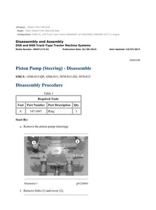
- 1. Product: TRACK-TYPE TRACTOR Model: D5R2 TRACK-TYPE TRACTOR WRE Configuration: D5R2 XL, LGP Track-Type Tractor WRE00001-UP (MACHINE) POWERED BY C7.1 Engine Disassembly and Assembly D5R and D6N Track-Type Tractor Machine Systems Media Number -M0071172-01 Publication Date -01/09/2015 Date Updated -10/07/2017 i06683286 Piston Pump (Steering) - Disassemble SMCS - 4306-015-QP; 4306-015; 5070-015-ZH; 5070-015 Disassembly Procedure Table 1 Required Tools Tool Part Number Part Description Qty A 147-3497 Ring 1 Start By: a. Remove the piston pump (steering). Illustration 1 g01226003 1. Remove bolts (1) and cover (2). 1/15 D5R2 XL, LGP Track-Type Tractor WRE00001-UP (MACHINE) POWERED BY C7... 2022/3/11 https://127.0.0.1/sisweb/sisweb/techdoc/techdoc_print_page.jsp?returnurl=/sis...
- 2. Illustration 2 g01226005 2. Remove gasket (3) and O-ring seal (4). Illustration 3 g01226006 3. Remove valve assembly (5). Illustration 4 g01226007 4. Remove gasket (6). 2/15 D5R2 XL, LGP Track-Type Tractor WRE00001-UP (MACHINE) POWERED BY C7... 2022/3/11 https://127.0.0.1/sisweb/sisweb/techdoc/techdoc_print_page.jsp?returnurl=/sis...
- 3. Illustration 5 g01226008 5. Remove cap (9), bolts (7), and valve (8). Illustration 6 g01226009 6. Remove O-ring seal (10), spring (11), O-ring seal (13), and spring (12), from valve assembly (5). Illustration 7 g01226010 7. Remove bolts (14) and pump (15). 3/15 D5R2 XL, LGP Track-Type Tractor WRE00001-UP (MACHINE) POWERED BY C7... 2022/3/11 https://127.0.0.1/sisweb/sisweb/techdoc/techdoc_print_page.jsp?returnurl=/sis...
- 4. Illustration 8 g06073965 8. Remove gasket (16). Illustration 9 g01226013 9. Remove O-ring seal (17), gear (19), and ring (18). Illustration 10 g01226014 10. Remove coupling (20), bolts (21), and head (22). 4/15 D5R2 XL, LGP Track-Type Tractor WRE00001-UP (MACHINE) POWERED BY C7... 2022/3/11 https://127.0.0.1/sisweb/sisweb/techdoc/techdoc_print_page.jsp?returnurl=/sis...
- 5. Illustration 11 g01226301 Improper assembly of parts that are spring loaded can cause bodily injury. To prevent possible injury, follow the established assembly procedure and wear protective equipment. 11. Remove cap (28), valve (23), O-ring seal (24), retainer (25), spring (26), and retainer (27). 12. Remove valve (29), O-ring seal (31), backup ring (30), retainer (33), and spring (32). 13. Repeat step 12p for valve (34). Illustration 12 g01226066 5/15 D5R2 XL, LGP Track-Type Tractor WRE00001-UP (MACHINE) POWERED BY C7... 2022/3/11 https://127.0.0.1/sisweb/sisweb/techdoc/techdoc_print_page.jsp?returnurl=/sis...
- 6. 14. Remove rotating group (36) from housing (35). Illustration 13 g01226064 15. Remove pistons (37), retainer (38), and bearing (39). Illustration 14 g01226063 16. Remove shims (40) from barrel assembly (41). 6/15 D5R2 XL, LGP Track-Type Tractor WRE00001-UP (MACHINE) POWERED BY C7... 2022/3/11 https://127.0.0.1/sisweb/sisweb/techdoc/techdoc_print_page.jsp?returnurl=/sis...
- 7. Illustration 15 g06074149 Improper assembly of parts that are spring loaded can cause bodily injury. To prevent possible injury, follow the established assembly procedure and wear protective equipment. 17. .Use a suitable press to remove retaining ring (42) from barrel assembly (41). Illustration 16 g01226061 18. Remove washer (45), spring (44), and washer (43) from barrel assembly (41). 7/15 D5R2 XL, LGP Track-Type Tractor WRE00001-UP (MACHINE) POWERED BY C7... 2022/3/11 https://127.0.0.1/sisweb/sisweb/techdoc/techdoc_print_page.jsp?returnurl=/sis...
- 8. Illustration 17 g01226060 19. Use Tooling (A) to remove retaining ring (46). Illustration 18 g01226058 20. Remove lip seal (47). Illustration 19 g01226017 8/15 D5R2 XL, LGP Track-Type Tractor WRE00001-UP (MACHINE) POWERED BY C7... 2022/3/11 https://127.0.0.1/sisweb/sisweb/techdoc/techdoc_print_page.jsp?returnurl=/sis...
- 9. 21. Remove retaining ring (48). Illustration 20 g01226019 22. Remove block (50), pin (51), bearing (52), pin (54), and bearing (53) from swashplate (49). Illustration 21 g01226315 23. Remove shaft (55). Illustration 22 g01226016 24. Use Tooling (A) to remove retaining ring (56). 9/15 D5R2 XL, LGP Track-Type Tractor WRE00001-UP (MACHINE) POWERED BY C7... 2022/3/11 https://127.0.0.1/sisweb/sisweb/techdoc/techdoc_print_page.jsp?returnurl=/sis...
- 10. 25. Remove bearing (57) from shaft (55). Illustration 23 g01226055 26. Remove pin (58), plug (59), and O-ring seal (60). Illustration 24 g01226057 27. Remove bearing races (62) and O-ring seal (61). 10/15 D5R2 XL, LGP Track-Type Tractor WRE00001-UP (MACHINE) POWERED BY ... 2022/3/11 https://127.0.0.1/sisweb/sisweb/techdoc/techdoc_print_page.jsp?returnurl=/sis...
- 11. Illustration 25 g01226054 28. Remove bolts (63) and piston assembly (64). Illustration 26 g01226067 29. Remove cap (65). Illustration 27 g01226053 30. Remove retaining ring (66). Illustration 28 g06074172 11/15 D5R2 XL, LGP Track-Type Tractor WRE00001-UP (MACHINE) POWERED BY ... 2022/3/11 https://127.0.0.1/sisweb/sisweb/techdoc/techdoc_print_page.jsp?returnurl=/sis...
- 12. Improper assembly of parts that are spring loaded can cause bodily injury. To prevent possible injury, follow the established assembly procedure and wear protective equipment. 31. Use Tooling (A) and a suitable press to remove keepers (67). Illustration 29 g01226050 32. Remove retainer (68), spring (69), spring (70), spring (71), and retainer (72). Illustration 30 g01226048 33. Remove nut (73) and cover (74). 12/15 D5R2 XL, LGP Track-Type Tractor WRE00001-UP (MACHINE) POWERED BY ... 2022/3/11 https://127.0.0.1/sisweb/sisweb/techdoc/techdoc_print_page.jsp?returnurl=/sis...
- 13. Illustration 31 g01226047 34. Remove O-ring seal (75). Illustration 32 g01226045 Improper assembly of parts that are spring loaded can cause bodily injury. To prevent possible injury, follow the established assembly procedure and wear protective equipment. 35. Use a suitable press and Tooling (C) to remove retaining ring (76). 13/15 D5R2 XL, LGP Track-Type Tractor WRE00001-UP (MACHINE) POWERED BY ... 2022/3/11 https://127.0.0.1/sisweb/sisweb/techdoc/techdoc_print_page.jsp?returnurl=/sis...
- 14. Illustration 33 g01226044 36. Remove washer (77), spacer (78), keeper (79), retainer (80), spring (81), spring (82), retainer (83), and spring (84) from rod (85). Illustration 34 g01226025 37. Remove bolts (86) and cover (87). Illustration 35 g01226023 38. Remove O-ring seal (88). 14/15 D5R2 XL, LGP Track-Type Tractor WRE00001-UP (MACHINE) POWERED BY ... 2022/3/11 https://127.0.0.1/sisweb/sisweb/techdoc/techdoc_print_page.jsp?returnurl=/sis...
- 15. Illustration 36 g01226022 39. Remove seals (89). 15/15 D5R2 XL, LGP Track-Type Tractor WRE00001-UP (MACHINE) POWERED BY ... 2022/3/11 https://127.0.0.1/sisweb/sisweb/techdoc/techdoc_print_page.jsp?returnurl=/sis...
- 16. Product: TRACK-TYPE TRACTOR Model: D5R2 TRACK-TYPE TRACTOR WRE Configuration: D5R2 XL, LGP Track-Type Tractor WRE00001-UP (MACHINE) POWERED BY C7.1 Engine Disassembly and Assembly D5R and D6N Track-Type Tractor Machine Systems Media Number -M0071172-01 Publication Date -01/09/2015 Date Updated -10/07/2017 i06682848 Piston Pump (Steering) - Assemble SMCS - 4306-016-QP; 4306-016; 5070-016-ZH; 5070-016 Assembly Procedure Table 1 Required Tools Tool Part Number Part Description Qty A 147-3497 Ring 1 Illustration 1 g01226022 1. Install seals (89). 1/16 D5R2 XL, LGP Track-Type Tractor WRE00001-UP (MACHINE) POWERED BY C7... 2022/3/11 https://127.0.0.1/sisweb/sisweb/techdoc/techdoc_print_page.jsp?returnurl=/sis...
- 17. Illustration 2 g01226023 2. Install O-ring seal (88). Illustration 3 g01226025 3. Install cover (87) and bolts (86). Illustration 4 g01226044 4. Install spring (84), retainer (83), spring (82), spring (81), retainer (80), keeper (79), spacer (78), and washer (77) onto rod (85). 2/16 D5R2 XL, LGP Track-Type Tractor WRE00001-UP (MACHINE) POWERED BY C7... 2022/3/11 https://127.0.0.1/sisweb/sisweb/techdoc/techdoc_print_page.jsp?returnurl=/sis...
- 18. Illustration 5 g01226045 Improper assembly of parts that are spring loaded can cause bodily injury. To prevent possible injury, follow the established assembly procedure and wear protective equipment. 5. Use a suitable press to install retaining ring (76). Illustration 6 g01226047 6. Install O-ring seal (75). 3/16 D5R2 XL, LGP Track-Type Tractor WRE00001-UP (MACHINE) POWERED BY C7... 2022/3/11 https://127.0.0.1/sisweb/sisweb/techdoc/techdoc_print_page.jsp?returnurl=/sis...
- 19. Illustration 7 g01226048 7. Install cover (74) and nut (73). Illustration 8 g01226050 8. Install retainer (72), spring (71), spring (70), spring (69), and retainer (68). Illustration 9 g06074172 4/16 D5R2 XL, LGP Track-Type Tractor WRE00001-UP (MACHINE) POWERED BY C7... 2022/3/11 https://127.0.0.1/sisweb/sisweb/techdoc/techdoc_print_page.jsp?returnurl=/sis...
- 20. Improper assembly of parts that are spring loaded can cause bodily injury. To prevent possible injury, follow the established assembly procedure and wear protective equipment. 9. Use Tooling (A) and a suitable press to install keepers (67). Illustration 10 g01226053 Improper assembly of parts that are spring loaded can cause bodily injury. To prevent possible injury, follow the established assembly procedure and wear protective equipment. 10. Use a suitable press to install retaining ring (66). Illustration 11 g01226067 5/16 D5R2 XL, LGP Track-Type Tractor WRE00001-UP (MACHINE) POWERED BY C7... 2022/3/11 https://127.0.0.1/sisweb/sisweb/techdoc/techdoc_print_page.jsp?returnurl=/sis...
- 21. 11. Install cap (65). Illustration 12 g01226054 12. Install piston assembly (64) and bolts (63). Illustration 13 g01226057 13. Install bearing races (62) and O-ring seal (61). 6/16 D5R2 XL, LGP Track-Type Tractor WRE00001-UP (MACHINE) POWERED BY C7... 2022/3/11 https://127.0.0.1/sisweb/sisweb/techdoc/techdoc_print_page.jsp?returnurl=/sis...
- 22. Illustration 14 g01226016 14. Install bearing (57) onto shaft (55). 15. Install retaining ring (56). Illustration 15 g01226315 16. Install shaft (55). Illustration 16 g01226019 17. Install bearing (53), pin (54), bearing (52), pin (51), and block (50) onto swashplate (49). 7/16 D5R2 XL, LGP Track-Type Tractor WRE00001-UP (MACHINE) POWERED BY C7... 2022/3/11 https://127.0.0.1/sisweb/sisweb/techdoc/techdoc_print_page.jsp?returnurl=/sis...
- 23. Illustration 17 g01226020 18. Install swashplate assembly (49). Illustration 18 g01226055 19. Install pin (58), O-ring seal (60), and plug (59). Illustration 19 g01226017 20. Install retaining ring (48). 8/16 D5R2 XL, LGP Track-Type Tractor WRE00001-UP (MACHINE) POWERED BY C7... 2022/3/11 https://127.0.0.1/sisweb/sisweb/techdoc/techdoc_print_page.jsp?returnurl=/sis...
- 24. Suggest: For more complete manuals. Please go to the home page. https://www.ebooklibonline.com If the above button click is invalid. Please download this document first, and then click the above link to download the complete manual. Thank you so much for reading
- 25. Illustration 20 g01226058 21. Install lip seal (47). Illustration 21 g01226060 22. Install retaining ring (46). Illustration 22 g01226061 9/16 D5R2 XL, LGP Track-Type Tractor WRE00001-UP (MACHINE) POWERED BY C7... 2022/3/11 https://127.0.0.1/sisweb/sisweb/techdoc/techdoc_print_page.jsp?returnurl=/sis...
- 26. 23. Install washer (43), spring (44), and washer (45) into barrel assembly (41). Illustration 23 g06074149 Improper assembly of parts that are spring loaded can cause bodily injury. To prevent possible injury, follow the established assembly procedure and wear protective equipment. 24. Use a suitable press to install retaining ring (42) into barrel assembly (41). Illustration 24 g01226063 25. Install shims (40) onto barrel assembly (41). 10/16 D5R2 XL, LGP Track-Type Tractor WRE00001-UP (MACHINE) POWERED BY ... 2022/3/11 https://127.0.0.1/sisweb/sisweb/techdoc/techdoc_print_page.jsp?returnurl=/sis...