
Recommended
Recommended
More Related Content
Similar to Caterpillar Cat 3512 Industrial Engine (Prefix SR2) Service Repair Manual Instant Download (SR200001 and up).pdf
Similar to Caterpillar Cat 3512 Industrial Engine (Prefix SR2) Service Repair Manual Instant Download (SR200001 and up).pdf (15)
More from ti76cui
More from ti76cui (20)
Recently uploaded
Recently uploaded (20)
Caterpillar Cat 3512 Industrial Engine (Prefix SR2) Service Repair Manual Instant Download (SR200001 and up).pdf
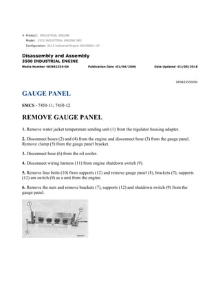
- 1. Product: INDUSTRIAL ENGINE Model: 3512 INDUSTRIAL ENGINE SR2 Configuration: 3512 Industrial Engine SR200001-UP Disassembly and Assembly 3500 INDUSTRIAL ENGINE Media Number -SENR2355-04 Publication Date -01/04/2006 Date Updated -01/05/2018 SENR23550004 GAUGE PANEL SMCS - 7450-11; 7450-12 REMOVE GAUGE PANEL 1. Remove water jacket temperature sending unit (1) from the regulator housing adapter. 2. Disconnect hoses (2) and (4) from the engine and disconnect hose (3) from the gauge panel. Remove clamp (5) from the gauge panel bracket. 3. Disconnect hose (6) from the oil cooler. 4. Disconnect wiring harness (11) from engine shutdown switch (9). 5. Remove four bolts (10) from supports (12) and remove gauge panel (8), brackets (7), supports (12) am switch (9) as a unit from the engine. 6. Remove the nuts and remove brackets (7), supports (12) and shutdown switch (9) from the gauge panel. 1/4(W) w 2022/5/11 https://127.0.0.1/sisweb/sisweb/techdoc/techdoc_print_page.jsp?returnurl=/sisweb/sisw...
- 2. 7. Put identification marks on hoses (2), (4) and (6) for correct installation, and remove the hoses from the gauges. 8. Remove the nuts and brackets (14) to remove the four gauges (13) from the front of panel (8). 2/4(W) w 2022/5/11 https://127.0.0.1/sisweb/sisweb/techdoc/techdoc_print_page.jsp?returnurl=/sisweb/sisw...
- 3. INSTALL GAUGE PANEL 1. Put the four gauges (1) in position in panel (2) and install brackets (3) and the nuts to hold the gauges in position. 2. Install hoses (4), (5) and (6) on the gauges. 3. Put brackets (7), supports (9) and engine shutdown switch (8) in position on the gauge panel and install the nuts to hold these in position. 4. Put gauge panel (2), brackets (7), supports (9) and the shutdown switch as a unit in position on the engine. Install the bolts to hold the unit in position. 5. Connect hose (5) to the oil cooler. 6. Install clamp (11) on the gauge panel bracket. Connect hose (10) to the gauge panel and connect hoses (4) and (6) to the engine. NOTE: Make sure the capillary tube from sending unit (12) does not make direct contact with the engine. 7. Install water jacket temperature sending unit (12) in the regulator housing adapter. 3/4(W) w 2022/5/11 https://127.0.0.1/sisweb/sisweb/techdoc/techdoc_print_page.jsp?returnurl=/sisweb/sisw...
- 5. Product: INDUSTRIAL ENGINE Model: 3512 INDUSTRIAL ENGINE SR2 Configuration: 3512 Industrial Engine SR200001-UP Disassembly and Assembly 3500 INDUSTRIAL ENGINE Media Number -SENR2355-04 Publication Date -01/04/2006 Date Updated -01/05/2018 SENR23550005 AIR INTAKE SHUTOFF (3508) SMCS - 1078-15; 1078-16; 1078-11; 1078-12 REMOVE AIR INTAKE SHUTOFF 1. Disconnect the harness assembly to the shutoff solenoid. 2. Remove the bolts to remove shield (1) and pipes (2) from the engine. 3. Remove the bolts and remove air intake cover (3) from the air shutoff group. 4. Remove bolts (5) and remove air shutoff group (4) from the aftercooler housings. 1/7(W) w 2022/5/11 https://127.0.0.1/sisweb/sisweb/techdoc/techdoc_print_page.jsp?returnurl=/sisweb/sisw...
- 6. INSTALL AIR INTAKE SHUTOFF 1. Put the gaskets and air shutoff group (1) in position on the aftercooler housings. Install the bolts to hold the group in position. 2. Put the gasket and air intake cover (2) in position on the air shutoff group. Install the bolts to hold cover (2) in position. 3. Put clean engine oil on the O-ring seals on pipes (4). Put pipes (4) and shield (3) in position on the engine and install the bolts to hold these in position. DISASSEMBLE AIR INTAKE SHUTOFF start by: a) remove air intake shutoff 2/7(W) w 2022/5/11 https://127.0.0.1/sisweb/sisweb/techdoc/techdoc_print_page.jsp?returnurl=/sisweb/sisw...
- 7. 1. Remove the bolts from solenoid (1). Hold handle (2) in the position as shown by hand or with a wrench and remove solenoid (1) from the air shutoff group. Slowly release handle (2) to the shutoff position. 2. Bend the locks away from bolts (3) and loosen all of the bolts (3) that hold the plate assemblies to the shaft assembly. 3. Move handle (2) back to the position as shown by hand or with a wrench and put solenoid (1) in position in the shutoff housing assembly. Install the bolts and release the handle. 4. Remove the bolts, the locks, the plates and bushing from plate assemblies (4). Remove plate assemblies (4) from the shaft assembly. 5. Do Step 1 again to remove solenoid (1). 6. Remove the bolt and remove handle (2) from the shaft assembly. 7. Remove the bolts and remove cover assembly (5) from the housing assembly. 8. Remove seal (6) from cover assembly (5). 9. Remove pin (8) to remove spacer assembly (7) from the housing assembly. 3/7(W) w 2022/5/11 https://127.0.0.1/sisweb/sisweb/techdoc/techdoc_print_page.jsp?returnurl=/sisweb/sisw...
- 8. 10. Remove shaft assembly (9), the spacer and spring from the housing assembly. Remove the spring and spacer from the shaft assembly. 11. If necessary, remove the dowel and remove lever (10), spacer assembly (12) and pin (11) as a unit from shaft assembly (9). Remove pin (11) from lever (10) to remove spacer assembly (12) from lever (10) if necessary. 4/7(W) w 2022/5/11 https://127.0.0.1/sisweb/sisweb/techdoc/techdoc_print_page.jsp?returnurl=/sisweb/sisw...
- 9. ASSEMBLE AIR INTAKE SHUTOFF 1. If necessary, make a replacement of dowel (1) and make sure the end of the dowel as shown is 83.0 ± 0.5 mm (3.268 ± .020 in) below surface (X). 2. If shaft assembly (2) was disassembled, put spacer assembly (5) in position on lever (3) and use a press to install pin (4) until it is even (flush) with the surface of lever (3) as shown. Put lever (3), spacer assembly (5) and pin (4) as a unit in position on shaft assembly (2). Install the dowel to hold the unit on shaft assembly (2) and put marks (stake) the end of the dowel. 3. Install spacer (8) and spring (6) on shaft assembly (2). Install shaft assembly (2) in housing assembly (7). Make sure spring (6) is correctly engaged with dowel (1) as shown. 4. Install handle (10) on the shaft assembly. Turn handle (10) up (upward) and install pin (11) so handle (10) can be put in contact with pin (11). With handle (10) in contact with pin (11), install plate assemblies (9) on the shaft assembly. 5. Release handle (10) from the pin and remove the pin so plate assemblies (9) can move to the "SHUTOFF" position. A 0.076 mm (.003 in) feeler gauge must not pass between plate assembles (9) and the housing assembly as shown. Remove handle (10) from the shaft assembly. 5/7(W) w 2022/5/11 https://127.0.0.1/sisweb/sisweb/techdoc/techdoc_print_page.jsp?returnurl=/sisweb/sisw...
- 10. 6. Put spacer assembly (12) in position and install pin (11) in the housing assembly through the spacer assembly. 7. Use tool group (A) to install the seal until it is even (flush) with the inside surface of cover assembly (13). Make sure the lip of the seal is toward the outside surface of the cover as shown. 8. Install cover assembly (13) on the housing assembly and the bolts to hold it. 9. Install handle (10) on the shaft assembly and the bolts to hold it. NOTE: To make the installation of the bolts in the air shutoff group easier, the electric solenoid must be installed before the air shutoff group is installed on the engine. 10. Turn handle (10) to the open position as shown and put the gasket and solenoid (14) in position on the housing assembly. Release the handle and install the bolts to hold the solenoid in position. end by: 6/7(W) w 2022/5/11 https://127.0.0.1/sisweb/sisweb/techdoc/techdoc_print_page.jsp?returnurl=/sisweb/sisw...
- 11. a) install air intake shutoff 7/7(W) w 2022/5/11 https://127.0.0.1/sisweb/sisweb/techdoc/techdoc_print_page.jsp?returnurl=/sisweb/sisw...
- 12. Product: INDUSTRIAL ENGINE Model: 3512 INDUSTRIAL ENGINE SR2 Configuration: 3512 Industrial Engine SR200001-UP Disassembly and Assembly 3500 INDUSTRIAL ENGINE Media Number -SENR2355-04 Publication Date -01/04/2006 Date Updated -01/05/2018 SENR23550006 AIR INTAKE SHUTOFF (3512) SMCS - 1078-16; 1078-11; 1078-12; 1078-15 REMOVE AIR INTAKE SHUTOFF 1. Remove shield (3) from the shutoff housing. 2. Turn of the air supply to the engine. 3. Disconnect tube assemblies (1) and remove bolts (2). Remove air shutoff cylinder (4) and the flange from the shutoff housing. 4. Remove pipes (5) from the turbocharges and shutoff housing. 5. Remove the bolts and remove air intake shutoff (6) from the engine. 1/6(W) w 2022/5/11 https://127.0.0.1/sisweb/sisweb/techdoc/techdoc_print_page.jsp?returnurl=/sisweb/sisw...
- 13. INSTALL AIR INTAKE SHUTOFF 1. Put the gasket and air intake shutoff (1) in position and install the bolts that hold it in position. 2. Make sure the O-ring seals, the flanges and the gaskets are in position on pipes (2). Install pipes (2) between the turbochargers and shutoff housing. 3. Install the flange, shutoff cylinder (5) and shield (4) on the shutoff housing. 4. Connect tube assemblies (3) to the shutoff cylinder and open the air supply to the engine. DISASSEMBLE AIR INTAKE SHUTOFF start by: a) remove air intake shutoff 2/6(W) w 2022/5/11 https://127.0.0.1/sisweb/sisweb/techdoc/techdoc_print_page.jsp?returnurl=/sisweb/sisw...
- 14. 1. Remove the four bolts (1) to remove the spring and valve assembly (2) from the shaft. 2. Remove the bolts and nuts to remove valve assembly (2) from spring (3). 3. Remove the bolts and remove arm (4) and latch (5) from the shaft. 4. Remove the two bolts (6) and the washers to remove knob (7), the cover and shaft from the shutoff housing. 5. Remove bolt (10) and the washer to remove knob (7) and cover (9) from shaft (8). 6. Remove carrier (12) from the shutoff housing (11). 7. Remove plug (14), the spring and pin from carrier (2). 8. Remove seal (13) from the shutoff housing. If necessary, remove bushings (15) for shaft (8) from the housing. 3/6(W) w 2022/5/11 https://127.0.0.1/sisweb/sisweb/techdoc/techdoc_print_page.jsp?returnurl=/sisweb/sisw...
- 15. ASSEMBLE AIR INTAKE SHUTOFF 1. Use tooling (A) to install the bushings and seal in the shutoff housing. Install the seal with the lip of the seal toward the inside of the housing as shown. Check the inside diameter dimension of the bearings after installation. The correct dimension is 19.050 ± 0.044 mm (.750 ± .002 in). 2. Install the pin, the spring and plug (2) in carrier (1). 3. Install carrier (1) in the shutoff housing and tighten the carrier to a torque of 120 ± 15 N·m (90 ± 11 lb ft). 4. Put cover (4) and knob (5) on shaft (3) and install the bolt and washer to hold knob (5) on shaft (3). 5. Put shaft (3) in position through the seal in the shutoff housing and put bushing (7) and spring (6) over the end of the shaft. 6. Push the shaft all the way in the housing and install the bolts and washers to hold cover (4) in position. 4/6(W) w 2022/5/11 https://127.0.0.1/sisweb/sisweb/techdoc/techdoc_print_page.jsp?returnurl=/sisweb/sisw...
- 16. 7. Make sure the end of spring (6) is engaged with the hole in the shutoff housing and install latch (9) to connect spring (6) to the shaft. Install arm (8) on the shaft. 8. Put valve assembly (11) in position on spring (10) and install the bolts, washers and nuts to hold the unit together. 9. Put spring (10) and valve assembly (11) in position and install the bolts and washer to hold the unit to shaft (3). end by: a) install air intake shutoff 5/6(W) w 2022/5/11 https://127.0.0.1/sisweb/sisweb/techdoc/techdoc_print_page.jsp?returnurl=/sisweb/sisw...
- 18. Suggest: For more complete manuals. Please go to the home page. https://www.ebooklibonline.com If the above button click is invalid. Please download this document first, and then click the above link to download the complete manual. Thank you so much for reading
- 19. Product: INDUSTRIAL ENGINE Model: 3512 INDUSTRIAL ENGINE SR2 Configuration: 3512 Industrial Engine SR200001-UP Disassembly and Assembly 3500 INDUSTRIAL ENGINE Media Number -SENR2355-04 Publication Date -01/04/2006 Date Updated -01/05/2018 SENR23550007 PISTON COOLING JETS, SERVICE METER SMCS - 1307-10; 7478-10 REMOVE AND INSTALL PISTON COOLING JETS 1. Remove the cover from side of the engine block. 2. Remove bolts (1) and retainer (2). 3. Pull cooling jet (3) out of its bore in the engine block from the inside to remove it. 4. Put cooling jet (3) in position in the engine block. Make sure the oil holes in the end of the jet are toward the piston. 5. Install retainer (2) and bolts (1) to hold jet (3) in position. 6. Install the cover on the side of the engine block. 1/2(W) w 2022/5/11 https://127.0.0.1/sisweb/sisweb/techdoc/techdoc_print_page.jsp?returnurl=/sisweb/sisw...
- 20. REMOVE AND INSTALL SERVICE METER 1. Remove bolts (2) and the clamps to remove service meter (1) from the tachometer drive adapter assembly. 2. Put clean engine oil on O-ring seal (3) and install service meter (1) in the tachometer drive adapter assembly. Make sure the shaft of the service meter engages in the groove (slot) in the shaft of the tachometer drive. 3. Install bolts (2) and the clamps to hold the service meter in position. 2/2(W) w 2022/5/11 https://127.0.0.1/sisweb/sisweb/techdoc/techdoc_print_page.jsp?returnurl=/sisweb/sisw...