Downloaded 150 times
![108 Solutions Manual • Instructor’s Solution Manual to Accompany Mechanical Engineering Design
Then
k =
F
δ
=
π Er1(r1 + l tan α)
l
=
E A1
l
1 +
2l
d1
tan α Ans.
5-6
F = (T + dT) + w dx − T = 0
dT
dx
= −w
Solution is T = −wx + c
T|x=0 = P + wl = c
T = −wx + P + wl
T = P + w(l − x)
The infinitesmal stretch of the free body of original length dx is
dδ =
Tdx
AE
=
P + w(l − x)
AE
dx
Integrating,
δ =
l
0
[P + w(l − x)] dx
AE
δ =
Pl
AE
+
wl2
2AE
Ans.
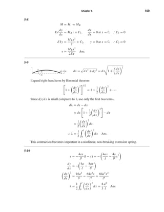
5-7
M = wlx −
wl2
2
−
wx2
2
E I
dy
dx
=
wlx2
2
−
wl2
2
x −
wx3
6
+ C1,
dy
dx
= 0 at x = 0, ІC1 = 0
E I y =
wlx3
6
−
wl2
x2
4
−
wx4
24
+ C2, y = 0 at x = 0, ІC2 = 0
y =
wx2
24E I
(4lx − 6l2
− x2
) Ans.
l
x
dx
P
Enlarged free
body of length dx
w is cable’s weight
per foot
T ϩ dT
wdx
T
shi20396_ch05.qxd 8/18/03 10:59 AM Page 108](https://image.slidesharecdn.com/captulo05-deflexoerigidez-140621145643-phpapp01/85/Capitulo-05-deflexao-e-rigidez-3-320.jpg)
![110 Solutions Manual • Instructor’s Solution Manual to Accompany Mechanical Engineering Design
5-11
y = a sin
πx
l
dy
dx
=
aπ
l
cos
πx
l
dy
dx
2
=
a2
π2
l2
cos2 πx
l
λ =
1
2
l
0
dy
dx
2
dx
λ =
π2
4
a2
l
= 2.467
a2
l
Ans.
Compare result with that of Prob. 5-10. See Charles R. Mischke, Elements of Mechanical
Analysis,Addison-Wesley, Reading, Mass., 1963, pp. 244–249, for application to a nonlinear
extension spring.
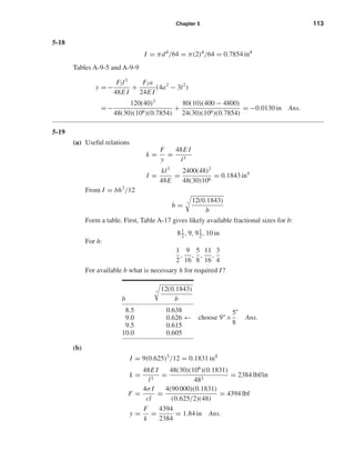
5-12
I = 2(5.56) = 11.12 in4
ymax = y1 + y2 = −
wl4
8E I
+
Fa2
6E I
(a − 3l)
Here w = 50/12 = 4.167 lbf/in, and a = 7(12) = 84 in, and l = 10(12) = 120 in.
y1 = −
4.167(120)4
8(30)(106)(11.12)
= −0.324 in
y2 = −
600(84)2
[3(120) − 84]
6(30)(106)(11.12)
= −0.584 in
So ymax = −0.324 − 0.584 = −0.908 in Ans.
M0 = −Fa − (wl2
/2)
= −600(84) − [4.167(120)2
/2]
= −80 400 lbf · in
c = 4 − 1.18 = 2.82 in
σmax =
−My
I
= −
(−80 400)(−2.82)
11.12
(10−3
)
= −20.4 kpsi Ans.
σmax is at the bottom of the section.
shi20396_ch05.qxd 8/18/03 10:59 AM Page 110](https://image.slidesharecdn.com/captulo05-deflexoerigidez-140621145643-phpapp01/85/Capitulo-05-deflexao-e-rigidez-5-320.jpg)
![Chapter 5 111
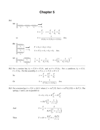
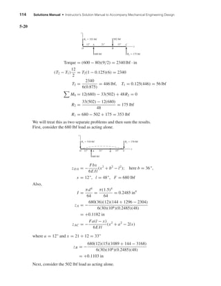
5-13
RO =
7
10
(800) +
5
10
(600) = 860 lbf
RC =
3
10
(800) +
5
10
(600) = 540 lbf
M1 = 860(3)(12) = 30.96(103
) lbf · in
M2 = 30.96(103
) + 60(2)(12)
= 32.40(103
) lbf · in
σmax =
Mmax
Z
⇒ 6 =
32.40
Z
Z = 5.4 in3
y|x=5ft =
F1a[l − (l/2)]
6E Il
l
2
2
+ a2
− 2l
l
2
−
F2l3
48E I
−
1
16
=
800(36)(60)
6(30)(106)I (120)
[602
+ 362
− 1202
] −
600(1203
)
48(30)(106)I
I = 23.69 in4
⇒ I/2 = 11.84 in4
Select two 6 in-8.2 lbf/ft channels; from TableA-7, I = 2(13.1) = 26.2 in4
, Z = 2(4.38) in3
ymax =
23.69
26.2
−
1
16
= −0.0565 in
σmax =
32.40
2(4.38)
= 3.70 kpsi
5-14
I =
π
64
(1.54
) = 0.2485 in4
Superpose beams A-9-6 and A-9-7,
yA =
300(24)(16)
6(30)(106)(0.2485)(40)
(162
+ 242
− 402
)
+
12(16)
24(30)(106)(0.2485)
[2(40)(162
) − 163
− 403
]
yA = −0.1006 in Ans.
y|x=20 =
300(16)(20)
6(30)(106)(0.2485)(40)
[202
+ 162
− 2(40)(20)]
−
5(12)(404)
384(30)(106)(0.2485)
= −0.1043 in Ans.
% difference =
0.1043 − 0.1006
0.1006
(100) = 3.79% Ans.
RC
M1 M2
RO
A
O
B
C
V (lbf)
M
(lbf•in)
800 lbf 600 lbf
3 ft
860
60
O
Ϫ540
2 ft 5 ft
shi20396_ch05.qxd 8/18/03 10:59 AM Page 111](https://image.slidesharecdn.com/captulo05-deflexoerigidez-140621145643-phpapp01/85/Capitulo-05-deflexao-e-rigidez-6-320.jpg)
![112 Solutions Manual • Instructor’s Solution Manual to Accompany Mechanical Engineering Design
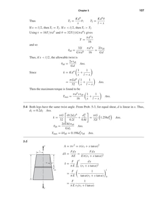
5-15
I =
1
12
3
8
(1.53
) = 0.105 47 in4
From Table A-9-10
yC = −
Fa2
3E I
(l + a)
dyAB
dx
=
Fa
6E Il
(l2
− 3x2
)
Thus,
θA =
Fal2
6E Il
=
Fal
6E I
yD = −θAa = −
Fa2
l
6E I
With both loads,
yD = −
Fa2
l
6E I
−
Fa2
3E I
(l + a)
= −
Fa2
6E I
(3l + 2a) = −
120(102
)
6(30)(106)(0.105 47)
[3(20) + 2(10)]
= −0.050 57 in Ans.
yE =
2Fa(l/2)
6E Il
l2
−
l
2
2
=
3
24
Fal2
E I
=
3
24
120(10)(202
)
(30)(106)(0.105 47)
= 0.018 96 in Ans.
5-16 a = 36 in, l = 72 in, I = 13 in4
, E = 30 Mpsi
y =
F1a2
6E I
(a − 3l) −
F2l3
3E I
=
400(36)2
(36 − 216)
6(30)(106)(13)
−
400(72)3
3(30)(106)(13)
= −0.1675 in Ans.
5-17 I = 2(1.85) = 3.7 in4
Adding the weight of the channels, 2(5)/12 = 0.833 lbf/in,
yA = −
wl4
8E I
−
Fl3
3E I
= −
10.833(484)
8(30)(106)(3.7)
−
220(483)
3(30)(106)(3.7)
= −0.1378 in Ans.
A
a
D C
F
B a
EA
shi20396_ch05.qxd 8/18/03 10:59 AM Page 112](https://image.slidesharecdn.com/captulo05-deflexoerigidez-140621145643-phpapp01/85/Capitulo-05-deflexao-e-rigidez-7-320.jpg)
![116 Solutions Manual • Instructor’s Solution Manual to Accompany Mechanical Engineering Design
Adding the two deflections,
yC = −0.057 52 − 0.1923 = −0.2498 in Ans.
(b) At O:
Due to 450 lbf:
dy
dx x=0
=
Fa
6E Il
(l2
− 3x2
)
x=0
=
Fal
6E I
θO = −
720(11)(0 + 112
− 400)
6(30)(106)(0.1198)(20)
+
450(12)(20)
6(30)(106)(0.1198)
= 0.010 13 rad = 0.5805◦
At B:
θB = −4.793(10−3
) +
450(12)
6(30)(106)(0.1198)(20)
[202
− 3(202
)]
= −0.014 81 rad = 0.8485◦
I = 0.1198
0.8485◦
0.06◦
= 1.694 in4
d =
64I
π
1/4
=
64(1.694)
π
1/4
= 2.424 in
Use d = 2.5 in Ans.
I =
π
64
(2.54
) = 1.917 in4
yC = −0.2498
0.1198
1.917
= −0.015 61 in Ans.
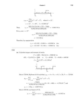
5-22
(a) l = 36(12) = 432 in
ymax = −
5wl4
384E I
= −
5(5000/12)(432)4
384(30)(106)(5450)
= −1.16 in
The frame is bowed up 1.16 in with respect to the bolsters. It is fabricated upside down
and then inverted. Ans.
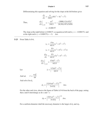
(b) The equation in xy-coordinates is for the center sill neutral surface
y =
wx
24E I
(2lx2
− x3
− l3
) Ans.
y
x
l
shi20396_ch05.qxd 8/18/03 10:59 AM Page 116](https://image.slidesharecdn.com/captulo05-deflexoerigidez-140621145643-phpapp01/85/Capitulo-05-deflexao-e-rigidez-11-320.jpg)

= −0.0606 mm Ans.
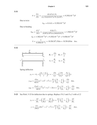
5-26
x
y
z
F1
a2
b2
b1
a1
F2
3.5 kN
100
250
150
d
The slope at x = 0 due to F1 in the xy plane is
θxy =
F1b1 b2
1 − l2
6E Il
and in the xz plane due to F2 is
θxz =
F2b2 b2
2 − l2
6E Il
For small angles, the slopes add as vectors. Thus
θL = θ2
xy + θ2
xz
1/2
=
F1b1 b2
1 − l2
6E Il
2
+
F2b2 b2
2 − l2
6E Il
2
1/2
shi20396_ch05.qxd 8/18/03 10:59 AM Page 118](https://image.slidesharecdn.com/captulo05-deflexoerigidez-140621145643-phpapp01/85/Capitulo-05-deflexao-e-rigidez-13-320.jpg)
![Chapter 5 119
Designating the slope constraint as ξ, we then have
ξ = |θL| =
1
6E Il
Fi bi b2
i − l2 2 1/2
Setting I = πd4
/64 and solving for d
d =
32
3π Elξ
Fi bi b2
i − l2 2 1/2 1/4
For the LH bearing, E = 30 Mpsi, ξ = 0.001, b1 = 12, b2 = 6, and l = 16. The result is
dL =1.31 in. Using a similar flip beam procedure, we get dR = 1.36 in for the RH bearing.
So use d = 1 3/8 in Ans.
5-27 For the xy plane, use yBC of Table A-9-6
y =
100(4)(16 − 8)
6(30)(106)(16)
[82
+ 42
− 2(16)8] = −1.956(10−4
) in
For the xz plane use yAB
z =
300(6)(8)
6(30)(106)(16)
[82
+ 62
− 162
] = −7.8(10−4
) in
δ = (−1.956j − 7.8k)(10−4
) in
|δ| = 8.04(10−4
) in Ans.
5-28
dL =
32n
3π Elξ
Fi bi b2
i − l2 2 1/2 1/4
=
32(1.5)
3π(29.8)(106)(10)(0.001)
[800(6)(62
− 102
)]2
+ [600(3)(32
− 102
)]2 1/2
1/4
= 1.56 in
dR =
32(1.5)
3π(29.8)(106)(10)(0.001)
[800(4)(102
− 42
)]2
+ [600(7)(102
− 72
)]2 1/2
1/4
= 1.56 in choose d ≥ 1.56 in Ans.
5-29 From Table A-9-8 we have
yL =
MB x
6E Il
(x2
+ 3a2
− 6al + 2l2
)
dyL
dx
=
MB
6E Il
(3x2
+ 3a2
− 6al + 2l2
)
shi20396_ch05.qxd 8/18/03 10:59 AM Page 119](https://image.slidesharecdn.com/captulo05-deflexoerigidez-140621145643-phpapp01/85/Capitulo-05-deflexao-e-rigidez-14-320.jpg)
![120 Solutions Manual • Instructor’s Solution Manual to Accompany Mechanical Engineering Design
At x = 0, the LH slope is
θL =
dyL
dx
=
MB
6E Il
(3a2
− 6al + 2l2
)
from which
ξ = |θL| =
MB
6E Il
(l2
− 3b2
)
Setting I = πd4
/64 and solving for d
d =
32MB(l2
− 3b2
)
3π Elξ
1/4
For a multiplicity of moments, the slopes add vectorially and
dL =
32
3π Elξ
Mi l2
− 3b2
i
2 1/2 1/4
dR =
32
3π Elξ
Mi 3a2
i − l2 2 1/2 1/4
The greatest slope is at the LH bearing. So
d =
32(1200)[92
− 3(42
)]
3π(30)(106)(9)(0.002)
1/4
= 0.706 in
So use d = 3/4 in Ans.
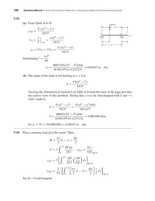
5-30
6FAC = 18(80)
FAC = 240 lbf
RO = 160 lbf
I =
1
12
(0.25)(23
) = 0.1667 in4
Initially, ignore the stretch of AC. From Table A-9-10
yB1 = −
Fa2
3E I
(l + a) = −
80(122
)
3(10)(106)(0.1667)
(6 + 12) = −0.041 47 in
Stretch of AC: δ =
FL
AE AC
=
240(12)
(π/4)(1/2)2
(10)(106)
= 1.4668(10−3
) in
Due to stretch of AC
By superposition,
yB2 = −3δ = −4.400(10−3
) in
yB = −0.041 47 − 0.0044 = −0.045 87 in Ans.
80 lbfFAC
126
B
RO
shi20396_ch05.qxd 8/18/03 10:59 AM Page 120](https://image.slidesharecdn.com/captulo05-deflexoerigidez-140621145643-phpapp01/85/Capitulo-05-deflexao-e-rigidez-15-320.jpg)
![122 Solutions Manual • Instructor’s Solution Manual to Accompany Mechanical Engineering Design
5-34 Let the load be at x > l/2. The maximum deflection will be in Section AB (Table A-9-10)
yAB =
Fbx
6E Il
(x2
+ b2
− l2
)
dyAB
dx
=
Fb
6E Il
(3x2
+ b2
− l2
) = 0 ⇒ 3x2
+ b2
− l2
= 0
x =
l2 − b2
3
, xmax =
l2
3
= 0.577l Ans.
For x < l/2 xmin = l − 0.577l = 0.423l Ans.
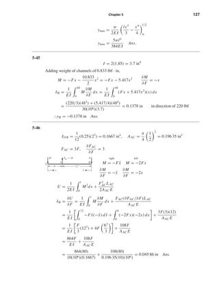
5-35
MO = 50(10)(60) + 600(84)
= 80 400 lbf · in
RO = 50(10) + 600 = 1100 lbf
I = 11.12 in4
from Prob. 5-12
M = −80 400 + 1100x −
4.167x2
2
− 600 x − 84 1
E I
dy
dx
= −80 400x + 550x2
− 0.6944x3
− 300 x − 84 2
+ C1
dy
dx
= 0 at x = 0 І C1 = 0
E I y = −402 00x2
+ 183.33x3
− 0.1736x4
− 100 x − 84 3
+ C2
y = 0 at x = 0 І C2 = 0
yB =
1
30(106)(11.12)
[−40 200(1202
) + 183.33(1203
)
− 0.1736(1204
) − 100(120 − 84)3
]
= −0.9075 in Ans.
5-36 See Prob. 5-13 for reactions: RO = 860 lbf, RC = 540 lbf
M = 860x − 800 x − 36 1
− 600 x − 60 1
E I
dy
dx
= 430x2
− 400 x − 36 2
− 300 x − 60 2
+ C1
E I y = 143.33x3
− 133.33 x − 36 3
− 100 x − 60 3
+ C1x + C2
y = 0 at x = 0 ⇒ C2 = 0
y = 0 at x = 120 in ⇒ C1 = −1.2254(106
) lbf · in2
Substituting C1 and C2 and evaluating at x = 60,
E I y = 30(106
)I −
1
16
= 143.33(603
) − 133.33(60 − 36)3
− 1.2254(106
)(60)
I = 23.68 in4
Agrees with Prob. 5-13. The rest of the solution is the same.
10'
7'
RO
600 lbf50 lbf/ft
MO
O
A
B
shi20396_ch05.qxd 8/18/03 10:59 AM Page 122](https://image.slidesharecdn.com/captulo05-deflexoerigidez-140621145643-phpapp01/85/Capitulo-05-deflexao-e-rigidez-17-320.jpg)
![Chapter 5 123
5-37
I = 0.2485 in4
RO = 12(20) +
24
40
(300) = 420 lbf
M = 420x −
12
2
x2
− 300 x − 16 1
E I
dy
dx
= 210x2
− 2x3
− 150 x − 16 2
+ C1
E I y = 70x3
− 0.5x4
− 50 x − 16 3
+ C1x + C2
y = 0 at x = 0 ⇒ C2 = 0
y = 0 at x = 40 in ⇒ C1 = −6.272(104
) lbf · in2
Substituting for C1 and C2 and evaluating at x = 16,
yA =
1
30(106)(0.2485)
[70(163
) − 0.5(164
) − 6.272(104
)(16)]
= −0.1006 in Ans.
y|x=20 =
1
30(106)(0.2485)
[70(203
) − 0.5(204
) − 50(20 − 16)3
− 6.272(104
)(20)]
= 0.1043 in Ans.
3.7% difference Ans.
5-38
R1 =
w[(l + a)/2][(l − a)/2)]
l
=
w
4l
(l2
− a2
)
R2 =
w
2
(l + a) −
w
4l
(l2
− a2
) =
w
4l
(l + a)2
M =
w
4l
(l2
− a2
)x −
wx2
2
+
w
4l
(l + a)2
x − l 1
E I
dy
dx
=
w
8l
(l2
− a2
)x2
−
w
6
x3
+
w
8l
(l + a)2
x − l 2
+ C1
E I y =
w
24l
(l2
− a2
)x3
−
w
24
x4
+
w
24l
(l + a)2
x − l 3
+ C1x + C2
y = 0 at x = 0 ⇒ C2 = 0
y = 0 at x = l
0 =
w
24l
(l2
− a2
)l3
−
w
24
l4
+ C1l ⇒ C1 =
wa2
l
24
y =
w
24E Il
[(l2
− a2
)x3
− lx4
+ (l + a)2
x − l 3
+ a2
l2
x] Ans.
a
w
l ϩ a
2
l Ϫ a
2
shi20396_ch05.qxd 8/18/03 10:59 AM Page 123](https://image.slidesharecdn.com/captulo05-deflexoerigidez-140621145643-phpapp01/85/Capitulo-05-deflexao-e-rigidez-18-320.jpg)
![124 Solutions Manual • Instructor’s Solution Manual to Accompany Mechanical Engineering Design
5-39 From Prob. 5-15, RA = RB = 120 lbf, and I = 0.105 47 in4
First half of beam,
M = −120x + 120 x − 10 1
E I
dy
dx
= −60x2
+ 60 x − 10 2
+ C1
dy/dx = 0 at x = 20 in ⇒ 0 = −60(202
) + 60(20 −10)2
+ C1 ⇒ C1 = 1.8(104
) lbf · in2
E I y = −20x3
+ 20 x − 10 3
+ 1.8(104
)x + C2
y = 0 at x = 10 in ⇒ C2 = −1.6(105
) lbf · in3
y|x=0 =
1
30(106)(0.105 47)
(−1.6)(105
)
= −0.050 57 in Ans.
y|x=20 =
1
30(106)(0.105 47)
[−20(203
) + 20(20 − 10)3
+ 1.8(104
)(20) − 1.6(105
)]
= 0.018 96 in Ans.
5-40 From Prob. 5-30, RO = 160 lbf ↓, FAC = 240 lbf I = 0.1667 in4
M = −160x + 240 x − 6 1
E I
dy
dx
= −80x2
+ 120 x − 6 2
+ C1
E I y = −26.67x3
+ 40 x − 6 3
+ C1x + C2
y = 0 at x = 0 ⇒ C2 = 0
yA = −
FL
AE AC
= −
240(12)
(π/4)(1/2)2(10)(106)
= −1.4668(10−3
) in
at x = 6
10(106
)(0.1667)(−1.4668)(10−3
) = −26.67(63
) + C1(6)
C1 = 552.58 lbf · in2
yB =
1
10(106)(0.1667)
[−26.67(183
) + 40(18 − 6)3
+ 552.58(18)]
= −0.045 87 in Ans.
5-41
I1 =
π
64
(1.54
) = 0.2485 in4
I2 =
π
64
(24
) = 0.7854 in4
R1 =
200
2
(12) = 1200 lbf
For 0 ≤ x ≤ 16 in, M = 1200x −
200
2
x − 4 2 x
MրI
shi20396_ch05.qxd 8/18/03 10:59 AM Page 124](https://image.slidesharecdn.com/captulo05-deflexoerigidez-140621145643-phpapp01/85/Capitulo-05-deflexao-e-rigidez-19-320.jpg)
![Chapter 5 125
M
I
=
1200x
I1
− 4800
1
I1
−
1
I2
x − 4 0
− 1200
1
I1
−
1
I2
x − 4 1
−
100
I2
x − 4 2
= 4829x − 13 204 x − 4 0
− 3301.1 x − 4 1
− 127.32 x − 4 2
E
dy
dx
= 2414.5x2
− 13 204 x − 4 1
− 1651 x − 4 2
− 42.44 x − 4 3
+ C1
Boundary Condition:
dy
dx
= 0 at x = 10 in
0 = 2414.5(102
) − 13 204(10 − 4)1
− 1651(10 − 4)2
− 42.44(10 − 4)3
+ C1
C1 = −9.362(104
)
Ey = 804.83x3
− 6602 x − 4 2
− 550.3 x − 4 3
− 10.61 x − 4 4
− 9.362(104
)x + C2
y = 0 at x = 0 ⇒ C2 = 0
For 0 ≤ x ≤ 16 in
y =
1
30(106)
[804.83x3
− 6602 x − 4 2
− 550.3 x − 4 3
− 10.61 x − 4 4
− 9.362(104
)x] Ans.
at x = 10 in
y|x=10 =
1
30(106)
[804.83(103
) − 6602(10 − 4)2
− 550.3(10 − 4)3
− 10.61(10 − 4)4
− 9.362(104
)(10)]
= −0.016 72 in Ans.
5-42 Define δi j as the deflection in the direction of the load at station i due to a unit load at station j.
If U is the potential energy of strain for a body obeying Hooke’s law, apply P1 first. Then
U =
1
2
P1(P1δ11)
When the second load is added, U becomes
U =
1
2
P1(P1δ11) +
1
2
P2(P2 δ22) + P1(P2 δ12)
For loading in the reverse order
U =
1
2
P2(P2 δ22) +
1
2
P1(P1δ11) + P2(P1 δ21)
Since the order of loading is immaterial U = U and
P1 P2δ12 = P2 P1δ21 when P1 = P2, δ12 = δ21
which states that the deflection at station 1 due to a unit load at station 2 is the same as the
deflection at station 2 due to a unit load at 1. δ is sometimes called an influence coefficient.
shi20396_ch05.qxd 8/18/03 10:59 AM Page 125](https://image.slidesharecdn.com/captulo05-deflexoerigidez-140621145643-phpapp01/85/Capitulo-05-deflexao-e-rigidez-20-320.jpg)
![128 Solutions Manual • Instructor’s Solution Manual to Accompany Mechanical Engineering Design
5-47
Torsion T = 0.1F
∂T
∂F
= 0.1
Bending M = −F ¯x
∂M
∂F
= −¯x
U =
1
2E I
M2
dx +
T2
L
2JG
δB =
∂U
∂F
=
1
E I
M
∂M
∂F
dx +
T(∂T/∂F)L
JG
=
1
E I
0.1
0
−F ¯x(−¯x) d ¯x +
0.1F(0.1)(1.5)
JG
=
F
3E I
(0.13
) +
0.015F
JG
Where
I =
π
64
(0.012)4
= 1.0179(10−9
) m4
J = 2I = 2.0358(10−9
) m4
δB = F
0.001
3(207)(109)(1.0179)(10−9)
+
0.015
2.0358(10−9)(79.3)(109)
= 9.45(10−5
)F
k =
1
9.45(10−5)
= 10.58(103
) N/m = 10.58 kN/m Ans.
5-48 From Prob. 5-41, I1 = 0.2485 in4
, I2 = 0.7854 in4
For a dummy load ↑ Q at the center
0 ≤ x ≤ 10 in M = 1200x −
Q
2
x −
200
2
x − 4 2
,
∂M
∂Q
=
−x
2
y|x=10 =
∂U
∂Q Q=0
=
2
E
1
I1
4
0
(1200x) −
x
2
dx +
1
I2
10
4
[1200x − 100(x − 4)2
] −
x
2
dx
=
2
E
−
200(43
)
I1
−
1.566(105
)
I2
= −
2
30(106)
1.28(104
)
0.2485
+
1.566(105
)
0.7854
= −0.016 73 in Ans.
x
F
shi20396_ch05.qxd 8/18/03 10:59 AM Page 128](https://image.slidesharecdn.com/captulo05-deflexoerigidez-140621145643-phpapp01/85/Capitulo-05-deflexao-e-rigidez-23-320.jpg)
![132 Solutions Manual • Instructor’s Solution Manual to Accompany Mechanical Engineering Design
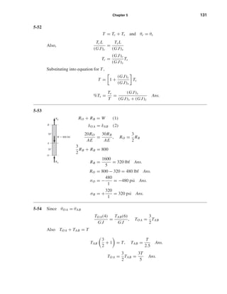
5-55
F1 = F2 ⇒
T1
r1
=
T2
r2
⇒
T1
1.25
=
T2
3
T2 =
3
1.25
T1
∴ θ1 +
3
1.25
θ2 =
4π
180
rad
T1(48)
(π/32)(7/8)4(11.5)(106)
+
3
1.25
(3/1.25)T1(48)
(π/32)(1.25)4(11.5)(106)
=
4π
180
T1 = 403.9 lbf · in
T2 =
3
1.25
T1 = 969.4 lbf · in
τ1 =
16T1
πd3
=
16(403.9)
π(7/8)3
= 3071 psi Ans.
τ2 =
16(969.4)
π(1.25)3
= 2528 psi Ans.
5-56
(1) Arbitrarily, choose RC as redundant reaction
(2) Fx = 0, 10(103
) − 5(103
) − RO − RC = 0
RO + RC = 5(103
) lbf
(3) δC =
[10(103
) − 5(103
) − RC]20
AE
−
[5(103
) + RC]
AE
(10) −
RC(15)
AE
= 0
−45RC + 5(104
) = 0 ⇒ RC = 1111 lbf Ans.
RO = 5000 − 1111 = 3889 lbf Ans.
5-57
(1) Choose RB as redundant reaction
(2) RB + RC = wl (a) RB(l − a) −
wl2
2
+ MC = 0 (b)
RB
A
x
w
RC
CB
MC
a
l
10 kip 5 kip
FA FB RCRO x
shi20396_ch05.qxd 8/18/03 10:59 AM Page 132](https://image.slidesharecdn.com/captulo05-deflexoerigidez-140621145643-phpapp01/85/Capitulo-05-deflexao-e-rigidez-27-320.jpg)
![Chapter 5 133
(3) yB =
RB(l − a)3
3E I
+
w(l − a)2
24E I
[4l(l − a) − (l − a)2
− 6l2
] = 0
RB =
w
8(l − a)
[6l2
− 4l(l − a) + (l − a)2
]
=
w
8(l − a)
(3l2
+ 2al + a2
) Ans.
Substituting,
Eq. (a) RC = wl − RB =
w
8(l − a)
(5l2
− 10al − a2
) Ans.
Eq. (b) MC =
wl2
2
− RB(l − a) =
w
8
(l2
− 2al − a2
) Ans.
5-58
M = −
wx2
2
+ RB x − a 1
,
∂M
∂ RB
= x − a 1
∂U
∂ RB
=
1
E I
l
0
M
∂M
∂ RB
dx
=
1
E I
a
0
−wx2
2
(0) dx +
1
E I
l
a
−wx2
2
+ RB(x − a) (x − a) dx = 0
−
w
2
1
4
(l4
− a4
) −
a
3
(l3
− a3
) +
RB
3
(l − a)3
− (a − a)3
= 0
RB =
w
(l − a)3
[3(L4
− a4
) − 4a(l3
− a3
)] =
w
8(l − a)
(3l2
+ 2al + a2
) Ans.
RC = wl − RB =
w
8(l − a)
(5l2
− 10al − a2
) Ans.
MC =
wl2
2
− RB(l − a) =
w
8
(l2
− 2al − a2
) Ans.
5-59
A =
π
4
(0.0122
) = 1.131(10−4
) m2
(1) RA + FBE + FDF = 20 kN (a)
MA = 3FDF − 2(20) + FBE = 0
FBE + 3FDF = 40 kN (b)
FBE FDF
D
C
20 kN
500500 500
B
A
RA
RB
A
a B C
RC
MC
x
w
shi20396_ch05.qxd 8/18/03 10:59 AM Page 133](https://image.slidesharecdn.com/captulo05-deflexoerigidez-140621145643-phpapp01/85/Capitulo-05-deflexao-e-rigidez-28-320.jpg)
![Chapter 5 135
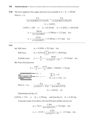
5-60
E I = 30(106
)(0.050) = 1.5(106
) lbf · in2
(1) RC + FBE − FFD = 500 (a)
3RC + 6FBE = 9(500) = 4500 (b)
(2) M = −500x + FBE x − 3 1
+ RC x − 6 1
E I
dy
dx
= −250x2
+
FBE
2
x − 3 2
+
RC
2
x − 6 2
+ C1
E I y = −
250
3
x3
+
FBE
6
x − 3 3
+
RC
6
x − 6 3
+ C1x + C2
yB =
Fl
AE BE
= −
FBE(2)
(π/4)(5/16)2(30)(106)
= −8.692(10−7
)FBE
Substituting and evaluating at x = 3 in
E I yB = 1.5(106
)[−8.692(10−7
)FBE] = −
250
3
(33
) + 3C1 + C2
1.3038FBE + 3C1 + C2 = 2250 (c)
Since y = 0 at x = 6 in
E I y|=0 = −
250
3
(63
) +
FBE
6
(6 − 3)3
+ 6C1 + C2
4.5FBE + 6C1 + C2 = 1.8(104
) (d)
yD =
Fl
AE DF
=
FDF(2.5)
(π/4)(5/16)2(30)(106)
= 1.0865(10−6
)FDF
Substituting and evaluating at x = 9 in
E I yD = 1.5(106
)[1.0865(10−6
)FDF] = −
250
3
(93
) +
FBE
6
(9 − 3)3
+
RC
6
(9 − 6)3
+ 9C1 + C2
4.5RC + 36FBE − 1.6297FDF + 9C1 + C2 = 6.075(104
) (e)
1 1 −1 0 0
3 6 0 0 0
0 1.3038 0 3 1
0 4.5 0 6 1
4.5 36 −1.6297 9 1
RC
FBE
FDF
C1
C2
=
500
4500
2250
1.8(104
)
6.075(104
)
RC = −590.4 lbf, FBE = 1045.2 lbf, FDF = −45.2 lbf
C1 = 4136.4 lbf · in2
, C2 = −11 522 lbf · in3
FBE
A B
C D
FFDRC
3"3"
500 lbf
y
3"
x
shi20396_ch05.qxd 8/18/03 10:59 AM Page 135](https://image.slidesharecdn.com/captulo05-deflexoerigidez-140621145643-phpapp01/85/Capitulo-05-deflexao-e-rigidez-30-320.jpg)
![Chapter 5 137
Since I = bh3
/12 = 4(6)3
/12 = 72 mm4
and R = 81/2 = 40.5 mm, we have
δ =
3π(40.5)3
F
131(72)
= 66.4F mm Ans.
where F is in kN.
5-63
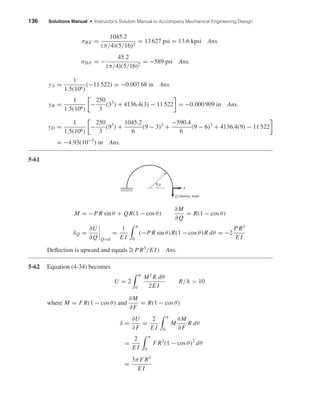
M = −Px,
∂M
∂ P
= −x 0 ≤ x ≤ l
M = Pl + P R(1 − cos θ),
∂M
∂ P
= l + R(1 − cos θ) 0 ≤ θ ≤ l
δP =
1
E I
l
0
−Px(−x) dx +
π/2
0
P[l + R(1 − cos θ)]2
R dθ
=
P
12E I
{4l3
+ 3R[2πl2
+ 4(π − 2)l R + (3π − 8)R2
]} Ans.
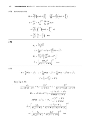
5-64 A: Dummy load Q is applied at A. Bending in AB due only to Q which is zero.
M = P R sin θ + QR(1 + sin θ),
∂M
∂Q
= R(1 + sin θ) 0 ≤ θ ≤
π
2
(δA)V =
∂U
∂Q Q=0
=
1
E I
π/2
0
(P R sin θ)[R(1 + sin θ)]R dθ
=
P R3
E I
−cos θ +
θ
2
−
sin 2θ
4
π/2
0
=
P R3
E I
1 +
π
4
=
π + 4
4
P R3
E I
Ans.
P
Q
B
A
C
P
x
l
R
shi20396_ch05.qxd 8/18/03 10:59 AM Page 137](https://image.slidesharecdn.com/captulo05-deflexoerigidez-140621145643-phpapp01/85/Capitulo-05-deflexao-e-rigidez-32-320.jpg)
![138 Solutions Manual • Instructor’s Solution Manual to Accompany Mechanical Engineering Design
B: M = P R sin θ,
∂M
∂ P
= R sin θ
(δB)V =
∂U
∂ P
=
1
E I
π/2
0
(P R sin θ)(R sin θ)R dθ
=
π
4
P R3
E I
Ans.
5-65
M = P R sin θ,
∂M
∂ P
= R sin θ 0 < θ <
π
2
T = P R(1 − cos θ),
∂T
∂ P
= R(1 − cos θ)
(δA)y = −
∂U
∂ P
= −
1
E I
π/2
0
P(R sin θ)2
R dθ +
1
G J
π/2
0
P[R(1 − cos θ)]2
R dθ
Integrating and substituting J = 2I and G = E/[2(1 + ν)]
(δA)y = −
P R3
E I
π
4
+ (1 + ν)
3π
4
− 2 = −[4π − 8 + (3π − 8)ν]
P R3
4E I
= −[4π − 8 + (3π − 8)(0.29)]
(200)(100)3
4(200)(103)(π/64)(5)4
= −40.6 mm
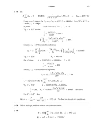
5-66 Consider the horizontal reaction, to be applied at B, subject to the constraint (δB)H = 0.
(a) (δB)H =
∂U
∂ H
= 0
Due to symmetry, consider half of the structure. P does not deflect horizontally.
P
A
B H
R
P
2
A
R
z
x
y
M
T
200 N
200 N
shi20396_ch05.qxd 8/18/03 10:59 AM Page 138](https://image.slidesharecdn.com/captulo05-deflexoerigidez-140621145643-phpapp01/85/Capitulo-05-deflexao-e-rigidez-33-320.jpg)
![Chapter 5 139
M =
P R
2
(1 − cos θ) − H R sin θ,
∂M
∂ H
= −R sin θ, 0 < θ <
π
2
∂U
∂ H
=
1
E I
π/2
0
P R
2
(1 − cos θ) − H R sin θ (−R sin θ)R dθ = 0
−
P
2
+
P
4
+ H
π
4
= 0 ⇒ H =
P
π
Ans.
Reaction at A is the same where H goes to the left
(b) For 0 < θ <
π
2
, M =
P R
2
(1 − cos θ) −
P R
π
sin θ
M =
P R
2π
[π(1 − cos θ) − 2 sin θ] Ans.
Due to symmetry, the solution for the left side is identical.
(c)
∂M
∂ P
=
R
2π
[π(1 − cos θ) − 2 sin θ]
δP =
∂U
∂ P
=
2
E I
π/2
0
P R2
4π2
[π(1 − cos θ) − 2 sin θ]2
R dθ
=
P R3
2π2 E I
π/2
0
(π2
+ π2
cos2
θ + 4 sin2
θ − 2π2
cos θ
− 4π sin θ + 4π sin θ cos θ) dθ
=
P R3
2π2 E I
π2 π
2
+ π2 π
4
+ 4
π
4
− 2π2
− 4π + 2π
=
(3π2
− 8π − 4)
8π
P R3
E I
Ans.
5-67 Must use Eq. (5-34)
A = 80(60) − 40(60) = 2400 mm2
R =
(25 + 40)(80)(60) − (25 + 20 + 30)(40)(60)
2400
= 55 mm
Section is equivalent to the “T” section of Table 4-5
rn =
60(20) + 20(60)
60 ln[(25 + 20)/25] + 20 ln[(80 + 25)/(25 + 20)]
= 45.9654 mm
e = R − rn = 9.035 mm
Iz =
1
12
(60)(203
) + 60(20)(30 − 10)2
+ 2
1
12
(10)(603
) + 10(60)(50 − 30)2
= 1.36(106
) mm4
y
z
30 mm
50 mm
Straight section
shi20396_ch05.qxd 8/18/03 10:59 AM Page 139](https://image.slidesharecdn.com/captulo05-deflexoerigidez-140621145643-phpapp01/85/Capitulo-05-deflexao-e-rigidez-34-320.jpg)
![140 Solutions Manual • Instructor’s Solution Manual to Accompany Mechanical Engineering Design
For 0 ≤ x ≤ 100 mm
M = −Fx,
∂M
∂F
= −x; V = F,
∂V
∂F
= 1
For θ ≤ π/2
Fr = F cos θ,
∂Fr
∂F
= cos θ; Fθ = F sin θ,
∂Fθ
∂F
= sin θ
M = F(100 + 55 sin θ),
∂M
∂F
= (100 + 55 sin θ)
Use Eq. (5-34), integrate from 0 to π/2, double the results and add straight part
δ =
2
E
1
I
100
0
Fx2
dx +
100
0
(1)F(1) dx
2400(G/E)
+
π/2
0
F
(100 + 55 sin θ)2
2400(9.035)
dθ
+
π/2
0
F sin2
θ(55)
2400
dθ −
π/2
0
F(100 + 55 sin θ)
2400
sin θdθ
−
π/2
0
F sin θ(100 + 55 sin θ)
2400
dθ +
π/2
0
(1)F cos2
θ(55)
2400(G/E)
dθ
Substitute
I = 1.36(103
) mm2
, F = 30(103
) N, E = 207(103
) N/mm2
, G = 79(103
) N/mm2
δ =
2
207(103)
30(103
)
1003
3(1.36)(106)
+
207
79
100
2400
+
2.908(104
)
2400(9.035)
+
55
2400
π
4
−
2
2400
(143.197) +
207
79
55
2400
π
4
= 0.476 mm Ans.
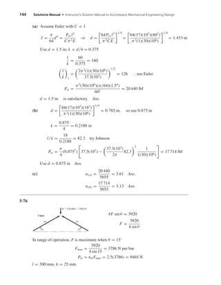
5-68
M = F R sin θ − QR(1 − cos θ),
∂M
∂Q
= −R(1 − cos θ)
Fθ = Q cos θ + F sin θ,
∂Fθ
∂Q
= cos θ
∂
∂Q
(M Fθ ) = [F R sin θ − QR(1 − cos θ)] cos θ
+ [−R(1 − cos θ)][Q cos θ + F sin θ]
Fr = F cos θ − Q sin θ,
∂Fr
∂Q
= −sin θ
Q
F
M
R
Fr
F
F
FFr
M
100 mm
x
shi20396_ch05.qxd 8/18/03 10:59 AM Page 140](https://image.slidesharecdn.com/captulo05-deflexoerigidez-140621145643-phpapp01/85/Capitulo-05-deflexao-e-rigidez-35-320.jpg)
![Chapter 5 141
From Eq. (5-34)
δ =
∂U
∂Q Q=0
=
1
AeE
π
0
(F R sin θ)[−R(1 − cos θ)] dθ +
R
AE
π
0
F sin θ cos θdθ
−
1
AE
π
0
[F R sin θ cos θ − F R sin θ(1 − cos θ)] dθ
+
C R
AG
π
0
−F cos θ sin θdθ
= −
2F R2
AeE
+ 0 +
2F R
AE
+ 0 = −
R
e
− 1
2F R
AE
Ans.
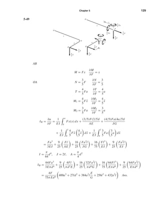
5-69 The cross section at A does not rotate, thus for a single quadrant we have
∂U
∂MA
= 0
The bending moment at an angle θ to the x axis is
M = MA −
F
2
(R − x) = MA −
F R
2
(1 − cos θ) (1)
because x = R cos θ. Next,
U =
M2
2E I
ds =
π/2
0
M2
2E I
R dθ
since ds = R dθ. Then
∂U
∂MA
=
R
E I
π/2
0
M
∂M
∂MA
dθ = 0
But ∂M/∂MA = 1. Therefore
π/2
0
M dθ =
π/2
0
MA −
F R
2
(1 − cos θ) dθ = 0
Since this term is zero, we have
MA =
F R
2
1 −
2
π
Substituting into Eq. (1)
M =
F R
2
cos θ −
2
π
The maximum occurs at B where θ = π/2. It is
MB = −
F R
π
Ans.
shi20396_ch05.qxd 8/18/03 10:59 AM Page 141](https://image.slidesharecdn.com/captulo05-deflexoerigidez-140621145643-phpapp01/85/Capitulo-05-deflexao-e-rigidez-36-320.jpg)
![146 Solutions Manual • Instructor’s Solution Manual to Accompany Mechanical Engineering Design
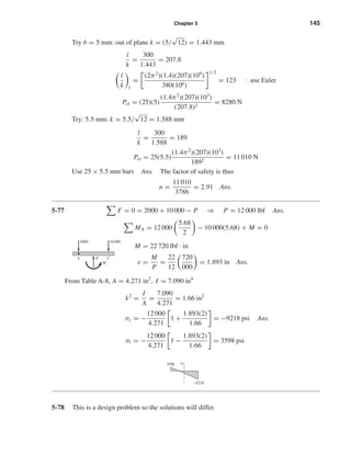
5-79 For free fall with y ≤ h
Fy − m ¨y = 0
mg − m ¨y = 0, so ¨y = g
Using y = a + bt + ct2
, we have at t = 0, y = 0, and ˙y = 0, and so a = 0, b = 0, and
c = g/2. Thus
y =
1
2
gt2
and ˙y = gt for y ≤ h
At impact, y = h, t = (2h/g)1/2
, and v0 = (2gh)1/2
After contact, the differential equatioin (D.E.) is
mg − k(y − h) − m ¨y = 0 for y > h
Now let x = y − h; then ˙x = ˙y and ¨x = ¨y. So the D.E. is ¨x + (k/m)x = g with solution
ω = (k/m)1/2
and
x = A cos ωt + B sin ωt +
mg
k
At contact, t = 0, x = 0, and ˙x = v0 . Evaluating A and B then yields
x = −
mg
k
cos ωt +
v0
ω
sin ωt +
mg
k
or
y = −
W
k
cos ωt +
v0
ω
sin ωt +
W
k
+ h
and
˙y =
Wω
k
sin ωt + v0 cos ωt
To find ymax set ˙y = 0. Solving gives
tan ωt = −
v0k
Wω
or (ωt )* = tan−1
−
v0k
Wω
The first value of (ωt )* is a minimum and negative. So add π radians to it to find the
maximum.
Numerical example: h = 1 in, W = 30 lbf, k = 100 lbf/in. Then
ω = (k/m)1/2
= [100(386)/30]1/2
= 35.87 rad/s
W/k = 30/100 = 0.3
v0 = (2gh)1/2
= [2(386)(1)]1/2
= 27.78 in/s
Then
y = −0.3 cos 35.87t +
27.78
35.87
sin 35.87t + 0.3 + 1
mg
y
k(y Ϫ h)
mg
y
shi20396_ch05.qxd 8/18/03 10:59 AM Page 146](https://image.slidesharecdn.com/captulo05-deflexoerigidez-140621145643-phpapp01/85/Capitulo-05-deflexao-e-rigidez-41-320.jpg)
![148 Solutions Manual • Instructor’s Solution Manual to Accompany Mechanical Engineering Design
Then
B =
v2
ω
=
W1(2gh)1/2
(W1 + W2)[kg/(W1 + W2)]1/2
We now have
y = −
W1
k
cos ωt + W1
2h
k(W1 + W2)
1/2
sin ωt +
W1
k
Transforming gives
y =
W1
k
2hk
W1 + W2
+ 1
1/2
cos(ωt − φ) +
W1
k
where φ is a phase angle. The maximum deflection of W2 and the maximum spring force
are thus
ymax =
W1
k
2hk
W1 + W2
+ 1
1/2
+
W1
k
Ans.
Fmax = kymax + W2 = W1
2hk
W1 + W2
+ 1
1/2
+ W1 + W2 Ans.
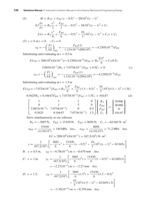
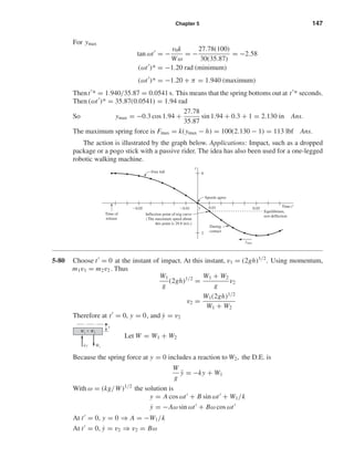
5-81 Assume x > y to get a free-body diagram.
Then
W
g
¨y = k1(x − y) − k2y
A particular solution for x = a is
y =
k1a
k1 + k2
Then the complementary plus the particular solution is
y = A cos ωt + B sin ωt +
k1a
k1 + k2
where ω =
(k1 + k2)g
W
1/2
At t = 0, y = 0, and ˙y = 0. Therefore B = 0 and
A = −
k1a
k1 + k2
Substituting,
y =
k1a
k1 + k2
(1 − cos ωt)
Since y is maximum when the cosine is −1
ymax =
2k1a
k1 + k2
Ans.
k1(x Ϫ y) k2y
W
y
x
shi20396_ch05.qxd 8/18/03 10:59 AM Page 148](https://image.slidesharecdn.com/captulo05-deflexoerigidez-140621145643-phpapp01/85/Capitulo-05-deflexao-e-rigidez-43-320.jpg)

This document contains solutions to problems from Chapter 5 of an engineering textbook. Problem 5-3 calculates the torque and allowable twist in a torsion bar made of two springs in parallel. Problem 5-12 calculates the maximum deflection and stress in a beam loaded by two point loads. Problem 5-19 involves selecting the appropriate cross-sectional dimensions to achieve a required stiffness for a beam of given length.