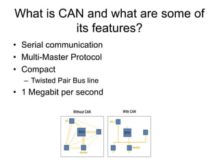
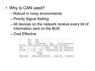
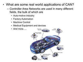
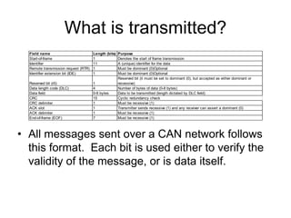
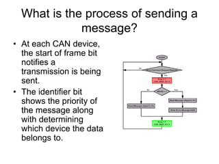
Introduction to CAN
What is CAN and what are some of
its features?
• Serial communication
• Multi-Master Protocol
• Compact
– Twisted Pair Bus line
• 1 Megabit per second
• Why is CAN used?
– Robust in noisy environments
– Priority Signal Setting
– All devices on the network receive every bit of
information sent on the BUS
– Cost Effective
• What are some real world applications of CAN?
– Controller Area Networks are used in many different
fields, the bulk of which are
• Auto-motive industry
• Factory Automation
• Machine Control
• Medical Equipment and devices
• And more….
What is transmitted?
• All messages sent over a CAN network follows
this format. Each bit is used either to verify the
validity of the message, or is data itself.
Field name Length (bits) Purpose
Start-of-frame 1 Denotes the start of frame transmission
Identifier 11 A (unique) identifier for the data
Remote transmission request (RTR) 1 Must be dominant (0)Optional
Identifier extension bit (IDE) 1 Must be dominant (0)Optional
Reserved bit (r0) 1
Reserved bit (it must be set to dominant (0), but accepted as either dominant or
recessive)
Data length code (DLC) 4 Number of bytes of data (0-8 bytes)
Data field 0-8 bytes Data to be transmitted (length dictated by DLC field)
CRC 15 Cyclic redundancy check
CRC delimiter 1 Must be recessive (1)
ACK slot 1 Transmitter sends recessive (1) and any receiver can assert a dominant (0)
ACK delimiter 1 Must be recessive (1)
End-of-frame (EOF) 7 Must be recessive (1)
What is the process of sending a
message?
• At each CAN device,
the start of frame bit
notifies a
transmission is being
sent.
• The identifier bit
shows the priority of
the message along
with determining
which device the data
belongs to.
CAN Message Transmission
Basic message frame format
Field name
Length
(bits) Purpose
Start-of-frame 1 Denotes the start of frame transmission
Identifier 11 A (unique) identifier for the data
Remote transmission request (RTR) 1 Must be dominant (0)
Identifier extension bit (IDE) 1 Must be dominant (0)
Reserved bit (r0) 1
Reserved bit (it must be set to dominant (0), but accepted
as either dominant or recessive)
Data length code (DLC) 4 Number of bytes of data (0-8 bytes)
Data field 0-8 bytes Data to be transmitted (length dictated by DLC field)
CRC 15 Cyclic redundancy check
CRC delimiter 1 Must be recessive (1)
ACK slot 1
Transmitter sends recessive (1) and any receiver can
assert a dominant (0)
ACK delimiter 1 Must be recessive (1)
End-of-frame (EOF) 7 Must be recessive (1)
Arbitration Field
Message Objects
• 32 message objects
• Configured to transmit or receive or both
• Configured using the Message Object Interface
Registers
• Each identifier is stored in a Message object.
• Message number is the receive/transmit priority for the
Message Objects
– Message Object 1 has the highest priority, while Message Object
32 has the lowest priority
Message Object Interface register
• ID28-0 Message Identifier
– ID28 - ID0 29-bit Identifier (“Extended Frame”).
– ID28 - ID18 11-bit Identifier (“Standard Frame”).
• Dir Message Direction
– one Direction = transmit
– zero Direction = receive
• Data 0 1st data byte of a CAN Data Frame
• Data 1 2nd data byte of a CAN Data Frame
Error Field
• Enable test mode to use the modes below
• Loop Back Mode
• Silent Mode
• Basic Mode
Status Register
– Transmit successfully
– Receive successfully
– Stuff Error -Form Error
– AckError -Bit1Error
– Bit0Error -CRCError
Debugging
• Oscilloscope
– Useful in Lab 1
• read the message frame and error bits
• calculate the frequency of a message frame
Components for Lab 1
• Slide Switch
• 74F365 Hex Buffer
• Bi color LED

CAN_lecture.pdf

  • 1.
  • 2.
    What is CANand what are some of its features? • Serial communication • Multi-Master Protocol • Compact – Twisted Pair Bus line • 1 Megabit per second
  • 3.
    • Why isCAN used? – Robust in noisy environments – Priority Signal Setting – All devices on the network receive every bit of information sent on the BUS – Cost Effective
  • 4.
    • What aresome real world applications of CAN? – Controller Area Networks are used in many different fields, the bulk of which are • Auto-motive industry • Factory Automation • Machine Control • Medical Equipment and devices • And more….
  • 5.
    What is transmitted? •All messages sent over a CAN network follows this format. Each bit is used either to verify the validity of the message, or is data itself. Field name Length (bits) Purpose Start-of-frame 1 Denotes the start of frame transmission Identifier 11 A (unique) identifier for the data Remote transmission request (RTR) 1 Must be dominant (0)Optional Identifier extension bit (IDE) 1 Must be dominant (0)Optional Reserved bit (r0) 1 Reserved bit (it must be set to dominant (0), but accepted as either dominant or recessive) Data length code (DLC) 4 Number of bytes of data (0-8 bytes) Data field 0-8 bytes Data to be transmitted (length dictated by DLC field) CRC 15 Cyclic redundancy check CRC delimiter 1 Must be recessive (1) ACK slot 1 Transmitter sends recessive (1) and any receiver can assert a dominant (0) ACK delimiter 1 Must be recessive (1) End-of-frame (EOF) 7 Must be recessive (1)
  • 6.
    What is theprocess of sending a message? • At each CAN device, the start of frame bit notifies a transmission is being sent. • The identifier bit shows the priority of the message along with determining which device the data belongs to.
  • 7.
  • 8.
    Basic message frameformat Field name Length (bits) Purpose Start-of-frame 1 Denotes the start of frame transmission Identifier 11 A (unique) identifier for the data Remote transmission request (RTR) 1 Must be dominant (0) Identifier extension bit (IDE) 1 Must be dominant (0) Reserved bit (r0) 1 Reserved bit (it must be set to dominant (0), but accepted as either dominant or recessive) Data length code (DLC) 4 Number of bytes of data (0-8 bytes) Data field 0-8 bytes Data to be transmitted (length dictated by DLC field) CRC 15 Cyclic redundancy check CRC delimiter 1 Must be recessive (1) ACK slot 1 Transmitter sends recessive (1) and any receiver can assert a dominant (0) ACK delimiter 1 Must be recessive (1) End-of-frame (EOF) 7 Must be recessive (1)
  • 9.
  • 10.
    Message Objects • 32message objects • Configured to transmit or receive or both • Configured using the Message Object Interface Registers • Each identifier is stored in a Message object. • Message number is the receive/transmit priority for the Message Objects – Message Object 1 has the highest priority, while Message Object 32 has the lowest priority
  • 11.
    Message Object Interfaceregister • ID28-0 Message Identifier – ID28 - ID0 29-bit Identifier (“Extended Frame”). – ID28 - ID18 11-bit Identifier (“Standard Frame”). • Dir Message Direction – one Direction = transmit – zero Direction = receive • Data 0 1st data byte of a CAN Data Frame • Data 1 2nd data byte of a CAN Data Frame
  • 12.
  • 13.
    • Enable testmode to use the modes below • Loop Back Mode • Silent Mode • Basic Mode
  • 14.
    Status Register – Transmitsuccessfully – Receive successfully – Stuff Error -Form Error – AckError -Bit1Error – Bit0Error -CRCError
  • 15.
    Debugging • Oscilloscope – Usefulin Lab 1 • read the message frame and error bits • calculate the frequency of a message frame
  • 16.
    Components for Lab1 • Slide Switch • 74F365 Hex Buffer • Bi color LED