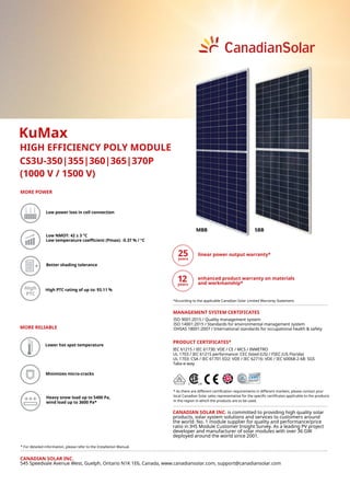
The selection of suitable values for the insulation levels of the various components in any electrical system and their arrangement in a rational manner is called insulation coordination.
The insulation level of an apparatus is defined as that combination of voltage values (both power frequency and impulse) which characterize it insulation with regard to its capability of withstanding the dielectric stress
The 7SD610 relay is a differential protection relay suitable for all types of applications and incorporating all those functions required for differential protection of lines, cables and transformers. Transformers and compensation coils within the differential protection zone are protected by means of integrated functions, which were previously to be found only in transformer differential protection. It is also well-suited for complex applications such as series and parallel compensation of lines and cables.
It is that branch of welding in which Electric current is used to produce the large heat required for joining together into firm two pieces of metals.
Electrical welding process fall into two main categories
RESISTANCE WELDING.
ARC WELDING.
The term Load Despatch Centre (LDC) was first time referred in the Electricity Supply Act 1948 vide
amendment dated 15th October 1991. The subsequent amendment in August 1998 designated the LDC
as an apex body and enumerated the roles, responsibilities and powers of LDC for ensuring smooth
and integrated grid operation. The Electricity Act 2003 further articulated these provisions and
defined real-time operations. The National Load Despatch Centre (NLDC) Rules, March 2005 by
Govt. of India enumerated the functions of NLDC in detail.
The Electricity Act 2003 as well as the MoP resolution of 2005, mandated that the Central / State
Transmission Utilities shall operate the respective Load Despatch Centres until a Government
company or any authority or corporation is notified by the Central/State Government. The amendment
of the Electricity Supply Act 1948 and subsequently the Electricity Act 2003 provided for levy and
collection of fee and charges as may be specified by the appropriate Electricity Regulatory
Commission.
Back ground
The Electricity Act 2003 introduced competition in the power sector by delicensing generation,
introducing open access in transmission and emphasizing that Load Despatch Centres must be
transparent, neutral and non-discriminate. Under the changed paradigm, the issues related to the
institutional arrangement, functional autonomy, revenue streams as well as certification and incentives
for human resources were re-examined by the committees / Task Forces constituted by the MoP, GoI.
Pursuant to the recommendations of the Forum of Regulators’ report on ‘Open Access-Theory and
Practice’, the Central Electricity Regulatory Commission notified the Regulations on fees and charges
for Regional Load Despatch Centre in September 2009. Chairperson CERC and FOR, urged the
SERCs to initiate steps to frame regulations for State LDCs based on the principles laid down in the
regulations framed by CERC for the RLDC.
The Republic of the Union of Myanmar Ministry of Electricity and Energy Hydro...MYO AUNG Myanmar
THE REPUBLIC OF THE UNION OF MYANMAR
MINISTRY OF ELECTRICITY AND ENERGY
HYDROPOWER DEVELOPMENT PLANS
http://www.ifc.org/wps/wcm/connect/e46682d2-cc3a-4d3c-9bc5-02496244c6b9/IFC's+General+Forum++(11+8+2016)UAKK.pdf?MOD=AJPERES
Hydropower Potential in Myanmar
Reforming the Philippine Electric Power Industry Reform Act (EPIRA)Elvin Uy
Analysis of RA 9136, the Electric Power Industry Reform Act, for my Policy Analysis I course in Carnegie Mellon in 2010. Full paper can be viewed here: http://scr.bi/HNHTHU
Our ATEX -products
ATEX APPROVED LOW GAIN BASE STATION ANTENNA AV1312-1A-EXnA-131FN2
ATEX APPROVED LOW GAIN BASE STATION ANTENNA AV1312-2-EXnA-160FN2
ATEX APPROVED LOW GAIN BASE STATION ANTENNA AV1314-H-EXnA-440FN2
ATEX APPROVED LOW GAIN BASE STATION ANTENNA AV1314-R-H-EXnA-440FN2
ATEX APPROVED LOW GAIN BASE STATION ANTENNA AV1314-T-H-EXnA-440FN2
ATEX APPROVED MEDIUM GAIN BASE STATION ANTENNA AV1430-EXnA-131FN2
ATEX APPROVED MEDIUM GAIN BASE STATION ANTENNA AV1431-EXnA-160FN2
ATEX APPROVED YAGI ANTENNA AV1468-EXnA-…FN2
ATEX APPROVED MEDIUM GAIN BASE STATION ANTENNA AV1915-H-EXnA-440FN2
ATEX APPROVED MEDIUM GAIN BASE STATION ANTENNA AV1916-EXnA-915FN2
ATEX APPROVED POWER DIVIDER TR2401-EXnA-160FN1
ATEX APPROVED POWER DIVIDER TR1:2-150-470-EXnA-FN1 (TR2481-EXnA-310FN1)
ATEX APPROVED POWER DIVIDER TR4501-EXnA-405FN1
ATEX APPROVED POWER DIVIDER TR1:4-150-470-EXnA-FN1 (TR4481-EXnA-310FN1)
ATEX APPROVED POWER DIVIDER TR2501-EXnA-405FN1
AC LINE DESIGN
ELECTRICAL CHARACTERISTICS
MECHANICAL CHARACTERISTICS
THERMAL RATING
PLANNERS REQUIREMENTS
OBJECTIVE INDICATOR
DC LINE DESIGN
ELECTRICAL CHARACTERISTICS
OBJECTIVE INDICATOR
COST OF LINES
EXAMPLES OF OPTIMISATION
72 Cell Modules and 60 cell modules (multi-crystalline)Emmvee India
72 Mono Crystalline Cell Modules:
The Monocrystalline modules can be used where discrete but powerful performance is required. The modules are designed in accordance with the specific need for a particular solar product out there. Some of its salient features are listed below:
1. Effective tackling of weather conditions such as a strong hail with resistance to speed up to 83 km/h so that your device is not damaged.
2. Excellent operating temperature range.
3. Optimum yield even in fluctuating voltages and current.
4. A 3.2 mm high transmission tempered glass that takes the overall performance of this module to a new high.
5. The material used in the construction can sustain adverse conditions like excessive sun exposure, heavy rainfall etc.
6. Class II protection so that the user gets at least two layers of insulation from unintended damage to the equipment.
60 Multi-crystalline Cell Modules:
The 60 cell monocrystalline modules are well suited for those solar products that require optimum power efficiency but with less amount of cells. The Monocrystalline module is specifically designed to match the performance needs of a certain solar application.
Some of its features can be seen as follows:
1. The low weight of just 18 kgs makes it an ergonomic module to use.
2. A 3.2 mm high transmission tempered glass that takes the overall performance of this module to a new high.
3. Effective tackling of weather conditions such as a strong hail with resistance to speed up to 83 km/h so that your device is not damaged.
4. Excellent operating temperature range.
Class II protection so that the user gets at least two layers of insulation from unintended damage to the equipment
60 Monocrystalline Cell Modules and 72 Mono Crystalline Cell Modules: Emmvee India
60 Monocrystalline Cell Modules:
The 60 cell monocrystalline modules are well suited for those solar products that require optimum power efficiency but with less amount of cells. The Monocrystalline module is specifically designed to match the performance needs of a certain solar application.
Some of its features can be seen as follows:
1. The low weight of just 18 kgs makes it an ergonomic module to use.
2. A 3.2 mm high transmission tempered glass that takes the overall performance of this module to a new high.
3. Effective tackling of weather conditions such as a strong hail with resistance to speed up to 83 km/h so that your device is not damaged.
4. Excellent operating temperature range.
5. Class II protection so that the user gets at least two layers of insulation from unintended damage to the equipment
72 Mono Crystalline Cell Modules:
The Monocrystalline modules can be used where discrete but powerful performance is required. The modules are designed in accordance with the specific need for a particular solar product out there. Some of its salient features are listed below:
1. Effective tackling of weather conditions such as a strong hail with resistance to speed up to 83 km/h so that your device is not damaged.
2. Excellent operating temperature range.
3. Optimum yield even in fluctuating voltages and current.
4. A 3.2 mm high transmission tempered glass that takes the overall performance of this module to a new high.
5. The material used in the construction can sustain adverse conditions like excessive sun exposure, heavy rainfall etc.
6. Class II protection so that the user gets at least two layers of insulation from unintended damage to the equipment.
Automobile Management System Project Report.pdfKamal Acharya
The proposed project is developed to manage the automobile in the automobile dealer company. The main module in this project is login, automobile management, customer management, sales, complaints and reports. The first module is the login. The automobile showroom owner should login to the project for usage. The username and password are verified and if it is correct, next form opens. If the username and password are not correct, it shows the error message.
When a customer search for a automobile, if the automobile is available, they will be taken to a page that shows the details of the automobile including automobile name, automobile ID, quantity, price etc. “Automobile Management System” is useful for maintaining automobiles, customers effectively and hence helps for establishing good relation between customer and automobile organization. It contains various customized modules for effectively maintaining automobiles and stock information accurately and safely.
When the automobile is sold to the customer, stock will be reduced automatically. When a new purchase is made, stock will be increased automatically. While selecting automobiles for sale, the proposed software will automatically check for total number of available stock of that particular item, if the total stock of that particular item is less than 5, software will notify the user to purchase the particular item.
Also when the user tries to sale items which are not in stock, the system will prompt the user that the stock is not enough. Customers of this system can search for a automobile; can purchase a automobile easily by selecting fast. On the other hand the stock of automobiles can be maintained perfectly by the automobile shop manager overcoming the drawbacks of existing system.
CFD Simulation of By-pass Flow in a HRSG module by R&R Consult.pptxR&R Consult
CFD analysis is incredibly effective at solving mysteries and improving the performance of complex systems!
Here's a great example: At a large natural gas-fired power plant, where they use waste heat to generate steam and energy, they were puzzled that their boiler wasn't producing as much steam as expected.
R&R and Tetra Engineering Group Inc. were asked to solve the issue with reduced steam production.
An inspection had shown that a significant amount of hot flue gas was bypassing the boiler tubes, where the heat was supposed to be transferred.
R&R Consult conducted a CFD analysis, which revealed that 6.3% of the flue gas was bypassing the boiler tubes without transferring heat. The analysis also showed that the flue gas was instead being directed along the sides of the boiler and between the modules that were supposed to capture the heat. This was the cause of the reduced performance.
Based on our results, Tetra Engineering installed covering plates to reduce the bypass flow. This improved the boiler's performance and increased electricity production.
It is always satisfying when we can help solve complex challenges like this. Do your systems also need a check-up or optimization? Give us a call!
Work done in cooperation with James Malloy and David Moelling from Tetra Engineering.
More examples of our work https://www.r-r-consult.dk/en/cases-en/
Welcome to WIPAC Monthly the magazine brought to you by the LinkedIn Group Water Industry Process Automation & Control.
In this month's edition, along with this month's industry news to celebrate the 13 years since the group was created we have articles including
A case study of the used of Advanced Process Control at the Wastewater Treatment works at Lleida in Spain
A look back on an article on smart wastewater networks in order to see how the industry has measured up in the interim around the adoption of Digital Transformation in the Water Industry.
TECHNICAL TRAINING MANUAL GENERAL FAMILIARIZATION COURSEDuvanRamosGarzon1
AIRCRAFT GENERAL
The Single Aisle is the most advanced family aircraft in service today, with fly-by-wire flight controls.
The A318, A319, A320 and A321 are twin-engine subsonic medium range aircraft.
The family offers a choice of engines
Canadian solar datasheet- ku-max_cs3u-p_high efficiency_v5.6_in
1. CS3U-350|355|360|365|370P
High High PTC rating of up to: 93.11 %
(1000 V / 1500 V)
KuMax
HIGH EFFICIENCY POLY MODULE
CANADIAN SOLAR INC.
545 Speedvale Avenue West, Guelph, Ontario N1K 1E6, Canada, www.canadiansolar.com, support@canadiansolar.com
Lower hot spot temperature
Low power loss in cell connection
Minimizes micro-cracks
Low NMOT: 42 ± 3 °C
Low temperature coefficient (Pmax): -0.37 % / °C
MORE POWER
Better shading tolerance
MORE RELIABLE
Heavy snow load up to 5400 Pa,
wind load up to 3600 Pa*
* For detailed information, please refer to the Installation Manual.
* As there are different certification requirements in different markets, please contact your
local Canadian Solar sales representative for the specific certificates applicable to the products
in the region in which the products are to be used.
linear power output warranty*
PRODUCT CERTIFICATES*
ISO 9001:2015 / Quality management system
ISO 14001:2015 / Standards for environmental management system
OHSAS 18001:2007 / International standards for occupational health & safety
MANAGEMENT SYSTEM CERTIFICATES
CANADIAN SOLAR INC. is committed to providing high quality solar
products, solar system solutions and services to customers around
the world. No. 1 module supplier for quality and performance/price
ratio in IHS Module Customer Insight Survey. As a leading PV project
developer and manufacturer of solar modules with over 36 GW
deployed around the world since 2001.
IEC 61215 / IEC 61730: VDE / CE / MCS / INMETRO
UL 1703 / IEC 61215 performance: CEC listed (US) / FSEC (US Florida)
UL 1703: CSA / IEC 61701 ED2: VDE / IEC 62716: VDE / IEC 60068-2-68: SGS
Take-e-way
5BBMBB
*According to the applicable Canadian Solar Limited Warranty Statement.
enhanced product warranty on materials
and workmanship*
2. PARTNER SECTION
TEMPERATURE CHARACTERISTICS
Specification Data
Temperature Coefficient (Pmax) -0.37 % / °C
Temperature Coefficient (Voc) -0.29 % / °C
Temperature Coefficient (Isc) 0.05 % / °C
Nominal Module Operating Temperature 42 ± 3°C
MECHANICAL DATA
Specification Data
Cell Type Poly-crystalline
Cell Arrangement 144 [2 X (12 X 6) ]
Dimensions
2000 X 992 X 35 mm
(78.7 X 39.1 X 1.38 in)
Weight 22.5 kg (49.6 lbs)
Front Cover 3.2 mm tempered glass
Frame
Anodized aluminium alloy,
crossbar enhanced
J-Box IP68, 3 bypass diodes
Cable 4 mm2
(IEC), 12 AWG (UL)
Cable Length
(Including Connector)
Portrait: 400 mm (15.7 in) (+) / 280 mm
(11.0 in) (-); landscape: 1250 mm (49.2 in);
leap-frog connection: 1670 mm (65.7 in)*
Connector T4 series
Per Pallet 30 pieces
Per Container (40' HQ) 660 pieces
* For detailed information, please contact your local Canadian Solar sales and technical
representatives.
CS3U-365P / I-V CURVES
CANADIAN SOLAR INC.
545 Speedvale Avenue West, Guelph, Ontario N1K 1E6, Canada, www.canadiansolar.com, support@canadiansolar.com
ENGINEERING DRAWING (mm)
Rear View Frame Cross Section A-A
* The specifications and key features contained in this datasheet may deviate slightly
from our actual products due to the on-going innovation and product enhancement.
Canadian Solar Inc. reserves the right to make necessary adjustments to the informa-
tion described herein at any time without further notice. Please be kindly advised that
PV modules should be handled and installed by qualified people who have professio-
nal skills and please carefully read the safety and installation instructions before using
our PV modules.
ELECTRICAL DATA | STC*
CS3U 350P 355P 360P 365P 370P
Nominal Max. Power (Pmax) 350 W 355 W 360 W 365W 370W
Opt. Operating Voltage (Vmp) 39.2 V 39.4 V 39.6 V 39.8 V 40.0 V
Opt. Operating Current (Imp) 8.94 A 9.02 A 9.10 A 9.18 A 9.26 A
Open Circuit Voltage (Voc) 46.6 V 46.8 V 47.0 V 47.2 V 47.4 V
Short Circuit Current (Isc) 9.51 A 9.59 A 9.67 A 9.75 A 9.83 A
Module Efficiency 17.89% 17.89% 18.15% 18.40% 18.65%
Operating Temperature -40°C ~ +85°C
Max. System Voltage 1500V (IEC/UL) or 1000V (IEC/UL)
Module Fire Performance
TYPE 1 (UL 1703)
or Class C (IEC 61730)
Max. Series Fuse Rating 20 A
Application Classification Class A
Power Tolerance 0 ~ + 5 W
* Under Standard Test Conditions (STC) of irradiance of 1000 W/m2
, spectrum AM 1.5 and cell
temperature of 25°C.
ELECTRICAL DATA | NMOT*
CS3U 350P 355P 360P 365P 370P
Nominal Max. Power (Pmax) 260 W 264 W 268 W 271 W 275 W
Opt. Operating Voltage (Vmp) 36.4 V 36.6 V 36.8 V 37.0 V 37.2 V
Opt. Operating Current (Imp) 7.14 A 7.21 A 7.27 A 7.34 A 7.40 A
Open Circuit Voltage (Voc) 43.7 V 43.9 V 44.1 V 44.3 V 44.4 V
Short Circuit Current (Isc) 7.67 A 7.74 A 7.80 A 7.87 A 7.93 A
* Under Nominal Module Operating Temperature (NMOT), irradiance of 800 W/m2
, spectrum
AM 1.5, ambient temperature 20°C, wind speed 1 m/s.
A
5°C
25°C
45°C
65°C
1000 W/m2
800 W/m2
600 W/m2
400 W/m2
200 W/m2
A
10
9
8
7
6
5
4
3
2
1
0
V
10
9
8
7
6
5
4
3
2
1
0
5 10 15 20 25 30 35 40 45 50
V
5 10 15 20 25 30 35 40 45 50
Mounting Hole
950
8-14x9
Mounting hole
A A
4-10x7
Mounding hole
Grounding hole
6-Ф5
35
400
1155
1300
2000
180 180
944
992
50
35
35
7
10
R
9
14
R
Nov. 2019. All rights reserved, PV Module Product Datasheet V5.6_IN