The document provides calculations for load distributions on beams supporting multiple slabs in a building. It calculates the permanent and variable actions on each slab based on the self-weight of materials. These loads are then distributed to the beams below. Bending moments and shear forces are calculated for each beam span under maximum loading conditions using a finite element method. Reactions and uniform loading values are also determined for each span.
The report is being made on the experience of 3 weeks office training.
briefly describes the quality tests of Fine and Coarse aggregates .
Complete calculation of concrete mix design is included with solved numerical equations.
Cement, water and admixtures quality test is not performed because the contractor purchase it from other chemical and cement manufacturer company.
STRUCTURAL
ANALYSIS
EIGHTH EDITION Solutions Manual
R. C. HIBBELER
PRENTICE HALL
Boston Columbus Indianapolis New York San Francisco Upper Saddle River
Amsterdam Cape Town Dubai London Madrid Milan Munich Paris
Montreal Toronto Delhi Mexico City Sao Paulo Sao Paulo Sydney Hong Kong
Seoul Singapore Taipei Tokyo
Lecturer's name
Dr. Sarkawt A. Hasan
Department of Civil Engineering
College of Technical Engineering
University of Erbil Polytechnic
Erbil Polytechnic University
Subject: Structures
Solution Manual for Structural Analysis 6th SI by Aslam Kassimaliphysicsbook
https://www.unihelp.xyz/solution-manual-structural-analysis-kassimali/
Solution Manual for Structural Analysis - 6th Edition SI Edition
Author(s): Aslam Kassimali
Solution Manual for 6th SI Edition (above Image) is provided officially. It include all chapters of textbook (chapters 2 to 17) plus appendixes B, C, D.
Class notes of Geotechnical Engineering course I used to teach at UET Lahore. Feel free to download the slide show.
Anyone looking to modify these files and use them for their own teaching purposes can contact me directly to get hold of editable version.
Class notes of Geotechnical Engineering course I used to teach at UET Lahore. Feel free to download the slide show.
Anyone looking to modify these files and use them for their own teaching purposes can contact me directly to get hold of editable version.
Structural Analysis of a Bungalow Reportdouglasloon
Taylor's University Lakeside Campus
School of Architecture, Building & Design
Bachelor of Science (Hons) in Architecture
Building Structures (ARC 2523 / BLD 60103)
Project 2: Structural Analysis of a Bungalow
This document gives the class notes of Unit 6: Bending and shear Stresses in beams. Subject: Mechanics of materials.
Syllabus contest is as per VTU, Belagavi, India.
Notes Compiled By: Hareesha N Gowda, Assistant Professor, DSCE, Bengaluru-78.
Class notes of Geotechnical Engineering course I used to teach at UET Lahore. Feel free to download the slide show.
Anyone looking to modify these files and use them for their own teaching purposes can contact me directly to get hold of editable version.
Class notes of Geotechnical Engineering course I used to teach at UET Lahore. Feel free to download the slide show.
Anyone looking to modify these files and use them for their own teaching purposes can contact me directly to get hold of editable version.
Structural Analysis of a Bungalow Reportdouglasloon
Taylor's University Lakeside Campus
School of Architecture, Building & Design
Bachelor of Science (Hons) in Architecture
Building Structures (ARC 2523 / BLD 60103)
Project 2: Structural Analysis of a Bungalow
This document gives the class notes of Unit 6: Bending and shear Stresses in beams. Subject: Mechanics of materials.
Syllabus contest is as per VTU, Belagavi, India.
Notes Compiled By: Hareesha N Gowda, Assistant Professor, DSCE, Bengaluru-78.
Diseno en ingenieria mecanica de Shigley - 8th ---HDes
descarga el contenido completo de aqui http://paralafakyoumecanismos.blogspot.com.ar/2014/08/libro-para-mecanismos-y-elementos-de.html
Diseno en ingenieria mecanica de Shigley - 8th ---HDes
descarga el contenido completo de aqui http://paralafakyoumecanismos.blogspot.com.ar/2014/08/libro-para-mecanismos-y-elementos-de.html
Volvo EC55B Compact Excavator Service Repair Manualfujdfjjskrtekme
This is the Highly Detailed factory service repair manual for theVOLVO EC55B COMPACT EXCAVATOR, this Service Manual has detailed illustrations as well as step by step instructions,It is 100 percents complete and intact. they are specifically written for the do-it-yourself-er as well as the experienced mechanic.VOLVO EC55B COMPACT EXCAVATOR Service Repair Workshop Manual provides step-by-step instructions based on the complete dis-assembly of the machine. It is this level of detail, along with hundreds of photos and illustrations, that guide the reader through each service and repair procedure. Complete download comes in pdf format which can work under all PC based windows operating system and Mac also, All pages are printable. Using this repair manual is an inexpensive way to keep your vehicle working properly.
Service Repair Manual Covers:
Safety
General
Standard Parts, Service
Engine with Mounting and Equipment
Elec. System, Warning System, Information System, Instruments
Power Transmission
Frame and Crawler Unit
Machinery House, Cab, Exterior Trim Parts Anywhere
Hydraulic System, Digging, Handling, Grading Equipment, Misc Equipment
Hydraulic and Electrical Schematics
File Format: PDF
Compatible: All Versions of Windows & Mac
Language: English
Requirements: Adobe PDF Reader
NO waiting, Buy from responsible seller and get INSTANT DOWNLOAD, Without wasting your hard-owned money on uncertainty or surprise! All pages are is great to haveVOLVO EC55B COMPACT EXCAVATOR Service Repair Workshop Manual.
Looking for some other Service Repair Manual,please check:
https://www.aservicemanualpdf.com/
Thanks for visiting!
Book Formatting: Quality Control Checks for DesignersConfidence Ago
This presentation was made to help designers who work in publishing houses or format books for printing ensure quality.
Quality control is vital to every industry. This is why every department in a company need create a method they use in ensuring quality. This, perhaps, will not only improve the quality of products and bring errors to the barest minimum, but take it to a near perfect finish.
It is beyond a moot point that a good book will somewhat be judged by its cover, but the content of the book remains king. No matter how beautiful the cover, if the quality of writing or presentation is off, that will be a reason for readers not to come back to the book or recommend it.
So, this presentation points designers to some important things that may be missed by an editor that they could eventually discover and call the attention of the editor.
Dive into the innovative world of smart garages with our insightful presentation, "Exploring the Future of Smart Garages." This comprehensive guide covers the latest advancements in garage technology, including automated systems, smart security features, energy efficiency solutions, and seamless integration with smart home ecosystems. Learn how these technologies are transforming traditional garages into high-tech, efficient spaces that enhance convenience, safety, and sustainability.
Ideal for homeowners, tech enthusiasts, and industry professionals, this presentation provides valuable insights into the trends, benefits, and future developments in smart garage technology. Stay ahead of the curve with our expert analysis and practical tips on implementing smart garage solutions.
7 Alternatives to Bullet Points in PowerPointAlvis Oh
So you tried all the ways to beautify your bullet points on your pitch deck but it just got way uglier. These points are supposed to be memorable and leave a lasting impression on your audience. With these tips, you'll no longer have to spend so much time thinking how you should present your pointers.
11. Ref. Calculation Output
Uniform Distribution Loading
Loading at Span A – B = [1.35(14.5892kN/m) + 1.50(4.2143kN/m)]
= 26.0169kN/m
Loading at Span B – C = [1.35(17.6179kN/m) + 1.50(5.3156kN/m)]
= 31.7575 kN/m
Loading at Span C – D = [1.35(17.2189kN/m) + 1.50(5.1705kN/m)]
= 31.0013 kN/m
Loading at Span D – E = [1.35(15.0966kN/m) + 1.50(4.3988kN/m)]
= 26.9786 kN/m
Loading at Span E – F = [1.35(15.3812kN/m) + 1.50(4.5023kN/m)]
= 26.9786 kN/m
Loading at Span E – F = [1.35(15.3812kN/m) + 1.50(4.5023kN/m)]
= 27.5181 kN/m
Loading at Span F – G = [1.35(13.2465kN/m) + 1.50(3.7260kN/m)]
= 23.4718 kN/m
12. Loading at Span G – H = [1.35(21.0675kN/m) + 1.50(6.5700kN/m)]
= 38.2961 kN/m
24. Ref. Calculation Output
Uniform Distribution Loading
Loading at Span A – B = [1.35(14.5892kN/m) + 1.50(4.2143kN/m)]
= 26.0169kN/m
Loading at Span B – C = [1.35(17.6179kN/m)]
= 23.7842kN/m
Loading at Span C – D = [1.35(17.2189kN/m) + 1.50(5.1705kN/m)]
= 31.0013 kN/m
Loading at Span D – E = [1.35(15.0966kN/m)]
= 20.3804kN/m
Loading at Span E – F = [1.35(15.3812kN/m) + 1.50(4.5023kN/m)]
= 26.9786 kN/m
Loading at Span E – F = [1.35(15.3812kN/m) + 1.50(4.5023kN/m)]
= 27.5181 kN/m
Loading at Span F – G = [1.35(13.2465kN/m)]
= 17.8828kN/m
25. Loading at Span G – H = [1.35(21.0675kN/m) + 1.50(6.5700kN/m)]
= 38.2961 kN/m
37. 37
Ref. Calculation Output
Uniform Distribution Loading
Loading at Span A – B = [1.35(14.5892kN/m)]
= 19.6954kN/m
Loading at Span B – C = [1.35(17.6179kN/m) + 1.50(5.3156kN/m)]
= 31.7576kN/m
Loading at Span C – D = [1.35(17.2189kN/m) + 1.50(5.1705kN/m)]
= 31.0013 kN/m
Loading at Span D – E = [1.35(15.0966kN/m)]
= 20.3804kN/m
Loading at Span E – F = [1.35(15.3812kN/m) + 1.50(4.5023kN/m)]
= 27.5181kN/m
Loading at Span E – F = [1.35(15.3812kN/m) + 1.50(4.5023kN/m)]
= 27.5181 kN/m
Loading at Span F – G = [1.35(13.2465kN/m) + 1.50(3.7260kN/m)]
= 23.4718kN/m
128. 128
Ref. Calculation Output
For highest shear using at the support
Support B = 34.078kN
Support C = 51.439kN
Support D = 49.382kN
Support E = 29.882kN
Support F = 31.181kN
Support G = 63.662kN
For lowest shear using at support
Support B = 30.119kN
Support C = 43.330kN
Support D = 31.234kN
Support E = 15.304kN
Support F = 17.886kN
Support G = 27.563kN
Shear links for highest shear using
For Support B = 34.078 × 10³
𝑁
0.78 ×500𝑁 𝑚𝑚2⁄ ×328𝑚𝑚 ×2.5
= 0.107mm
For Support C = 51 .439 × 103
𝑁
0.78 ×500𝑁 𝑚𝑚2⁄ ×328𝑚𝑚 ×2.5
= 0.107mm
For Support D = 49.382 × 10³
𝑁
0.78 ×500𝑁 𝑚𝑚2⁄ ×328𝑚𝑚 ×2.5
= 0.154mm
129. 129
For Support E = 29.882 × 10³
𝑁
0.78 ×500𝑁 𝑚𝑚2⁄ ×328𝑚𝑚 ×2.5
= 0.093mm
For Support F = 31.181 × 10³
𝑁
0.78 ×500𝑁 𝑚𝑚2⁄ ×328𝑚𝑚 ×2.5
= 0.098mm
For Support G = 63.662 × 10³
𝑁
0.78 ×500𝑁 𝑚𝑚2⁄ ×328𝑚𝑚 ×2.5
= 0.199mm
130. 130
Ref. Calculation Output
Shear link for lowest shear using
For Support B = 30 .119 × 103
𝑁
0.78 ×500𝑁 𝑚𝑚2⁄ ×328𝑚𝑚 ×2.5
= 0.094mm
For Support C = 43.330 × 10³
𝑁
0.78 ×500𝑁 𝑚𝑚2⁄ ×328𝑚𝑚 ×2.5
= 0.135mm
For Support D = 31.234 × 10³
𝑁
0.78 ×500𝑁 𝑚𝑚2⁄ ×328𝑚𝑚 ×2.5
= 0.098mm
For Support E = 15.304 × 10³
𝑁
0.78 ×500𝑁 𝑚𝑚2⁄ ×328𝑚𝑚 ×2.5
= 0.048mm
For Support F = 17.886 × 10³
𝑁
0.78 ×500𝑁 𝑚𝑚2⁄ ×328𝑚𝑚 ×2.5
= 0.056mm
For Support G = 27.563 × 10³
𝑁
0.78 ×500𝑁 𝑚𝑚2⁄ ×328𝑚𝑚 ×2.5
= 0.086mm
Try links H6 (Asw = 28.3mm2)
For highest shear using, spacing
For Support B, s = 28.3𝑚𝑚2
0.107𝑚𝑚
= 265.58mm H6 – 250
For Support C, s = 28.3𝑚𝑚2
0.161𝑚𝑚
= 175.94mm H6 – 150
For Support D, s = 28.3𝑚𝑚2
0.154𝑚𝑚
= 183.27mm H6 – 175
131. 131
For Support E, s = 28.3𝑚𝑚2
0.093𝑚𝑚
= 302.87mm H6 – 250
For Support F, s = 28.3𝑚𝑚2
0.098𝑚𝑚
= 290.25mm H6 – 250
For Support G, s = 28.3𝑚𝑚2
0.199𝑚𝑚
= 142.16mm H6 - 100
132. 132
Ref. Calculation Output
For lowest shear using, spacing
For Support B, s = 28.3𝑚𝑚2
0.094𝑚𝑚
= 300.49mm H6 – 250
For Support C, s = 28.3𝑚𝑚2
0.135𝑚𝑚
= 208.87mm H6 - 200
For Support D, s = 28.3𝑚𝑚2
0.098𝑚𝑚
= 289.76mm H6 – 250
For Support E, s = 28.3𝑚𝑚2
0.048𝑚𝑚
= 591.37mm H6 - 250
For Support F, s = 28.3𝑚𝑚2
0.056𝑚𝑚
= 506.00mm H6 - 250
For Support G, s = 28.3𝑚𝑚2
0.086𝑚𝑚
= 328.35mm H6 - 250
Minimum links
𝐴 𝑠𝑤
𝑠
= 0.08𝑓𝑐𝑘
1
2 𝑏 𝑤
𝑓𝑦𝑘
= 0.08 × (30 𝑁 𝑚𝑚2⁄ )
1
2 ×300𝑚𝑚
500𝑁 𝑚𝑚2⁄
= 0.262mm
Try link H6 (Asw = 28.3mm2)
Spacing, s = 28.3 𝑚𝑚2
0.262𝑚𝑚
= 108.02mm H6 - 100
133. 133
Shear resistance of minimum links
Vmin = (
𝐴 𝑠𝑤
𝑠
) (0.78𝑑𝑓𝑦𝑘 cot 𝜃)
= (28.3𝑚𝑚2
100 𝑚𝑚
)(0.78 × 328𝑚𝑚 × 500𝑁 𝑚𝑚2⁄ × 2.5)
= 90.50kN
Since the min. shear resistance is higher than every shear force
calculated,
∴ 𝑼𝒔𝒆 𝑯𝟔 − 𝟏𝟎𝟎 𝒕𝒉𝒓𝒐𝒖𝒈𝒉 𝒂𝒍𝒍 𝒔𝒑𝒂𝒏
159. 159
Ref. Calculation Output
5.5.2 Simply Supported Two Way Spanning Slab
1.0 Specification
Long span, Ly = 2.288m
Short span, Lx = 2.250m
𝐿 𝑦
𝐿 𝑥
= 1.017m
Characteristic actions :
Permanent, Gk = 3kN/𝑚2
Variable, Qk = 3kN/𝑚2
Design life = 50 Years
Fire resistance = R120
Exposure classes = XS3
Materials :
Characteristic strength of concrete, fck = 30N/𝑚𝑚2
Characteristic strength of steel, fyk = 500N/𝑚𝑚2
Unit weight of reinforced concrete = 25KN/𝑚3
Assumed: Øbar = 20mm
2.0 Slab Thickness
Min thickness for fire resistance = 120mm
Estimated thickness of deflection control, h =
𝐿 𝑥
22
=
2250𝑚𝑚
22
Uses h
= 102mm 210mm
160. 160
Use h 210mm
3.0 Durability, Fire and Bond Requirements
Min. conc. cover regard to bond , Cmin = 20mm
Min. Conc. cover regard to durability,
Cmin,dur
= 55mm
Min. Required axis distance for R60, a = 20mm
161. 161
Ref. Calculation Output
Min. Conc. cover regard to fire, Cmin = 𝑎 −
∅ 𝐵𝑎𝑟
2
= 20mm – 10mm
= 10mm
Use min. conc cover regard to durability due to higher value.
Allowance in design for deviation, ΔCdev = 10mm
Nominal cover, Cnom = Cmin+ΔCdev
= 55mm + 10mm
= 65mm
4.0 Loading and Analysis
Slab self-weight = 0.21m × 30 kN/m3
= 6.3 kN/m2
Permanent load = 3 kN/m2
Char. permanent action,
Gk
= 9.3 KN/𝑚2
Char. variable action, Qk = 3 KN/𝑚2
Design action, nd = 1.35GK + 1.5QK
= 1.35(9.3kN/m2)+1.5(3kN/m2)
= 17.06 kN/m2
Moment
Short span, Msx = αsx × n × Lx
2
= 0.062 x 17.06kN/m × (2.250m)2
162. 162
= 5.35 KNm/m
Long span, Msy = αsy × n × Ly
2
= 0.062 × 17.06kN/m × (2.288m)2
= 5.54kNm/m
5.0 Main Reinforcement
Effective depth, dx = h – Cnom - 0.5Øbar
= 210mm – 65mm - (0.5 x 20mm)
= 135mm
173. 173
CHAPTER 6
MATERIAL PROPOSED
6.1 Physical Damage of Offshore Building
1. Salt crystallisation
The surface of the concrete just above ground or water level is disrupted by the
growth of salts crystals in the pores of the concrete.
In temperature climates most of the evaporation takes places at surface the
crystals also form at the surface and do little damage and became worst in hotter
climates.
2. Abrasion
Occurs due to wave action carrying sand, shingle or other debris. Shipping
impact is another source of damage. The concrete needs to have sufficient
surface hardness to resist the abrasive forces.
All the above types of physicals damage are mainly cosmetic although they do
reduce the cover depth to the reinforcement.
3. Marine growth
Marine growth on concrete has generally been considered beneficial as it keeps
the concrete wet, thereby resisting diffusion of gases. Excessive growth can add
to the surface are of slender members such as piles, which could be important
when considering wave loading.
Concrete-eating Mollusca has been reported at one place in the Gulf area. They
have an affinity for limestone and therefore only attack concretes made with
limestone aggregate.
174. 174
6.2 Proposal of Material
Structure Material Advantages
Piling -Fibreglass Piling -Water proof
- Dislike by insect and
marine growth.
-Resist of salt water
-Pile cap is not needed
-Installed by vibratory
hammer with a sheet pile
clamp
Ground Beam -Concrete Class XS3 - Has longer durability
-Less moisture absorption
- Rust-resistant
reinforcement
- Resist to rust although
concrete crack
- Forms a stable film of
ferric oxide on its surface
due to alkalinity of
concrete.
Wall -Fly ash bricks -Less porous
-High compressive
strength
-Low thermal conductivity
-Lightweight, easy to
handle
175. 175
CHAPTER 7
CONCLUSION
In the end of the project, we had learnt the process of design planning. We feel thankful as a
chance is given to design the building and analyse it into a building that could be construct one day.
In this project, we had learn how to estimate the beam size and slab thickness, load distribution and
action, analyse the beam and slab from bar size to the deflection, cracking control and detailing.
Furthermore, guideline from Eurocode has eased our process of designing and analysing.
Overall, the structural analysis is needed to be carried out as deflection will occur due to
overload of beam and slab. Both permanent action and variable action followed by moment are
important to be determined as it will affect the choosing of bar size, spacing and the concrete unit. In
an addition, cracking may occur due to extremely hot and cold weather. Hence, choosing the right
material like concrete and steel bar is needed to be considered to reduce the risk of cracking. For
instance, building near to the sea is exposed to high salinity of sea water; choosing material that could
resist water should be put into the main priority.
In conclusion, a well-engineered structure will minimize the failure of structure and produce a
building that is stable and safe enough for living.
176. 176
REFERENCES
1. Al Nageim, H., Durka, F., Morgan, W. & Williams, D.T. 2010. Structural mechanics: loads,
analysis, materials and design of structural elements. 7th edition.
London, Pearson Education.
2. Amit A. Sathawane, R.S. Deotale. 2012. Analysis And Design Of Flat Slab
And Grid Slab And Their Cost Comparison.
3. Reinforced Concrete Design, 1990.Tata McGraw-Hill Publishing Company,
1st Revised Edition. Publisher of New Delhi.
4. Salvadori, M. & Heller, R. 1986. Structure in architecture: the building of
buildings. 3rd Edition. Englewood Cliffs, New Jersey, Prentice-Hall.
5. W.H.Mosley, J.H. Bungery & R. Husle. 1999. Reinforced Concrete Design
(5th Edition).Palgrave.
177. 177
WORK PROGRESSION
N
O
WORK PROGRESSION
WEEK
1 2 3 4 5 6 7 8 9
1
0
1
1
1
2
1
3
1
4
1 Forming group
2
Determine the suitable design to make a
model
3
Discussion on methodology and work
progression
4 Design a model in sketchup and autoCAD
5 Make a model follow by the real scale
5
Determinate the continues beam, simply
supported beam, one-ways slab, and two-
ways slab
6 Pre-presentation
7 Calculate the loads, and analyze the structure
8 Presentation
9 Final Report
178. 178
Ref. Calculation Output
5.4.2 Continuous Beam
9. Specification
Span AB
Effective Span, L = 3.235m
Dimension
Width = 200mm
Depth = 500mm
Characteristic Load
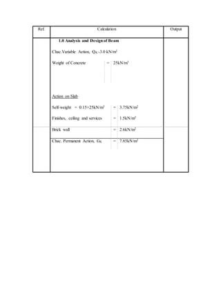
Action on slab
Selfweight=0.15x25=3.75 kN/m2
Finishes,ceiling and services=1.5 kN/m2
Brick wall =2.6 kN/m2
Permanent Loading, GK = 7.85kN/m
Variable Loading, QK = 3.0kN/m2
Design life = 50Years
Fire Resistance = R120
Exposure Cement = XC1
Materials:
Unit Weight of Concrete = 25kN/m3