This document discusses calculation methodologies for designing piping systems. It begins with an introduction to piping systems and their importance. It then discusses stresses piping systems experience from thermal expansion, weight, wind, and earthquakes. ASME B31.3 codes are commonly used for process piping design. The document presents methods to increase piping system flexibility through the use of pipe loops and expansion joints to absorb thermal expansion stresses. Pipe loops are preferable to expansion joints due to being simpler and more reliable.
Refinery mechanical piping systems a fundamental overviewChetan vadodariya
This paper is based on experience gained by the author in fabrication, design and installation in multinational
manufacturing, contracting and client companies in India, Saudi Arabia and Bahrain. Piping systems in
any oil refinery is the most critical mechanical hardware for the transportation of feed product i.e. crude oil to
processing units, process piping intra and inter process units and further movement of intermediate distillates
from one processing unit to another for the purpose of processing, blending, value addition and maximization of
recovery from feed stock to finish products. Pipelines are the ultimate transportation solution for despatch of final
product to storage tank farms and to the shipping terminal for internal consumption and for export. This paper lists
proven and established international design
Heat Load Calculations and Duct Design for Commercial Building G 2ijtsrd
The modern commercial or office building consists of the HVAC system which is Heating, Ventilation, Air conditioned. In this report, well going to identify the purpose and goals of HVAC system, describe HVAC types, describe HVAC parts and describe how this part works together or its working cycle. outsides to air conditioning there are ventilation systems like ceiling fan, fresh air supply and exhaust fan where ceiling fan is used is used to ventilate the air with rotating blades and exhaust fan is used to displace the inside air to the outside environment, fresh air supply is used to displace the inside air to the outside environment by supplying fresh air from the outside air. And also the design of duct by using the heat load calculations based on that how much amount of air to be carried out to gain the required cooling inside the area is determined and also creating the comfortable zone for the humans. R. Sateesh Kumar | J. Deepak | O. Srinivas | T. Prashanth ""Heat Load Calculations and Duct Design for Commercial Building G+2"" Published in International Journal of Trend in Scientific Research and Development (ijtsrd), ISSN: 2456-6470, Volume-3 | Issue-3 , April 2019, URL: https://www.ijtsrd.com/papers/ijtsrd23309.pdf
Paper URL: https://www.ijtsrd.com/engineering/mechanical-engineering/23309/heat-load-calculations-and-duct-design-for-commercial-building-g2/r-sateesh-kumar
Process piping fundamentals, codes and standards module 1BHARAT BELLAD
This document provides an overview of process piping fundamentals, codes, and standards. It covers topics such as pipe sizes, schedules, dimensions, materials, pressure ratings, and applicable design codes. The document is the first module in a nine-part course that introduces piping engineering concepts. It is divided into three chapters that cover piping systems basics, definitions and terminology, and relevant codes and standards like ASME B31.
The document discusses corrosion in pipelines used to transport oil and petroleum products. It describes different types of pipelines and how they are operated and regulated. It then focuses on corrosion as a major problem, the damage it causes, and methods to control it, specifically discussing cathodic protection which uses galvanic or impressed current methods to provide a protective current that prevents corrosion.
This document provides an overview of air-conditioning and mechanical ventilation (ACMV) systems. It discusses the main components and working principles of vapor-compression refrigeration cycles used in chilled water air-conditioning systems. The document also describes different types of air-conditioning systems, including various compressor types, and central chilled water system components and layouts. Optimization strategies for chilled water systems are presented, focusing on aspects like chiller efficiency, sizing, sequencing, and temperature reset controls.
This document outlines the scope of work for a plant design piping and equipment team. The team is responsible for creating piping layouts, equipment layouts, spacing considerations, equipment lists, pipe supports, isometrics, and general arrangement drawings. This is done using input documents such as plot plans, P&ID diagrams, piping specifications, and equipment data sheets. The document then provides details on specific types of piping (pump, exchanger, drum, etc.), equipment (pumps, heat exchangers, tanks, towers, compressors), and other design considerations (supports, input documents).
This document provides standards for piping design, layout, and stress analysis. It covers topics such as design and layout considerations including numbering systems, safety, clearance, pipe routing, valves, equipment piping, and stress analysis criteria. The standards are intended to replace individual company specifications and be used in existing and future offshore oil and gas developments. It references other NORSOK and international standards and does not cover all instrument control piping, risers, sanitary piping, or GRP piping.
Within industry, piping is a system of pipes used to convey fluids (liquids and gases) from one location to another. The engineering discipline of piping design studies the efficient transport of fluid
Industrial process piping (and accompanying in-line components) can be manufactured from wood, fiberglass, glass, steel, aluminum, plastic, copper, and concrete. The in-line components, known as fittings, valves, and other devices, typically sense and control the pressure, flow rate and temperature of the transmitted fluid, and usually are included in the field of Piping Design (or Piping Engineering). Piping systems are documented in piping and instrumentation diagrams (P&IDs). If necessary, pipes can be cleaned by the tube cleaning process.
"Piping" sometimes refers to Piping Design, the detailed specification of the physical piping layout within a process plant or commercial building. In earlier days, this was sometimes called Drafting, Technical drawing, Engineering Drawing, and Design but is today commonly performed by Designers who have learned to use automated Computer Aided Drawing / Computer Aided Design (CAD) software
pipe one of the main article that is used in our daily life.its being manufactured and used in industries in large scale. because of its large application and uses they are being manufactured in varies levels and types
This document provides guidelines for designing pipe racks and rack piping. It discusses pipe rack design criteria such as shapes, future space allowance, width, and clearances. It also covers pipe rack loading considerations. For rack piping, it outlines guidelines for positioning lines, spacing, routing larger lines and expansion loops. The document is intended to ensure pipe racks and piping arrangements are designed properly to support process units in a chemical plant.
IRJET-Experimental Study on Helical Tube Heat Exchanger by Varying Cross Sect...IRJET Journal
This document presents an experimental study on a helical tube heat exchanger. The study varies the cross-section of the tubes by adding nano particles like TiO2 and SiO2 to the working fluid. The performance of a helical coil heat exchanger is analyzed and compared to a straight tube heat exchanger based on parameters like log mean temperature difference (LMTD), heat transfer coefficient, and Reynolds number. The results show that a helical coil heat exchanger with nano particles added to the working fluid is more efficient, with its overall heat transfer coefficient increasing with mass flow rate.
This document provides an overview of piping fundamentals for fresher engineers. It discusses what piping is, piping components like pipes, fittings, valves and instruments. It covers piping layout considerations, stress analysis, supports, insulation, material selection and critical piping systems. The document uses examples and diagrams to illustrate piping system design, modeling in software, drafting of P&IDs, and compliance with codes like ASME and IBR.
Pipe racks are structures designed to support pipes, cables, and equipment in industrial facilities. The document discusses various design loads that should be considered when designing pipe racks, including dead loads, live loads, thermal loads, earthquake loads, wind loads, and load combinations. It provides guidance from codes like the IBC and standards like ASCE 7, and also discusses recommendations from industry sources like the PIP for determining and applying the different types of loads to the structural design of pipe racks.
This document discusses compact heat exchangers, including their types (plate and frame, brazed plate, welded plate, spiral, plate fin, printed-circuit, shell-and-tube), advantages of higher efficiency and lower cost/volume, limitations of fouling and lack of awareness, and design considerations like materials and operating limits. Compact heat exchangers can replace conventional heat exchangers due to their benefits. Security, environmental, and cost aspects are also covered.
Technical details of Energy Efficient HVAC Systemjayeshmahajan24
The document provides details on the design of an HVAC system for a commercial building. It discusses the indoor design conditions, daylight conditions, selection of double pane glass for the walls, use of autoclaved aerated concrete blocks and extruded polystyrene for the outer and inner walls. A hybrid VRF system is selected for cooling along with measures for indoor air quality, COVID-19 prevention, fan selection, basement design, fire safety systems and automation.
Stress Analysis Method , special points to be checked and understood by Piping engineers, Civil and Structural Engineers and especially by Stress Analysis Engineers.
Here's a presentation on piping engineering in PDF format, now available for all. This presentation covers the basics points of piping for our EPC industry. This presentation covers various aspects of piping engineering
TRUBORE offers the highest range of quality Agricultural Pipes & Fittings. TRUBORE is crafted to perfection with the highest rating of ISI with a wide range from 20mm to 250mm and working pressure mark and is available through a wide-spread network of around of 10kg/cm 2 , 6kg/cm 2 and 4kg/cm 2 as well as non-pressure 3500 dealers spread across the country. fittings.
This document provides an overview of key concepts in piping system design including:
1. It describes the basic components of a piping system including pipes, fittings, valves, instruments, supports, and discusses terminal connections and insulation.
2. It outlines the process of developing a piping system layout from defining flow requirements to creating piping and instrumentation diagrams (P&IDs) and 3D models.
3. It highlights important design considerations like accessibility, orientation, straight pipe lengths, drainage and ventilation.
This Presentation is about the basic fundamentals one needs to know to begin Piping Engineering. All the basic formulas and questions that are usually asked in interviews are answered in this presentation. Feel free to ask any doubts in the comments and iI may try my best to answer them for you.
This document provides guidance on selecting and designing fiberglass piping systems. It discusses preliminary pipe sizing based on flow rate and pipe diameter. For detailed sizing, it describes methods to calculate pressure loss due to fluid friction and fittings using equations like Darcy-Weisbach that factor in parameters like pipe roughness, diameter, fluid properties and velocity. It also discusses flow regimes like laminar, turbulent and transitional, and how to determine friction factors using Colebrook or other equations based on the Reynolds number.
Pipes are used to transport liquids and gases and are made from various materials like steel, plastic, copper, etc. Common pipe types include seamless, ERW, and CDW pipes. Pipes are designed based on thickness calculations to withstand internal and working pressures. Bends in pipes are formed using methods like ram bending and mandrel bending. Forces like pressure, mass flow, and velocity cause stresses on bends. Head loss occurs in bends due to friction and is quantified using loss coefficients. Pipes and bends have wide applications in industries, buildings, households, and infrastructure.
Abstract Chimneys are very important structures for the emission of poisonous gases in power plants. After realising the urgent need to
restrict the pollution levels, chimney height is being rapidly increased. So most of the chimneys are tall slender structures which
fail due to wind excitation The present study discusses the dynamic behaviour of tall chimneys. Reinforced concrete chimney of
275m high, which is located in warora, Maharastra is taken for the present study. The objective of this project is to study the
change in the stress pattern due to presence of flue holes and also to carry out the influence of along wind and across wind effects
on the height of chimney for different wind speed and location. The analyse of chimney is carried out by developing a three
dimensional model created with plate elements using STADD Pro. The stress concentrations in the flue duct in the chimney have
been studied.
Keywords: Tall Slender, Warora, Maharastra, Flue Holes, STADD Pro, Stress Concentration
This document provides guidance on designing pipe hangers and supports. It discusses determining hanger locations based on pipe size and configuration. It describes calculating hanger loads based on the weight of pipe, fittings, valves, and insulation. It also addresses calculating thermal movement of piping at hanger locations. The document provides information on selecting appropriate hangers based on the loads and movements, including spring hangers. It includes sample problems demonstrating how to apply the guidance. An extensive section lists the weights of common piping materials to aid in load calculations. The document is intended as a reference for engineers involved in pipe hanger and support design.
Remaining life assessment of refinery furnace tubes using finite element methodBarhm Mohamad
Crude oil heater 9Cre-1Mo steel tubes from a refinery plant were studied, after 5 years of service at nominally 650 Cº and 3 bar, to predict their remnant lives. The investigation included dimensional, hardness and tensile measurements in addition to accelerated stress rupture tests between 650 Cº and 700 Cº and microstructural examination. Tube specimens were taken from two sections, the overheated side and the side which only saw the nominal operating temperature. The method employed involved the prediction of the increase in temperature with increasing sediment deposition during the operating life times using an FEM model. In addition the predicted temperatures are used to derive appropriate creep properties at relevant temperatures in a 3D pipe FEM creep analysis to predict the pipe deformation rate. All compare well with the actual service exposed pipe measurements and layer deposition. The overheated side revealed a small loss of creep strength in a stress rupture test. A layer of sediment (appr. 10 mm thickness) consisting basically of sintered carbon (coke) spread over the inside of the tube was acting as a thermal barrier causing the temperature to rise above 650 Cº. Analysis for the overheated side predicted an upper bound temperature of 800 Cº and a life of about 50 h suggesting that failure by creep rupture could occur rapidly in the sediment region.
This document provides a summary of the history and technology of piping. It discusses ancient uses of piping in Mesopotamia and Rome, as well as modern standards and codes governing piping systems in the United States, North America, and Europe. Key topics covered include pipe materials, fabrication, mechanical properties, stresses on pipes from internal and external pressures, corrosion protection, and repair techniques. The document traces the evolution of piping from its early uses to its widespread applications today.
ASME B31.3 TRAINING COURSE
The lack of commentary, or historical perspective, regarding the ASME B31.3 Code requirements for process piping design and construction is an obstacle to the designer, manufacturer, fabricator, supplier, erector, examiner, inspector, and owner who wants to provide a safe and economical piping system. This intensive five-day course, through the use of hundreds of examples shown and personal experiences of the instructors demonstrates how the ASME B31.3 Code has been correctly and incorrectly applied. This seminar explains the principal intentions of the Code and why the Code is not a handbook. Attendees come away from this seminar with a clear understanding of how piping systems fail and what the Codes require the designer, manufacturer, fabricator, supplier, erector, examiner, inspector and owner to do to prevent such failures. The focus of the seminar is to enhance participants understanding and application of the ASME B31.3 Code. Instruction is further enhanced by in-class problem solving, directly applying the rules and equations of the ASME B31.3 Codes for specific design and operating conditions to illustrate correct applications.
Course Outlines:
Introduction to ASME B31.3
ASME B31.3 Scope and Definitions
Design Considerations & Criteria
Pressure Design of Piping Components
Design – Fluid Service Requirements & Standards for Piping Components Standards
Design – Fluid Service Requirements for Piping Joints
Design – Flexibility and Support
Bellows Expansion Joints
Design Systems
Materials
Fabrication, Assembly & Erection
Inspection, Examination & Testing
Who Should Attend:
Fresh graduates and piping engineers and designers who need an understanding of the requirements for compliance and the trends of Code changes for piping design and analysis, fabrication, examination, and testing
Upon completion of this course, you will be able to:
Identify the responsibilities of personnel involved in the design, fabrication, assembly, erection, examination, inspection, and testing of process piping
Describe the scope and technical requirements of the ASME B31.3 Code
Apply and implement the quality requirements that are defined in the ASME B31.3 Code
Special Features & Requirements:
Bring a note book, a pen and a calculator
Printed notes of the lecture, as well as additional notes, will be provided
Course Dates and Prices:
The course duration (15 hours), starts every Monday to Friday at 6:00pm to 9:00 pm)
Fees are 399 CADs for 1 person
#Little_PEng
https://www.littlepeng.com/asme-b31-3-training-course
This document provides information about pipe stress analysis and thermal expansion. It discusses the objectives of stress analysis to ensure piping structural integrity and allowable load limits. Thermal expansion due to temperature changes is a key consideration, as it can cause stresses and loads on piping components. The document outlines the various loads on piping from weight, temperature changes, and occasional events. It also describes the steps of stress analysis and provides examples of calculating thermal expansion using equations and charts.
Design and Analysis of an Air Conditioning Duct Using Equal Friction MethodIRJET Journal
This document describes the design and analysis of an air conditioning duct system using the equal friction method. It begins with an introduction to central air conditioning systems and the importance of properly designing ductwork to minimize pressure losses and costs while providing optimal indoor air quality and comfort. The document then outlines the specific steps involved in the equal friction duct design method, which involves setting the duct dimensions so that the pressure drop per unit length is equal across all ducts. The rest of the document provides an example application of this method to size ducts for a central air conditioning system serving an area of 72.2 square meters. Tables and calculations are presented to determine the equivalent diameter, dimensions, air flow rates, velocities and pressure losses for each duct section
1) The document analyzes stress on buried pipelines using CAESAR II software. A pipeline system is modeled and different load cases are applied including operating, sustained, and expansion loads.
2) Stress results like axial stress, bending stress, torsion stress and hoop stress are obtained from the software. The maximum stress is below the allowable stress specified in the ASME B31.1 code.
3) Finite element analysis is also carried out using ABAQUS to model the soil-pipeline interaction. The maximum stress is found at the top and bottom of the pipeline due to vertical static loads.
This document is a project report on piping stress analysis submitted by three students - Adwait A. Joshi, Robin T. Cherian, and Girish R. Rao - to the University of Mumbai in partial fulfillment of their Bachelor of Mechanical Engineering degree requirements. It was completed under the guidance of their internal project guide Prof. Ms. R. R. Easow at Sardar Patel College of Engineering, with external guidance from Prof. A. S. Moharir of IIT Bombay's Piping Engineering Cell. The report introduces piping stress analysis, outlines the objectives and scope of analyzing stresses in piping systems, and describes how loads are classified and their effects on piping stresses
This document discusses the fundamentals of piping design for geothermal fields. It covers key topics such as:
- Design criteria including process parameters, codes, and deliverables
- Piping design procedures including fluid characteristics, separator location, pipe types and codes
- Equations for calculating pressure drop, heat losses, and electric power output of steam pipes
The overall aim is to safely and economically transport geothermal fluids from production wells to the power plant via piping systems that consider installation and lifetime costs, pressure losses, stresses, and other factors.
This document discusses key considerations for designing a water distribution system including:
1) The type of water flow (continuous or intermittent) and method of distribution (gravity or pumping).
2) Estimating future demand based on population growth and industrial/firefighting needs.
3) Factors that influence pipe sizing such as hydraulic gradient, flow velocity, and design life.
4) Common pipe joint types like butt-welded, socket-welded, threaded, grooved, flanged, and compression joints and their relative costs, strengths, and installation complexity.
Liquid Piping Systems, Minor Losses: Fittings and Valves in Liquid Piping Systems, Sizing Liquid Piping Systems; Fluid Machines (Pumps) and Pump–Pipe Matching, Design of Piping Systems complete with In-Line or Base-Mounted Pumps
IRJET- Review on Various Practices on Fatigue Analysis of Nuclear Power Plant...IRJET Journal
This document reviews various practices for fatigue analysis of piping components in nuclear power plants. It discusses causes of fatigue failures in piping components under variable loading conditions. The key points discussed include:
1) Fatigue is a major cause of failure in piping components of nuclear power plants. Variable loading conditions make pipes and elbows more susceptible to cracking.
2) Several experimental and numerical studies have been conducted to understand fatigue crack growth in materials like steel and zircaloy used in nuclear plant piping. Factors influencing crack growth rate and traditional analysis methods are summarized.
3) Common materials used in power plant piping include low-alloy steels, stainless steels, nickel alloys,
Recent Advancements in Piping industry and Piping materials.Asheesh Padiyar
A brief overview of the new technologies that are available for piping engineers to know the latest advancements in piping materials . As a chemical engineer, it is essential to know about the various piping systems and technologies associated with it, in order to have a better understanding of their project/ process/ installing/ commissioning of the plants/ refineries.
IJRET : InIJRET : International Journal of Research in Engineering and Technology is an international peer reviewed, online journal published by eSAT Publishing House for the enhancement of research in various disciplines of Engineering and Technology. The aim and scope of the journal is to provide an academic medium and an important reference for the advancement and dissemination of research results that support high-level learning, teaching and research in the fields of Engineering and Technology. We bring together Scientists, Academician, Field Engineers, Scholars and Students of related fields of Engineering and Technologyternational Journal of Research in Engineering and Technology is an international peer reviewed, online journal published by eSAT Publishing House for the enhancement of research in various disciplines of Engineering and Technology. The aim and scope of the journal is to provide an academic medium and an important reference for the advancement and dissemination of research results that support high-level learning, teaching and research in the fields of Engineering and Technology. We bring together Scientists, Academician, Field Engineers, Scholars and Students of related fields of Engineering and Technology
Simulative analysis of tube hydroforming processeSAT Journals
Abstract The tube hydro forming process (THF) is an unconventional metal forming process, where in tube is deformed internally and thus it is forced to expand and conform to the shape of the surrounding die. The performance of this process depends on various parameters like internal pressure, axial loading etc. For FEA simulation, it requires proper combination of material selection, part design and boundary conditions. The estimated process parameters are optimized using FEA simulations. In this work, free bulge shaped tube die was modeled by using Auto CAD. Subsequently, the processes were simulated using DEFORM-3D and it has been verified with experimental work under proper boundary and loading condition. Process parameters study also been conducted. It has been found that the estimated process parameters, developed branch height and the wall thickness distribution along different planes are in good coincidence with experimental results. Keywords: Tube hydroforming, Free bulge forming, DE-FORM Software, EN-31, Axial feeding, internal fluid pressure, FEA Simulation, loading path.
Design & Stress Analysis of a Cylinder with Closed ends using ANSYSIJERA Editor
The significance of the title of the project comes to front with designing structure of the pressure vessel for static loading and its assessment by ANSYS , is basically a project concerned with design of different pressure vessel elements such as shell, Dish end ,operating manhole ,support leg based on standards and codes ; and evolution of shell and dish end analysed by means of ANSYS .The key feature included in the project is to check the behaviour of pressure vessel in case of fluctuating load . The procedural step includes various aspects such as selecting the material based on American Society of Mechanical Engineers (ASME) codes ,and then designing on the standards procedures with referring standard manuals based on ASME .Further we have included the different manufacturing methods practice by the industries and different aspects of it .
This document provides an overview and comparison of three common heat tracing systems: thermal fluid, electric, and steam. It discusses the history and evolution of each system from the early 1900s to present day. The key developments include more sophisticated control methods for thermal fluid systems, improvements to electric tracing that enabled automatic temperature controls, and efforts to reduce heat output from steam systems to better regulate temperature. The document also notes some basic comparisons between the merits and limitations of each system and outlines factors to consider in a tracing system analysis, such as application needs, performance, energy efficiency, and installation costs.
Modelling and Stress Analysis of the Pig Loop Module of a Piping System.IJRES Journal
The failure of any piping system depends on the stress analysis that was performed during the engineering design of the piping system. In designing the pig loop of a submarine manifold to be used in area Y of Niger delta in Nigeria, a proper analysis of the load to which the system could be subjected was carried out using a stress analysis software - ''Triflex piping solutions.'' We employed ASME B31.8 piping code. Various stress values and deflections were analysed at each node to ensure that the design will be on a safe operating condition. Stress utilization was checked for hoop and longitudinal stresses for various scenarios and the worst case scenario was determined. The maximum stress utilization for the worst case scenario was found to be within the limit and thereby meeting with the safety requirement.
Suction Duct Optimization for Fume Extraction SystemIRJET Journal
1. The document discusses optimization of the design of suction ducts for fume extraction systems. It compares the conventional design to a proposed new design using simulation software.
2. The simulation results show the conventional design has non-uniform extraction across inlets and reduced pressure and velocity at inlets further from the blower. The proposed design uses individual paths for each inlet with smooth junctions, improving flow uniformity.
3. Analysis of the mass flow rates across inlets found the proposed design increased uniformity compared to the conventional design, allowing more efficient extraction with the same blower capacity. The proposed design should be considered over the conventional to improve system efficiency.
A recommended-approach-to-piping-flexibility-studies-to-avoid-compressor-syst...Adeel Jameel
This document recommends an approach for piping flexibility studies when responsibility for the piping design is shared between a compressor packager and an engineering company. The common practice of limiting analyses to individual scopes and using anchor points and allowable loads at the boundary has limitations. Instead, it recommends overlapping the modeling scopes to account for interactions. Both parties should include a small portion of the other's piping to accurately capture the response of the complete system and avoid overly conservative designs.
Pressure Loss Optimization of a Sprinkler ValveOmar Wannous
This document summarizes a bachelor's thesis on optimizing pressure loss in a sprinkler valve. The thesis involved researching fluid mechanics principles, high pressure water mist systems, and classification standards. It then conducted an extensive feasibility study and CFD simulations on the valve's design. This uncovered deviations from theoretical predictions due to simplifying assumptions. Several potential redesigned concepts were simulated, with the best concept upgraded and field tested. The final optimized design achieved the project's goal of reducing pressure loss through the valve, improving water mist system functionality for land and marine applications.
IRJET- Design, Modeling and Analysis of a Vacuum Chamber for High Speed T...IRJET Journal
This document describes the design, modeling, and analysis of a vacuum chamber for testing high speed turbine blades. Key points:
- A vacuum chamber was designed in Pro/Engineer to test rotors up to 17,500 lbs, 67 inches in diameter, at speeds up to 60,000 RPM.
- Structural, modal, and fatigue analysis of the vacuum chamber was performed in ANSYS using materials like stainless steel, aluminum alloy, brass and acrylic.
- The vacuum chamber was modeled, meshed, and boundary conditions like pressure were applied. Von Mises stress, strain, and displacement results were obtained and evaluated.
- Thermal analysis of the vacuum chamber was also conducted in AN
Eugene f. megyesy-pressure_vessel_handbook_12th editionGowtham M
The document is an introduction to the Pressure Vessel Handbook, which provides concise summaries and essential information for designing and constructing pressure vessels. It compares the scope and purpose of the Pressure Vessel Handbook to the ASME Boiler and Pressure Vessel Code. The Handbook covers carbon steel pressure vessels made by welding, utilizing the most economical and practical construction methods according to Code rules. It aims to make information easily accessible, while the Code establishes broader rules and does not serve as a design handbook. The Handbook is updated every three years to reflect changes to the Code and industry developments.
Piping For Cooling Water Circulation between Cooling Tower and CondenserIJSRD
In thermal power plant, as we know that exhaust steam from turbine goes to heat recovery unit and from there the exhaust stem goes to the condenser to condense. In shell and tube heat exchanger, cooling water as a cooling medium running inside the tubes whereas steam is inside the shell. So to have sufficient amount of cooling water, we require continuous flow of water from the cooling tower. Our main project aim is to provide a piping between condenser and cooling tower. So in this particular project, we will make basic documents such as pfd, p&id, plot plan, equipment layout, piping ga drawing, isometrics, mto, piping specifications, pump specification, calculations, and stress analysis etc.
Electric vehicle and photovoltaic advanced roles in enhancing the financial p...IJECEIAES
Climate change's impact on the planet forced the United Nations and governments to promote green energies and electric transportation. The deployments of photovoltaic (PV) and electric vehicle (EV) systems gained stronger momentum due to their numerous advantages over fossil fuel types. The advantages go beyond sustainability to reach financial support and stability. The work in this paper introduces the hybrid system between PV and EV to support industrial and commercial plants. This paper covers the theoretical framework of the proposed hybrid system including the required equation to complete the cost analysis when PV and EV are present. In addition, the proposed design diagram which sets the priorities and requirements of the system is presented. The proposed approach allows setup to advance their power stability, especially during power outages. The presented information supports researchers and plant owners to complete the necessary analysis while promoting the deployment of clean energy. The result of a case study that represents a dairy milk farmer supports the theoretical works and highlights its advanced benefits to existing plants. The short return on investment of the proposed approach supports the paper's novelty approach for the sustainable electrical system. In addition, the proposed system allows for an isolated power setup without the need for a transmission line which enhances the safety of the electrical network
Prediction of Electrical Energy Efficiency Using Information on Consumer's Ac...PriyankaKilaniya
Energy efficiency has been important since the latter part of the last century. The main object of this survey is to determine the energy efficiency knowledge among consumers. Two separate districts in Bangladesh are selected to conduct the survey on households and showrooms about the energy and seller also. The survey uses the data to find some regression equations from which it is easy to predict energy efficiency knowledge. The data is analyzed and calculated based on five important criteria. The initial target was to find some factors that help predict a person's energy efficiency knowledge. From the survey, it is found that the energy efficiency awareness among the people of our country is very low. Relationships between household energy use behaviors are estimated using a unique dataset of about 40 households and 20 showrooms in Bangladesh's Chapainawabganj and Bagerhat districts. Knowledge of energy consumption and energy efficiency technology options is found to be associated with household use of energy conservation practices. Household characteristics also influence household energy use behavior. Younger household cohorts are more likely to adopt energy-efficient technologies and energy conservation practices and place primary importance on energy saving for environmental reasons. Education also influences attitudes toward energy conservation in Bangladesh. Low-education households indicate they primarily save electricity for the environment while high-education households indicate they are motivated by environmental concerns.
Design and optimization of ion propulsion dronebjmsejournal
Electric propulsion technology is widely used in many kinds of vehicles in recent years, and aircrafts are no exception. Technically, UAVs are electrically propelled but tend to produce a significant amount of noise and vibrations. Ion propulsion technology for drones is a potential solution to this problem. Ion propulsion technology is proven to be feasible in the earth’s atmosphere. The study presented in this article shows the design of EHD thrusters and power supply for ion propulsion drones along with performance optimization of high-voltage power supply for endurance in earth’s atmosphere.
Gas agency management system project report.pdfKamal Acharya
The project entitled "Gas Agency" is done to make the manual process easier by making it a computerized system for billing and maintaining stock. The Gas Agencies get the order request through phone calls or by personal from their customers and deliver the gas cylinders to their address based on their demand and previous delivery date. This process is made computerized and the customer's name, address and stock details are stored in a database. Based on this the billing for a customer is made simple and easier, since a customer order for gas can be accepted only after completing a certain period from the previous delivery. This can be calculated and billed easily through this. There are two types of delivery like domestic purpose use delivery and commercial purpose use delivery. The bill rate and capacity differs for both. This can be easily maintained and charged accordingly.
Digital Twins Computer Networking Paper Presentation.pptxaryanpankaj78
A Digital Twin in computer networking is a virtual representation of a physical network, used to simulate, analyze, and optimize network performance and reliability. It leverages real-time data to enhance network management, predict issues, and improve decision-making processes.
Generative AI Use cases applications solutions and implementation.pdfmahaffeycheryld
Generative AI solutions encompass a range of capabilities from content creation to complex problem-solving across industries. Implementing generative AI involves identifying specific business needs, developing tailored AI models using techniques like GANs and VAEs, and integrating these models into existing workflows. Data quality and continuous model refinement are crucial for effective implementation. Businesses must also consider ethical implications and ensure transparency in AI decision-making. Generative AI's implementation aims to enhance efficiency, creativity, and innovation by leveraging autonomous generation and sophisticated learning algorithms to meet diverse business challenges.
https://www.leewayhertz.com/generative-ai-use-cases-and-applications/
Null Bangalore | Pentesters Approach to AWS IAMDivyanshu
#Abstract:
- Learn more about the real-world methods for auditing AWS IAM (Identity and Access Management) as a pentester. So let us proceed with a brief discussion of IAM as well as some typical misconfigurations and their potential exploits in order to reinforce the understanding of IAM security best practices.
- Gain actionable insights into AWS IAM policies and roles, using hands on approach.
#Prerequisites:
- Basic understanding of AWS services and architecture
- Familiarity with cloud security concepts
- Experience using the AWS Management Console or AWS CLI.
- For hands on lab create account on [killercoda.com](https://killercoda.com/cloudsecurity-scenario/)
# Scenario Covered:
- Basics of IAM in AWS
- Implementing IAM Policies with Least Privilege to Manage S3 Bucket
- Objective: Create an S3 bucket with least privilege IAM policy and validate access.
- Steps:
- Create S3 bucket.
- Attach least privilege policy to IAM user.
- Validate access.
- Exploiting IAM PassRole Misconfiguration
-Allows a user to pass a specific IAM role to an AWS service (ec2), typically used for service access delegation. Then exploit PassRole Misconfiguration granting unauthorized access to sensitive resources.
- Objective: Demonstrate how a PassRole misconfiguration can grant unauthorized access.
- Steps:
- Allow user to pass IAM role to EC2.
- Exploit misconfiguration for unauthorized access.
- Access sensitive resources.
- Exploiting IAM AssumeRole Misconfiguration with Overly Permissive Role
- An overly permissive IAM role configuration can lead to privilege escalation by creating a role with administrative privileges and allow a user to assume this role.
- Objective: Show how overly permissive IAM roles can lead to privilege escalation.
- Steps:
- Create role with administrative privileges.
- Allow user to assume the role.
- Perform administrative actions.
- Differentiation between PassRole vs AssumeRole
Try at [killercoda.com](https://killercoda.com/cloudsecurity-scenario/)
AI for Legal Research with applications, toolsmahaffeycheryld
AI applications in legal research include rapid document analysis, case law review, and statute interpretation. AI-powered tools can sift through vast legal databases to find relevant precedents and citations, enhancing research accuracy and speed. They assist in legal writing by drafting and proofreading documents. Predictive analytics help foresee case outcomes based on historical data, aiding in strategic decision-making. AI also automates routine tasks like contract review and due diligence, freeing up lawyers to focus on complex legal issues. These applications make legal research more efficient, cost-effective, and accessible.
Introduction- e - waste – definition - sources of e-waste– hazardous substances in e-waste - effects of e-waste on environment and human health- need for e-waste management– e-waste handling rules - waste minimization techniques for managing e-waste – recycling of e-waste - disposal treatment methods of e- waste – mechanism of extraction of precious metal from leaching solution-global Scenario of E-waste – E-waste in India- case studies.
VARIABLE FREQUENCY DRIVE. VFDs are widely used in industrial applications for...PIMR BHOPAL
Variable frequency drive .A Variable Frequency Drive (VFD) is an electronic device used to control the speed and torque of an electric motor by varying the frequency and voltage of its power supply. VFDs are widely used in industrial applications for motor control, providing significant energy savings and precise motor operation.
Discover the latest insights on Data Driven Maintenance with our comprehensive webinar presentation. Learn about traditional maintenance challenges, the right approach to utilizing data, and the benefits of adopting a Data Driven Maintenance strategy. Explore real-world examples, industry best practices, and innovative solutions like FMECA and the D3M model. This presentation, led by expert Jules Oudmans, is essential for asset owners looking to optimize their maintenance processes and leverage digital technologies for improved efficiency and performance. Download now to stay ahead in the evolving maintenance landscape.
1. International Journal of Engineering Research and General Science Volume 2, Issue 6, October-November, 2014
ISSN 2091-2730
596 www.ijergs.org
Calculation Methodologies for The Design of Piping Systems
Mr. Suyog U. Bhave.
M.E. Student, D. Y Patil Institute of Engineering and Technology, Pune, India.
Principal Piping Engineer, Petrofac Engineering India Pvt. Ltd, Mumbai, India
Mail: Suyog.bhave@gmail.com
Abstract- Piping systems are constantly present in industrial facilities, being in some cases associated with the transport of fuels,
processing of crude oils and chemical plants. Due to the nature of those fluids, the design of the piping system that transports them is a
task of great responsibility, which must follow codes and standards to guarantee the system’s structural integrity. Many times the
piping systems operate at a temperature higher than the temperature at which they are assembled, leading to the thermal expansion of
the system’s pipes and since no piping system is free to expand, the thermal expansion will lead to stresses. Besides the stresses
caused by thermal expansion, the studied systems will also are subjected to constant loads caused by their weight, as well as
occasional loads like wind, earthquake. In this perspective, calculation methodologies were developed in order to do quick analysis of
the most common configurations, according to the codes like ASME B31.3, allowing that way improvements on the flexibility of the
projected systems.
Although the methodology developed may only be used in simple systems and gives very conservative results, in practical cases it can
be used to analyse complex systems, by dividing them in simpler cases.
[6, 8, 10]
Keywords
Piping Systems, Flexibility, Stress Analysis, Thermal Expansion, ASME B31.3, design methodology, expansion loop.
I. Introduction
The first piping systems were constructed between 3000 b.C. and 2000 b.C. in the ancient Mesopotamia to be used on the irrigation of
large areas of cultivated land. Initially used in agriculture, due to the growing need to cultivate larger areas, piping systems also had a
crucial role in the development of big cities and during the industrial revolution with the discovery of steam power. Piping systems
also turned out to be essential in the exploration of oil.
In the present civilization, piping systems are constantly present, either in residential and commercial buildings, either in industrial
facilities. In oil refineries and others industrial process plants, pipelines represent between 25% and 50% of the total cost of the
facilities.
Since piping systems are associated with facilities of high degree of responsibility, stress analysis represent a fundamental stage of the
piping design, in order to prevent failures and cause of accidents. Taking into account that piping systems are subjected to multiple
loads, stress analysis represents a complex task. Besides the stresses caused by the piping weight, fluids and isolation, piping systems
are also subjected to temperature changes, internal and external pressure, and occasional events such as water hammer, wind and
earthquakes.
Due to the temperature variations that occur in piping systems, between the installation and operation temperatures, they will be
subject to expansion and contraction. In the general terms, both contraction and expansion are called thermal expansion. Since every
piping system has restrictions that prevent the free expansion, thermal expansions will always create stresses, but, if the system is
flexible enough, the expansion may be absorbed without creating undue stresses that may damage the system, the supports and the
equipment to which the pipes are connected.
One of the greatest challenges in the pipe stress analysis is to provide the system enough flexibility to absorb the thermal expansions.
Even nowadays, that pipe stress analysis covers much more than flexibility analysis, it still is one of the main tasks of the engineers
that work in this area. Many times due to the inexistence of a quick method that allows a verification of the flexibility of projected
systems, they turn out to be too stiff or too flexible.
Engineers constantly face the need to minimize the costs and at the same time obtain a system with enough flexibility, without
sacrificing the security requirements. The shortest the system, the lowest the price, since it will use less material, but this configuration
will have flexibility problems in the majority of the cases, due to the incapacity to absorb thermal expansion. On the other hand,
systems that are too long may have problems due to pressure drop. The increase of a system’s flexibility may be obtain due to the
2. International Journal of Engineering Research and General Science Volume 2, Issue 6, October-November, 2014
ISSN 2091-2730
597 www.ijergs.org
changes in direction, although, in the cases where the flexibility obtained that way isn’t enough, additional flexibility may be obtain
using pipe loops and expansion joints. The attention given to pipe stress analysis has increased in the last decades, due to the high
safety requirements of the modern process plants. For that reason, the access to an efficient computer program, such as CAESAR II,
ANSYS, AUTOPIPE to perform the stress calculations, reduces the design costs, since it decreases the time necessary to perform the
analysis. In order to prove the structural integrity of a piping system, it is necessary to follow the procedures and specifications of the
piping codes. There are several codes that involve the design of piping systems, but the ones more often used are the ASME B31
Codes. However there are design limitations stated in Codes, these are needed to be consider during analysis assumptions and
deciding methodology.
It is extremely important to make a correct design of piping systems, avoiding their failure, which may cause huge material damage
and even loss of human lives. The objective of this paper is to present calculation methodologies for the design of piping systems.
[1, 4, 5, 8]
II. CODES AND STANDARDS
In order to satisfy the safety requirements, local regulations, design constraints of Client, piping systems have to be designed and built
according to determinate codes and standards.
In the United States, the American Society of Mechanical Engineers (ASME) has assumed the leadership in the formation of
committees that have elaborated The Piping Code. The Piping Code is constituted by a set of requirements that assure a correct and
safe operation of the piping systems. The code ASME B31 establishes the allowable stresses, the design, the fabrication, the erection,
the tests, the fatigue resistance and the operation for non-nuclear piping systems. For this paper we are particularly interested in the
facilities covered by the codes B31.3.
ASME B31.3 Process Piping: For piping systems used in process plants, such as petrochemical plants, this is the code that covers
almost all the requirements to design, erection, testing of piping systems.The stress analysis requirements are detailed in this code can
be applied to all the plants designed according to this Code. This Code is constantly improved considering latest industrial trend and
feedback from various committee members, consultants and industrial operation groups.
There are other Codes and Standards from different countries like UK, EU, Japan which also are used and applied to the stress
analysis. There are consultancy practices which provide guidelines and rules to design piping system.
[3, 6, 8]
III. THERMAL EXPANSION AND FLEXIBILITY
Most of the piping systems work at temperatures higher than the installation temperature. This temperature raise, will lead to the
thermal expansion of the pipes, which for the cases of interest of this paper will always be metallic pipes. The thermal expansion of a
material is evaluated by the thermal expansion coefficient 𝛼. The thermal expansion of a pipe may be calculated by the following
expression:
Δ = 𝛼𝐿 (1)
where𝐿 is the pipe length at the reference temperature (usually the installation temperature).
If a piping system does not have enough flexibility, in order to compensate the thermal expansions, the stresses originated may
damage the system, as well as the equipment to which it is connected.
Fig. 1
Consider piping connecting from Tank T1 to Tank T2. If the piping is straight as shown in the Fig. 1 and fluid with higher temperature
flow though the piping, the section of pipe between T1 and T2 will expand. However, there is no space to expand and result in high
loads on the nozzles. However if we provide the loop as shown in the Fig. 2, the nozzle loads can be decreased.
In this case, flexibility may be increased adding additional sections of pipe perpendicularly to the original section, to absorb the
expansion that is the principle of pipe loops. In other words, by using pipe loops, the thermal expansion is absorbed by the bending of
the perpendicular sections of pipe.
3. International Journal of Engineering Research and General Science Volume 2, Issue 6, October-November, 2014
ISSN 2091-2730
598 www.ijergs.org
There are several methods to increase systems’ flexibility, being often used the installation of pipe loop as depicted in Fig. 2. In some
cases, due to spatial constrains, expansion joints are the alternative to the installation of pipe loops. There are several types of
expansion joints, but all of them are elements much more sophisticated than the pipe loops, which are nothing more than additional
sections of pipe. In addition, expansion joints are subjected to breakdowns and require maintenance. For these reasons, the design of
pipe loops to increase the systems flexibility is preferable to the use of expansion joints.
Fig.2 – Pipe loop
Besides the use of pipe loops being much simpler than the use of expansion joints, it still matters to know the best pipe loop
configurations, in order to maximize its potential to increase flexibility.
In first place, in order to keep forces and moments balanced, the loop as depicted in Fig. 2 must be symmetric. Concerning the relation
between the loop dimensions, there is some divergence between companies, while some established design guidelines defining 𝐿3=𝐿2,
other defined the best configuration as the one that follows the relation:
𝐿3 = 1/2𝐿2 (2)
To calculate the length 𝐿2 necessary to absorb the thermal expansion without damaging the pipe, following expression, which derives
from the guided cantilever method, may be used:
𝐿2 =
3EhDΔ
SA
(3)
where𝐸ℎ is the modulus of elasticity of the material at the operation temperature, 𝐷 is the outer diameter of the pipe and 𝑆 𝐴 is the
allowable expansion stress.
Relatively to loops locations, they must be centered between anchorages, 𝐿1 = 𝐿5. In cases that is not possible to center the loop, it
should be tried that the pipe sections, at each side of the loop has their dimensions as close as possible.
Besides the anchorages at the ends of the pipe loops, in many cases there are also intermediate guides and vertical supports. The
function of the vertical supports is to support the pipes’ weight, assuring the allowable pipe span. The guides are used to control the
thermal expansion, assuring that the loops play their role correctly, since they direct the expansion to the sections defined by the tubes
of length 𝐿2 and 𝐿4.
[5, 9, 11, 12]
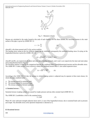
IV. CODE STRESS REQUIREMENTS
According to the Codes ASME B31.3, only the maximum stresses are calculated, which is implicit in the stress intensification factors
(SIF) that derive fundamentally from fatigue tests.Code requirements are specified with the cautions and limitations which need to be
carefully considered while designing piping system. Even Code specifies the actions when the condition cannot fully comply with
Code requirements. The expressions to calculate the stresses presented in the ASME B31.3, are only influenced by the moments,
ignoring the forces. This is due to the fact that the stresses originated by forces are usually too low when compared with the stresses
originated by moment. Before calculate the stresses, the moments have to be reoriented accordingly to the planes of the component
that is under analysis, due to the different SIF of each direction. The SIF calculation is the most crucial step and careful considerations
are required. The in plane and out of plane moment need to be considered. The stresses developed are more in the cases like direction
change, inside diameter change, sudden obstructions. The example of elbow is shown in Fig. 3, shows inner and outer plane
moments.
4. International Journal of Engineering Research and General Science Volume 2, Issue 6, October-November, 2014
ISSN 2091-2730
599 www.ijergs.org
Fig. 3 – Moments in bends
Stresses are calculated in the nodes located at the ends of each element. For the shear stresses, the maximum tension in the outer
surface of the pipe, is given by (ASME B31.3):
𝜏 = 𝑆𝑡 =
𝑀 𝑇
2𝑍
(4)
where𝑀 𝑇 is the shear moment and 𝑍 is the section modulus.
The bending stress acting on the two different planes can be combined, consequently the combined bending stress 𝑆 𝑏 acting on the
longitudinal direction is given by (ASME, B31.3):
𝑆 𝑏 = iiMi
2
+ ioMo 2
/ Z(5)
where𝑀𝑖 and 𝑀 𝑜, are respectively the inner and outer plane bending moments, and 𝑖𝑖 and 𝑖 𝑜 are respectively the inner and outer plane
stress intensification factors (Fig- 3).
The flexibility analysis is done by the comparison between the combined effect of multidimensional tensions and the allowable stress.
The ASME B31.3 codes use the Tresca criterion to obtain the combined tension effect 𝑆, also called expansion stress:
𝑆 𝐸 = Sb
2
+ 4St
2
(6)
According to the ASME B31.3 Code, the stresses to which a piping system is subjected may be separate in three main classes, for
which the codes establish limits:
A) The stresses caused by sustained loads
B) The stresses caused by occasional loads
C) The stresses caused by thermal expansion.
A. Sustained stresses :
Sustained stresses in piping systems are caused by weight, pressure and any other constant load (ASME B31.3).
The ASME B31.3,establishes a limit to the sustained stress:
𝑆 ≤ 𝑆ℎ 𝑊 (7)
Where W is the weld joint strength reduction factor and 𝑆 𝐿 is sum of the longitudinal stresses, due to sustained loads such as pressure
and weight. The allowable stress at the operation temperature is denoted as 𝑆ℎ.
B. Occasional stresses
5. International Journal of Engineering Research and General Science Volume 2, Issue 6, October-November, 2014
ISSN 2091-2730
600 www.ijergs.org
Occasional stresses are caused by occasional events, such as water hammer, earthquakes and wind.
According to ASME B31.3,𝑆 𝐿 + 𝑆 𝑜𝑐 should be lower than 1.33𝑆ℎ, where 𝑆 𝑜𝑐 are the stresses produced by occasional loads.
C. Thermal expansion stresses
The thermal expansion usually leads to fatigue failure, so the system’s integrity depends on the stress range and on the number of
operation cycles.
In the case of ASME B31.3 the stresses caused by thermal expansion, must satisfy the following condition:
𝑆 ≤ 𝑆 𝐴 (8)
Where,
𝑆 𝐴 = 𝑓(1.25𝑆+0.25𝑆ℎ)
OR
𝑆 𝐴 = 𝑓(1.25 𝑆 𝐶+𝑆ℎ −𝑆) if 𝑆ℎ>𝑆 𝐿.
In both cases 𝑓 is the stress reduction factor, defined by each code and SA is the allowable stress.
[2, 3, 5, 6, 9]
V. Thermal Expansion Calculations
There are several methods to calculate the stresses caused by thermal expansion. The method used in this paper is the Spielvogel
Method, which is based on the Theory of the Elastic Center and on the Castigliano Theorem.
The work done to deform a pipe of length L, subjected to an axial force 𝐹 and a moment 𝑀, is given by:
𝑊 =
P2
ds
2𝐴𝐸
𝐿
0
-
𝑀2
𝑑𝑠
2𝐸𝐼
𝐿
0
(9)
where, 𝐸 is the modulus of elasticity of the material, 𝐴 is cross-sectional area of the tube and 𝐼 is the moment of inertia of the cross
section.
Considering a piping system in the x-z plane with both ends anchored and with no intermediate restrictions, it is known that due to
thermal expansion each end will be subjected to a pair of forces, 𝐹𝑥 and 𝐹𝑧, and one moment 𝑀𝑦. Considering the equations of static
equilibrium, the forces will have the same modulus in both ends.
From equation (9), the Theory of the Elastic Center and the principal described above, the following system of equations may be
deduced:
𝐹 𝑥
𝐼 𝑥𝑥
𝐸𝐼
+𝐹 𝑧
𝐼 𝑥𝑧
𝐸𝐼
= Δ 𝑥 (10)
𝐹 𝑥
Ixz
𝐸𝐼
+𝐹 𝑧
𝐼 𝑧𝑧
𝐸𝐼
= Δ 𝑥 (11)
where 𝐼 𝑚𝑛 are the line moments of inertia of the system in the plane m-n, and Δ𝑥 and Δ𝑧, are respectively the thermal expansion in the
direction x and in the direction z.
Solving the system of equations (10) and (11), the forces on the centroid of the system 𝐹 𝑥 and 𝐹 𝑧 are obtained. The value of these
forces is equal at any point of the system. In order to obtain the bending moment 𝑀 𝑦 at any point of the system, the following
expression can be used:
𝑀 𝑦 = 𝐹 𝑥 −𝐹 𝑧𝑥(12)
where𝑥 and 𝑧 are the coordinates of the point in question, in the referential with origin on the centroid.
6. International Journal of Engineering Research and General Science Volume 2, Issue 6, October-November, 2014
ISSN 2091-2730
601 www.ijergs.org
A. Reactions
According to ASME B31.3, the calculation of the stresses caused by thermal expansion shall be done using the cold modulus of
elasticity 𝐸 𝑐. However, accordingly to the same codes, the maximum value of the reactions must be considered at the installation and
at the maximum expansion conditions.
For systems with both end anchored and no intermediate restrains, the maximum values of the reactions, depend on the level of cold-
spring and are given by (ASME B31.3):
For the condition of maximum thermal expansion:
𝑅ℎ =𝑅 ( 1−
2𝐶
3
)
𝐸ℎ
𝐸𝑐
(13)
For the installation condition:
𝑅=max {𝐶𝑅,𝐶1, 𝑅} (14)
where𝐶 is the cold-spring factor (varying from 0 for systems in no cold-spring, to 1 for system with 100% cold-spring), 𝑅 is the value
of the reaction base on 𝐸 𝑐, 𝑅ℎ is the maximum reaction and 𝑅𝑐 is the reaction at the installation condition.
B. Stresses in loops with intermediate restrain
The Spielvogel method (1961) was developed for loops without intermediate restrains, being the maximum expansion stress in loops
with intermediate guides, as the one depicted in Fig. 4, obtained by the expression established by the Grinnell Corporation (1981):
𝑆= (
𝐿′
𝐿
)𝑆 𝐸 (15)
where𝑆 𝐵 is the maximum expansion stress for the loop with intermediate guides and 𝑆 𝐸 is the maximum expansion stress for a loop of
the same size with anchors in the points where the guides are.
Fig. 4 – Loop with intermediate guides
[1, 6, 11]
VI. Sensitivity Analysis
In this section are reported the results of the sensitivity analysis of symmetrical pipe loops with both ends anchored. The objective of
the analysis is to verify how the reactions and the stresses caused by the thermal expansion vary with the modification of the operation
conditions, namely the temperature, and with variations of the loop and pipe dimensions.
In addition it is intended to compare the difference between the results for the forces, moments and stresses, obtained with different
methods: the Spielvogelmethod and using the commercial software CAESAR II.
In Loops without guide case, the reactions caused by thermal expansion, will only be a force in the x direction Fx and a bending
moment My, as illustrated in Fig -5.
Fig.5 – Free body diagram of a pipe loop, considering only the thermal expansion
7. International Journal of Engineering Research and General Science Volume 2, Issue 6, October-November, 2014
ISSN 2091-2730
602 www.ijergs.org
In this case, the maximum stress due to thermal expansion will occur in the corner C (Fig. 4). For the stressintensification factor it was
considered turns of radius =3/2𝐷.
First it is studied the variation of the segment 𝐿2 (consequently the variation of 𝐿4, since the loop is symmetric), fixing the remaining
dimensions, being obtained the charts for the reactions variation of figures 6 and 7.
Looking at the charts it can be concluded that with the increasing of 𝐿2, the amplitude of the reaction decreases and the results of the
three methods converge. The results of the Spielvogel Method and of the Grinnell Method are very similar with a relative difference of
about 1%. Besides that, the results of these two methods are much more conservative than the results of the software CAESAR II,
with a relative difference around 38% for the forces results and 23% for the moments results.
Regarding the evolution of the maximum stresses 𝑆 𝐸,𝑎𝑥 illustrated in Fig. 8, the reduction of stresses with the increase of 𝐿2 can be
observed. Once again these methods give very similar results being the relative difference equal to 2.2%. The relative difference
between the CAESAR results and the other methods is of about 44%.
From this analysis, it can be conclude that from the configurations suggested by different authors the one more advantageous in terms
of stresses and reactions is the one that follows the relation 𝐿3=1/2𝐿2.
Fig. 6 – Chart of Fx Vs. L2
Fig. 7 – Chart of My Vs. L2
Fig. 8 – Chart of SE,max Vs. L2
[4, 6, 9, 11]
Acknowledgment
I would like to thanks Prof. Pavan Sonawne of D. Y. Patil Institute of Engineering & Technology for guiding and providing valuable
suggestions to complete this paper.
8. International Journal of Engineering Research and General Science Volume 2, Issue 6, October-November, 2014
ISSN 2091-2730
603 www.ijergs.org
Conclusions
The objective of this work is to make summary of calculation methodologies for the design of piping systems of fuels, steam and
process plants. There are several codes and standards that can be used so assure the integrity of the systems, being the ASME B31.3
the most used.
According to the ASME B31.3 Code, the stresses to which a piping system is subjected may be separate in three main classes, for
which the codes establish limits: the stresses caused by sustained loads, the stresses caused by occasional loads and the stresses caused
by thermal expansion. Since the stresses due to occasional loads are only verified in very specific cases, the methodologies developed
are only for the sustained loads and thermal expansion. Besides the Codes’ stress requirements, it is also important to analyze the
systems in the operation conditions, namely the loads on the supports and the displacements. The determination of the loads caused by
the thermal expansion is a much more complex task. The method used to calculate the forces and the moments due to thermal
expansion is the Spielvogel Method, it is more versatile than other methods which are dependent of tables and charts. Pipe loops are a
very effective way to increase system’s flexibility. It have been concluded that from the different configurations, suggested by
different authors, for pipe loops, the best is the one that follows the relation 𝐿2=2𝐿3.
These methodologies give results very similar to the CAESAR’s results, but more conservative, due to the fact of neglecting the
curvature of the directions changes, more detailed investigation of SIF, more specific parameters based on actual condition, less
assumption in analysis software. Even there are limitations to Codes, so rather than over designing, the conservative approach may be
applied based on actual conditions and the specific analysis so that material and cost can be saved. Selection of proper methodology is
the key to the design optimization.
REFERENCES:
[1] Sharma P., ‘Design and Analysis of a Process Plant Piping System’, International Journal of Current Engineering and
Technology, 2014.
[2] Čukanović D, Živković M, Jakovljević A, Applying Numerical Method In The Strength Calculation Of High Pressure
Steamline, IIPP, 2013.
[3] Satyanarayana T., sreenivasulu V., kiran C., Modeling and Stress Analysis of Flare Piping, International Journal of Latest Trends
in Engineering and Technology (IJLTET), 2013
[4] Miranda J and Luis A, Piping Design: The Fundamentals, UNU-GTP and LaGeo, 2011.
[5] Peng, L.C., and Peng, T.L.,Pipe Stress Engineering, Houston, Texas, USA, ASME Press, 2009.
[6] ASME B31.3,Process Piping. ASME, American Society of Mechanical Engineers, 2008.
[7] Frankel, M., Facility Piping Systems Handbook, 2nd ed. , New York, McGraw-Hill, 2002.
[8] Nayyar, M. L., Piping Handbook, 7th ed., McGraw-Hill, 2000.
[9] Woods G. E. and Baguley, R. B., Pratical Guide to ASME B31.3 Process Piping, Alberta, CASTI Publishing Inc.C, 1997.
[10] Kannappan, S., Introduction to Pipe Stress Analysis, Knoxville, Tennesse, John Wiley & Sons, 1985.
[11] Spielvogel, S. W., Piping Stress Calculations Simplified, 5th ed., New York, Byrne Associates, Inc., 1961.
[12] Kellogg, The M.W., Company, Design of Piping Systems, 2nd ed., New York, John Wiley & Sons, 1956.
[13] Crocker, S. and McCutchan A., Piping Handbook, McGraw-Hill, 1945