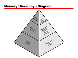
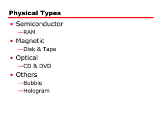
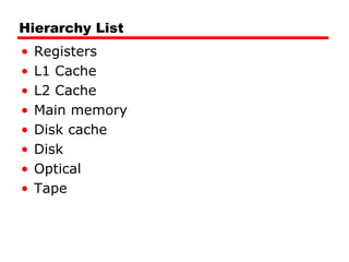
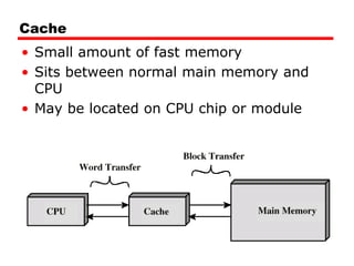
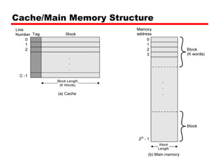
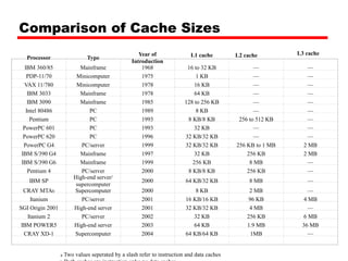
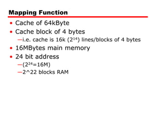
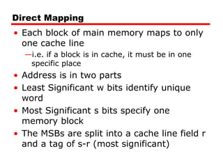
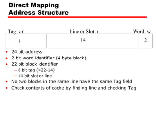
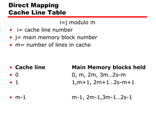
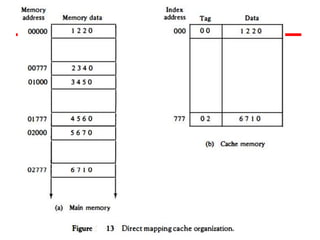
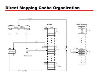
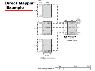
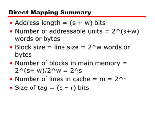
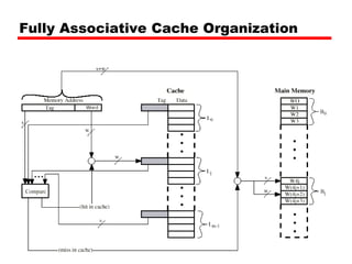
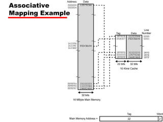
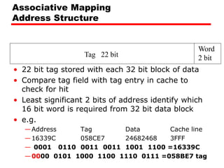
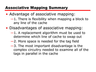
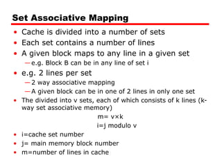
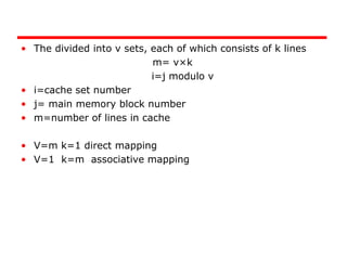
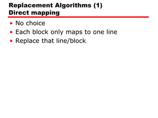
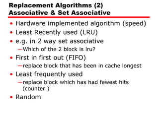
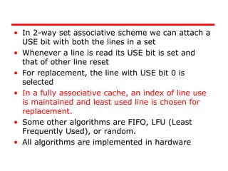
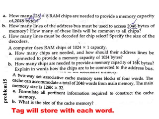
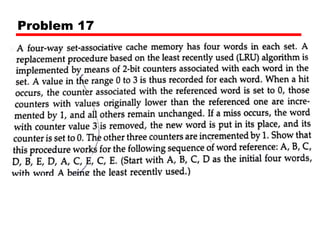
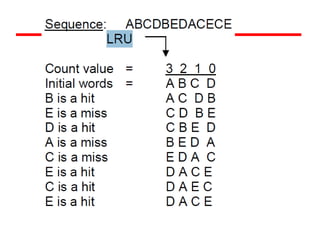
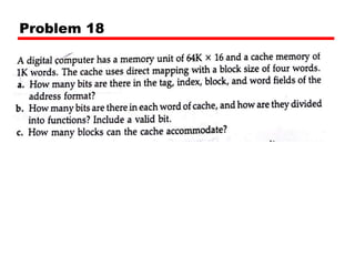
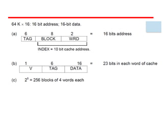
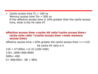
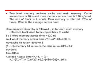
5. Unit of Transfer
• Internal
—Usually governed by data bus width
• External
—Usually a block which is much larger than a
word
• Addressable unit
—Smallest location which can be uniquely
addressed
—Word internally
—Cluster on M$ disks
6. Access Methods (1)
• Sequential
—Start at the beginning and read through in
order
—Access time depends on location of data and
previous location
—e.g. tape
• Direct
—Individual blocks have unique address
—Access is by jumping to vicinity plus
sequential search
—Access time depends on location and previous
location
—e.g. disk
7. Access Methods (2)
• Random
—Individual addresses identify locations exactly
—Access time is independent of location or
previous access
—e.g. RAM
• Associative
—Data is located by a comparison with contents
of a portion of the store
—Access time is independent of location or
previous access
—e.g. cache
8. Memory Hierarchy
• Registers
—In CPU
• Internal or Main memory
—May include one or more levels of cache
—“RAM”
• External memory
—Backing store
13. So you want fast?
• It is possible to build a computer which
uses only static RAM (see later)
• This would be very fast
• This would need no cache
—How can you cache cache?
• This would cost a very large amount
14. Locality of Reference
• During the course of the execution of a
program, memory references tend to
cluster
• e.g. loops
15. Cache
• Small amount of fast memory
• Sits between normal main memory and
CPU
• May be located on CPU chip or module
17. Cache operation – overview
• CPU requests contents of memory location
• Check cache for this data
• If present, get from cache (fast)
• If not present, read required block from
main memory to cache
• Then deliver from cache to CPU
• Cache includes tags to identify which
block of main memory is in each cache
slot
20. Cache Design
• Size
• Mapping Function
• Replacement Algorithm
• Write Policy
• Block Size
• Number of Caches
21. Comparison of Cache Sizes
a Two values seperated by a slash refer to instruction and data caches
Processor Type
Year of
Introduction
L1 cache L2 cache L3 cache
IBM 360/85 Mainframe 1968 16 to 32 KB — —
PDP-11/70 Minicomputer 1975 1 KB — —
VAX 11/780 Minicomputer 1978 16 KB — —
IBM 3033 Mainframe 1978 64 KB — —
IBM 3090 Mainframe 1985 128 to 256 KB — —
Intel 80486 PC 1989 8 KB — —
Pentium PC 1993 8 KB/8 KB 256 to 512 KB —
PowerPC 601 PC 1993 32 KB — —
PowerPC 620 PC 1996 32 KB/32 KB — —
PowerPC G4 PC/server 1999 32 KB/32 KB 256 KB to 1 MB 2 MB
IBM S/390 G4 Mainframe 1997 32 KB 256 KB 2 MB
IBM S/390 G6 Mainframe 1999 256 KB 8 MB —
Pentium 4 PC/server 2000 8 KB/8 KB 256 KB —
IBM SP
High-end server/
supercomputer
2000 64 KB/32 KB 8 MB —
CRAY MTAb Supercomputer 2000 8 KB 2 MB —
Itanium PC/server 2001 16 KB/16 KB 96 KB 4 MB
SGI Origin 2001 High-end server 2001 32 KB/32 KB 4 MB —
Itanium 2 PC/server 2002 32 KB 256 KB 6 MB
IBM POWER5 High-end server 2003 64 KB 1.9 MB 36 MB
CRAY XD-1 Supercomputer 2004 64 KB/64 KB 1MB —
22. Mapping Function
• Cache of 64kByte
• Cache block of 4 bytes
—i.e. cache is 16k (214) lines/blocks of 4 bytes
• 16MBytes main memory
• 24 bit address
—(224=16M)
—2^22 blocks RAM
23. Direct Mapping
• Each block of main memory maps to only
one cache line
—i.e. if a block is in cache, it must be in one
specific place
• Address is in two parts
• Least Significant w bits identify unique
word
• Most Significant s bits specify one
memory block
• The MSBs are split into a cache line field r
and a tag of s-r (most significant)
24. Direct Mapping
Address Structure
Tag s-r Line or Slot r Word w
8 14 2
• 24 bit address
• 2 bit word identifier (4 byte block)
• 22 bit block identifier
— 8 bit tag (=22-14)
— 14 bit slot or line
• No two blocks in the same line have the same Tag field
• Check contents of cache by finding line and checking Tag
25. Direct Mapping
Cache Line Table
i=j modulo m
• i= cache line number
• j= main memory block number
• m= number of lines in cache
• Cache line Main Memory blocks held
• 0 0, m, 2m, 3m…2s-m
• 1 1,m+1, 2m+1…2s-m+1
• m-1 m-1, 2m-1,3m-1…2s-1
29. Direct Mapping Summary
• Address length = (s + w) bits
• Number of addressable units = 2^(s+w)
words or bytes
• Block size = line size = 2^w words or
bytes
• Number of blocks in main memory =
2^(s+ w)/2^w = 2^s
• Number of lines in cache = m = 2^r
• Size of tag = (s – r) bits
30. Direct Mapping pros & cons
• Simple
• Inexpensive
• Fixed location for given block
—If a program accesses 2 blocks that map to
the same line repeatedly, cache misses are
very high
31. Associative Mapping
• A main memory block can load into any
line of cache
• Memory address is interpreted as tag and
word
• Tag uniquely identifies block of memory
• Every line’s tag is examined for a match
• Cache searching gets expensive
34. Tag 22 bit
Word
2 bit
Associative Mapping
Address Structure
• 22 bit tag stored with each 32 bit block of data
• Compare tag field with tag entry in cache to
check for hit
• Least significant 2 bits of address identify which
16 bit word is required from 32 bit data block
• e.g.
—Address Tag Data Cache line
—16339C 058CE7 24682468 3FFF
— 0001 0110 0011 0011 1001 1100 =16339C
—0000 0101 1000 1100 1110 0111 =058BE7 tag
35. Associative Mapping Summary
• Advantage of associative mapping:
—1. There is flexibility when mapping a block to
any line of the cache
• Disadvantages of associative mapping:
—1. A replacement algorithm must be used to
determine which line of cache to swap out
—2. More space is needed for the tag field
—3. The most important disadvantage is the
complex circuitry needed to examine all of the
tags in parallel in the cache
36. Set Associative Mapping
• Cache is divided into a number of sets
• Each set contains a number of lines
• A given block maps to any line in a given set
—e.g. Block B can be in any line of set i
• e.g. 2 lines per set
—2 way associative mapping
—A given block can be in one of 2 lines in only one set
• The divided into v sets, each of which consists of k lines (k-
way set associative memory)
m= v×k
i=j modulo v
• i=cache set number
• j= main memory block number
• m=number of lines in cache
37. Set Associative Mapping
Example
• 13 bit set number
• Block number in main memory is modulo
213
• 000000, 00A000, 00B000, 00C000 … map
to same set 0
39. Set Associative Mapping
Address Structure
• Use set field to determine cache set to
look in
• Compare tag field to see if we have a hit
• e.g
—Address Tag Data Set number
—1FF 7FFC 1FF 12345678 1FFF
—001 7FFC 001 11223344 1FFF
Tag 9 bit Set 13 bit
Word
2 bit
41. Set Associative Mapping Summary
• Address length = (s + w) bits
• Number of addressable units = 2^(s+w)
words or bytes
• Block size = line size = 2^w words or
bytes
• Number of blocks in main memory =
2^(s+w) / 2^w= 2^s
• Number of lines in set = k
• Number of sets = v = 2^d
• Number of lines in cache = kv = k * 2^d
• Size of tag = (s – d) bits
42. • The divided into v sets, each of which consists of k lines
m= v×k
i=j modulo v
• i=cache set number
• j= main memory block number
• m=number of lines in cache
• V=m k=1 direct mapping
• V=1 k=m associative mapping
44. Replacement Algorithms (2)
Associative & Set Associative
• Hardware implemented algorithm (speed)
• Least Recently used (LRU)
• e.g. in 2 way set associative
—Which of the 2 block is lru?
• First in first out (FIFO)
—replace block that has been in cache longest
• Least frequently used
—replace block which has had fewest hits
(counter )
• Random
45. • In 2-way set associative scheme we can attach a
USE bit with both the lines in a set
• Whenever a line is read its USE bit is set and
that of other line reset
• For replacement, the line with USE bit 0 is
selected
• In a fully associative cache, an index of line use
is maintained and least used line is chosen for
replacement.
• Some other algorithms are FIFO, LFU (Least
Frequently Used), or random.
• All algorithms are implemented in hardware
46. Write Policy
• Must not overwrite a cache block unless
main memory is up to date
• Multiple CPUs may have individual caches
• I/O may address main memory directly
47. Write through
• All writes go to main memory as well as
cache
• Multiple CPUs can monitor main memory
traffic to keep local (to CPU) cache up to
date
• Disadvantage
—Lots of traffic
—Slows down writes
48. Write back
• Updates initially made in cache only
• Update bit for cache slot/line is set when
update occurs
• If block is to be replaced, write to main
memory only if update bit is set
• Other caches get out of sync
• I/O must access main memory through
cache
55. • Cache access time Tc = 100 ns
Memory access time Tm = 500 ns
If the effective access time is 10% greater than the cache access
time, what is the hit ratio H?
effective access time =cache hit ratio*cache access time+
cache miss ratio *(cache access time +main memory
access time)
effective access time =10% greater the cache access time ==>110
let cache hit ratio is h
110 = h*100ns +(1-h) (100+500)
110= 100h+600-600h
500h= 490
h= 490/500= .98 = 98%
56. • Two level memory contains cache and main memory. Cache
access time is 20ns and main memory access time is 120ns/word.
The size of block is 4 words. Main memory is referred 20% of
times. What is the average access time:
Here memory hierarchy is followed , so for each main memory
reference block need to be copied back to cache
So 1 word memory access time =120 ns
so 4 word memory access time=Tm=4*120=480 ns
Hc=cache hit ratio= 80%=0.8
(1-Hc)=memory hit ratio=cache miss ratio=20%=0.2
Tc=20ns
Tm=480ns
Average Access time=Hc*TC + (1-
Hc)*(Tm+Tc)=(0.8*20)+0.2*(480+20)=116ns