Download to read offline

![Paulo Sérgio Martins Int. Journal of Engineering Research and Applications www.ijera.com
ISSN : 2248-9622, Vol. 4, Issue 9( Version 6), September 2014, pp.23-29
www.ijera.com 29 | P a g e
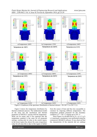
large deformations after the temperature variation, this is due to elastic deformation of the steel H13.
IV. CONCLUSIONS
Simulations using the finite element method helped in raising the temperature gradients, thermal conduction through the thermal chuck Concerning the behavior of AISI H13 before charging different temperature. It was observed that thermal fatigue is the physical phenomenon of magnitude higher among others. This phenomenon is not observed, because the number of temperature cycles was not sufficient to determine this deformation. Which may be represented by different thermal stresses during the process of assembly and disassembly of the thermal chuck tools. For future work simulation should be correlated with the physical part and thereby aiding in the creation of models of cooling and check mounting tensions between drill and chuck, predicting possible failures.
REFERENCES
[1.] ABAQUS/Standard User Manual, Version 6.10, 2011.
[2.] BEER, F.; JOHNSTON, R.; Resistência dos Materiais, 3. ed. São Paulo: Makron Books, 1995
[3.] CHIAVERINI, V. Aços e ferros fundidos. 4ª ed. São Paulo: Associação Brasileira de Metais, 1979, p. 19.
[4.] COSMOS/CAE, User’s Manual, Version 2011, 2011.
[5.] HARRIS, S.G.; VLASVED, A.C; DOYLE, E.D;DOLDER, P.J. Dry machining – commercial viability through filtered arc vapour deposited coating Surface and Coating Technology , n.133-134, pp 383-388, 2000.
[6.] Roberts, G., Krauss, G. and Kennedy, R. Tool Steels.ASM, 5th edition, EUA, p. 30-32 and 220-250, 1998.
[7.] DINIZ, A. E.; MARCONDES, F. C.; COPPINI, N. L., Tecnologia da Usinagem dos Materiais. 4. ed. São Paulo: Artliber, 2001.
[8.] KRESS, D. EL.,Escariadocon altas velocidades. Stuttgard, Tese de Doutorado - Universidad de Stuttgard, 1974.
[9.] KLOBCAR, D.; TUSEK, J.; Thermal Stresses in Aluminium Alloy Die Casting Dies, University of Ljubljana, Faculty of Mechanical Engineering, Laboratory for Welding, Askerceva, Slovenia, 2008.
[10.] MESQUITA, R. A., LEIVA, D. R., BARBOSA, C. A., “El Efecto de las Condicionesde Tratamiento Térmico
enlaMicroestructura y PropiedadesMecánicas de losAcerosHerramienta”. Pt1. Maquinas e Equipos: Herramientas e InsumosIndustriales, n547, Buenos Aires, Argentina, Set., 2006, p. 152-160.NADCA Recommended Procedures for H13 Tool Steel, EUA, 1997.
[11.] MEYERS, M. A.; CHAWLA, K. K.; Mechanical Behavior of Marerials, Prentice Hall : New Jersey cap. 14, 1999.
[12.] Padilha, Helio,: Desenvolvimento “IN SITU” de intermetálicos em superfícies de aço inoxidável, tese dourado, Universidade Federal do Paraná, 2002.
[13.] ROBERTS, G, KRAUSS, G., KENNEDY, R., “Tool Steels.” ASM, 5th edition, EUA,1988, p. 30-32 e 220-250.
[14.] ROBERTS, G., KRAUSS, G., KENNEDY, R., “Tool Steels.“ASM, 4th edition, EUA,1980, p. 393-395 e 563-585.
[15.] SCHULTZ, H.; MORIWAKI, T., High Speed Machining.Annals of the CIRP, v. 41, n.2, pp 637-643, 1993.
[16.] TRENT, E.M.; WRIGHT, P.K., Metal Cutting ,Butteworths-Heinemann. 4.ed. Ltd, London, 2000.
[17.] UGURAL, A. C.; FENSTER, S.K.; Advanced Strength and Applied Elasticity, The SI version. London, Elsevier Science Publishimg Co.,Inc., 1981.](https://image.slidesharecdn.com/c49062329-141021040812-conversion-gate02/85/Analysis-Of-The-Structure-Of-A-Material-Used-In-The-Manufacture-Of-Thermal-Chucks-For-Fixing-Tools-Cutting-Using-Finite-Elements-7-320.jpg)

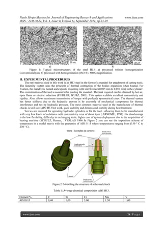
The study analyzes the elastic behavior of materials used in thermal chucks for cutting tools, particularly H13 steel, focusing on its thermal expansion and fatigue resistance during the assembly process. Various hard coatings were evaluated for their effectiveness in reducing thermal fatigue, with CRN and TiN coatings yielding the best results. The findings emphasize the importance of material characterization and proper handling of thermal stresses to enhance the performance and lifespan of cutting tools in machining processes.