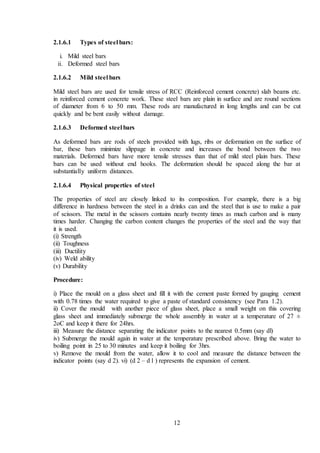
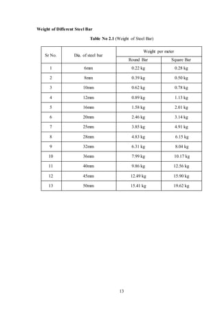
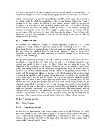
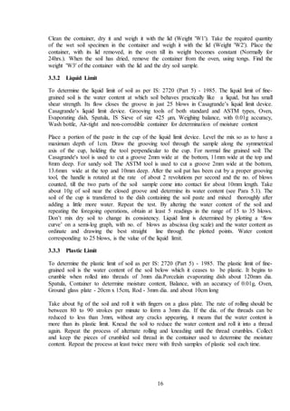
The document discusses various construction materials used in building projects including cement, sand, aggregate, bricks, blocks and steel. It provides details on the types and properties of these materials. Training and skills attained are also highlighted, covering various tests performed on aggregates, concrete, soil and cement, as well as methodology, loads, foundation work, tools used, and implementation and safety precautions.


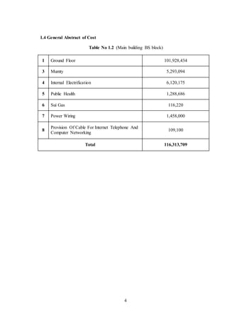
![5
Chapter 2- Training Work
2.1 Construction Materials
1.4.1 2.1.1 Cement
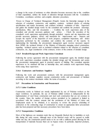
Cement is a cover material which makes a bond between aggregates and reinforcing materials.
Over the years. In the construction industry, there are different types of cement. The
differences between each type of cement are its properties, uses and composition materials
used during the manufacturing process.In the most general sense of the word, cement is a
binder, a substance that sets and hardens independently, and can bind other materials together.
The word "cement" traces to the Romans, who used the term opus caementicious to describe
masonry resembling modern concrete that was made from crushed rock with burnt lime as
binder. The volcanic ash and pulverized brick additives that were added to the burnt lime to
obtain a hydraulic binder were later referred to as cemented, cimentum, cement, and cement.
Cements used in construction can be characterized as being either hydraulic or non-hydraulic.
Hydraulic cements (e.g., Portland cement) harden because of hydration, a chemical reaction
between the anhydrous cement powder and water. Thus, they can harden underwater or when
constantly exposed to wet weather. The chemical reaction results in hydrates that are not very
water-soluble and so are quite durable in water. Non-hydraulic cements do not harden
underwater, slaked limes harden by reaction with atmospheric carbon dioxide. The most
important uses of cement are as an ingredient in the production of mortar in masonry, and of
concrete, a combination of cement and an aggregate to form a strong building material [1] .
Fig 2.1Port Land Cement
1.4.1.1 Physical properties
i. Fineness of cement
ii. Soundness
iii. Consistency](https://image.slidesharecdn.com/sajidreportfinal1-210630121246/85/Building-report-final-14-320.jpg)
![6
iv. Strength
v. Setting time
vi. Heat of hydration
vii. Loss of ignition
viii. Bulk density
ix. Specific gravity
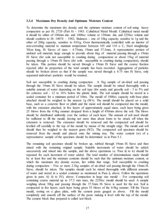
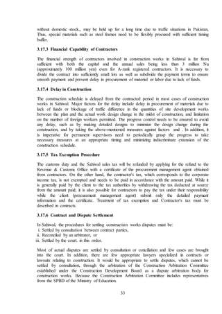
2.1.2.1 Port land cement
Cement manufactured from chalk and clay which hardens under water and when hard
resembles Portland stone in colour. Portland cement is the most common type of cement in
general use around the world as a basic ingredient of concrete, mortar, stucco, and non-
specialty grout. It was developed from other types of hydraulic lime in England in the early
19th century by Joseph Aspdin, and usually originates from limestone. It is a fine powder,
produced by heating limestone and clay minerals in a kiln to form clinker, grinding the clinker,
and adding 2 to 3 percent of gypsum. Several types of Portland cement are available. The most
common, called ordinary Portland cement (OPC), is grey, but white Portland cement is also
available. Its name is derived from its resemblance to Portland stone which was quarried on
the Isle of Portland in Dorset, England. It was named by Joseph Aspdin who obtained a patent
for it in 1824. However, his son William Aspdin is regarded as the inventor of "modern"
Portland cement due to his developments in the 1840s[2].
2.1.2 Sand
Sand is a granular material composed of finely divided rock and mineral particles. It is defined
by size, being finer than gravel and coarser than silt. Sand can also refer to a textural class of
soil or soil type i.e., a soil containing more than 85 percent sand-sized particles by mass. The
composition of sand is highly variable, depending on the local rock sources and conditions, but
the most common constituent of sand in inland continental settings and non-tropical coastal
settings is silica (silicon dioxide, or SiO2), usually in the form of quartz.
The second most common form of sand is calcium carbonate, for example aragonite, which has
mostly been created, over the past half billion years, by various forms of life, like coral and
shellfish. It is, for example, the primary form of sand apparent in areas where reefs have
dominated the ecosystem for millions of years like the Caribbean [3].
Fig 2.2 Ravi Sand](https://image.slidesharecdn.com/sajidreportfinal1-210630121246/85/Building-report-final-15-320.jpg)
![7
2.1.2.1 Composition
In terms of particle size as used by geologists, sand particles range in diameter from 0.0625
mm (or 1⁄16 mm) to 2 mm. An individual particle in this range size is termed a sand grain.
Sand grains are between gravel (with particles ranging from 2 mm up to 64 mm) and silt
(particles smaller than 0.0625 mm down to 0.004 mm). The size specification between sand
and gravel has remained constant for more than a century, but particle diameters as small as
0.02 mm were considered sand under the Albert Atterberg standard in use during the early 20th
century. A 1953 engineering standard published by the American Association of State
Highway and Transportation Officials set the minimum sand size at 0.074 mm. 1938
specification of the United States Department of Agriculture was 0.05 mm. Sand feels gritty
when rubbed between the fingers (silt, by comparison, feels like flour).
The most common constituent of sand, in inland continental settings and non-tropical coastal
settings, is silica (silicon dioxide, or SiO2), usually in the form of quartz, which, because of its
chemical inertness and considerable hardness, is the most common mineral resistant to
weathering[4].
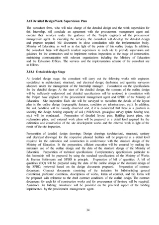
2.1.3 Aggregate
Construction aggregate are simply aggregate is a broad category of coarse Particulate material
used in construction including sand, gravel, crush, stone etc. Course aggregate; Coarse
aggregates are particles greater than 4.75mm, but generally range between 9.5mm to 37.5mm
in diameter. They can either be from Primary, Secondary or Recycled sources. Primary, or
'virgin', aggregates are either Land- or Marine-Won. Gravel is a coarse marine-won aggregate;
land-won coarse aggregates include gravel and crushed rock. Gravels constitute the majority
of coarse aggregate used in concrete with crushed stone making up most of the remainder.
Secondary aggregates are materials which are the byproducts of extractive operations and are
derived from a very wide range of materials.
Fig 2.3 Coarse Aggregate](https://image.slidesharecdn.com/sajidreportfinal1-210630121246/85/Building-report-final-16-320.jpg)
![8
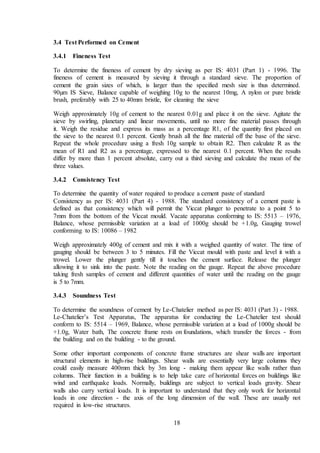
2.1.3.1 Coarse Aggregate
Coarse aggregates are larger size filler materials in construction. Coarse aggregates are the
particles that retain on 4.75 mm sieve. The surface area of coarse aggregate is less than fine
aggregates. Coarse aggregate acts as inert filler material for concrete. Coarse aggregates are
mainly used in concrete, railway track ballast, etc.
Fig 2.4 Coarse Aggregate
2.1.3.2 Fine aggregate
Fine aggregates are small size filler materials in construction. Fine aggregates are the particles
that pass through 4.75 mm sieve and retain on 0.075 mm sieve. The surface area of fine
aggregates is higher. The voids between the coarse aggregate are filled up by fine aggregate.
Fine aggregates are used in mortar, plaster, concrete, filling of road pavement layers, etc[5].
2.1.4 Bricks
Bricks are blocks of clay that have been hardened through being fired in a kiln or dried in the
sun. Over time, kiln-fired bricks have grown more popular than sun dried bricks, although both
are still found world widen the past, bricks came in many different shapes and sizes, but
today’s modern bricks tend to be a standard size or around 9'' × 4.5'' ×3''.](https://image.slidesharecdn.com/sajidreportfinal1-210630121246/85/Building-report-final-17-320.jpg)
![10
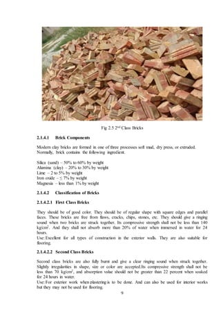
2.1.4.2.3 Third Class Bricks
These are not burnt so fully as in previous two cases but are generally of uniform reddish
yellow color. Its compressive strength lies between 35 – 70 kg/cm2 and absorption between 22
– 25 percent.
Use: They are used mostly in the ordinary type of construction and in dry situations.
2.1.4.2.4 Fourth Class Bricks
These types of bricks are irregular in shape and dark in color which is due to over burning.
They are quite strong in compressive strength, generally above 150 kg/cm2 and low in porosity
and absorption.
Use: They are, however, very commonly used in a broken form, in road construction,
foundations and floors as a coarse aggregate material[6].
2.1.4.3 Advantages of Bricks
i.The use of material such as bricks can increase the thermal mass of a building.
ii.Most types of masonry typically will not require painting and so can provide a structure with
reduced life-cycle costs.
iii.Masonry is very heat resistant and thus provides good fire protection.
iv.Masonry walls are more resistant to internshipiles, such as debris from hurricanes or
tornadoes.
v.Masonry structures built in compression preferably with lime mortar can have a useful life of
more than 500 years as compared to 30 to 100 for structures of steel or reinforced concrete.
2.1.4.4 Disadvantages of Bricks
i. Extreme weather causes degradation of masonry wall surfaces due to frost damage.
ii. This type of damage is common with certain types of brick, though rare with concrete.
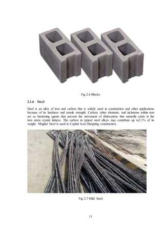
2.1.5 Blocks
i. Masonry tends to be heavy and must be built upon a strong foundation, such as reinforced
concrete, to avoid settling and cracking.
ii. Save for concrete, masonry construction does not lend itself well to mechanization, and
requires more skilled labor than stick-framing.](https://image.slidesharecdn.com/sajidreportfinal1-210630121246/85/Building-report-final-19-320.jpg)
![14
Chapter 3 - Skill Attained
3.1 Test Performed on Aggregates
3.1.1 Sieve Analysis Test
To determine the particle size distribution of fine and coarse aggregates by sieving as per IS:
2386 (Part I) - 1963.By passing the sample downward through a series of standard sieves, each
of decreasing size openings, the aggregates are separated into several groups, each of which
contains aggregates in a particular size range. A set of IS Sieves of sizes - 80mm, 63mm,
50mm, 40mm, 31.5mm, 25mm, 20mm, 16mm, 12.5mm, 10mm, 6.3mm, 4.75mm, 3.35mm,
2.36mm, 1.18mm, 600µm, 300µm, 150µm and 75µm . Balance or scale with an accuracy to
measure 0.1 percent of the weight of the test sample.
The test sample is dried to a constant weight at a temperature of 110+5 o C and weighed. The
sample is sieved by using a set of IS Sieves. On completion of sieving, the material on each
sieve is weighed. Cumulative weight passing through each sieve is calculated as a percentage
of the total sample weight. Fineness modulus is obtained by adding cumulative percentage of
aggregates retained on each sieve and dividing the sum by 100 [7].
3.1.2 Water Absorption Test
To determine the water absorption of coarse aggregates as per IS: 2386 (Part III) - 1963.Wire
basket - perforated, electroplated or plastic coated with wire hangers for suspending it from the
balance. Water-tight container for suspending the basket. Dry soft absorbent cloth - 75cm x
45cm (2 nos.).Shallow tray of minimum 650 sq.cm area. Air-tight container of a capacity
similar to the basket. Oven. A sample not less than 2000g should be used.
The sample should be thoroughly washed to remove finer particles and dust, drained and then
placed in the wire basket and immersed in distilled water at a temperature between 22 and 32
o C. After immersion, the entrapped air should be removed by lifting the basket and allowing it
to drop 25 times in 25 seconds. The basket and sample should remain immersed for a period of
24 + ½ hrs. afterwards. The basket and aggregates should then be removed from the water,
allowed to drain for a few minutes, after which the aggregates should be gently emptied from
the basket on to one of the dry clothes and gently surface-dried with the cloth, transferring it to
a second dry cloth when the first would remove no further moisture. The aggregates should be
spread on the second cloth and exposed to the atmosphere away from direct sunlight till it
appears to be completely surface-dry. The aggregates should be weighed (Weight 'A'). The
aggregates should then be placed in an oven at a temperature of 100 to 110 o C for 24hrs. It
should then be removed from the oven, cooled and weighed (Weight 'B').
3.2 Test Performed on Concrete
3.2.1 Rebound Hammer Test
To assess the likely compressive strength of concrete by using rebound hammer as per IS:
13311 (Part 2) - 1992. The rebound of an elastic mass depends on the hardness of the surface
against which its mass strikes. When the plunger of the rebound hammer is pressed against the
surface of the concrete, the spring-controlled mass rebounds and the extent of such a rebound
depends upon the surface hardness of the concrete. The surface hardness and therefore the
rebound is taken to be related to the compressive strength of the concrete. The rebound value is](https://image.slidesharecdn.com/sajidreportfinal1-210630121246/85/Building-report-final-23-320.jpg)
![23
Fig 3.4 Foundation (Pic 2)
3.7.3.1 Types of foundation
Foundation of building as the name implies is the starting of a building construction on site
really. Types of building, nature of soil and environmental conditions are the major
determinant of type of foundation you will use for your building.[8].
i. Strip foundation
ii. Pad foundation
iii. Raft foundation
iv. Pile foundation
3.7.3.1.1 Strip foundation
This is the most common type, it is mainly used where you have strong soil base and non-
waterlogged areas. Most small buildings of just a floor are constructed with this type of
foundation. Depends on the structural engineers recommendation, the depth of your foundation
could be from 600mm to 1200mm mostly for small scale buildings. When the soil is
excavated, a level at which the concrete will settle evenly is established, then concrete is
poured this may be from 150mm(6”) thick to 450mm(18”) thick depending also on building
after that block is set round the trenches at the center of foundation ,the foundation usually
follows the block lines. The blocks are then laid to D.P.C level before another concrete is
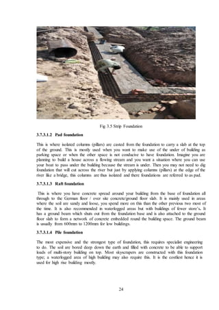
poured on top, this is the German or over site concrete. This type seems to be the cheapest.](https://image.slidesharecdn.com/sajidreportfinal1-210630121246/85/Building-report-final-32-320.jpg)
![25
3.8 Back Fill
To refill an excavation unit to restore the former ground surface and or to preserve the unit and
make it recognizable as have been excavated.
Fig 3.6 Back Fill (Pic 1)
Fig 3.7 Back Fill (Pic 2)
3.9 Water Stopper
Water Stops are flexible Plastic strips which provide a physical barrier to Water at concrete
joints, mostly in basements, Water retaining structures like Water tanks, Swimming pools,
structural foundations & other below ground level constructions. Water stops are also termed
as Water Bars, seals construction joints[9].](https://image.slidesharecdn.com/sajidreportfinal1-210630121246/85/Building-report-final-34-320.jpg)
![26
3.10Waterproofing
Waterproofing protects structures against water infiltration which can cause expensive and
irreversible damage. Waterproofing is the process of making an object or structure waterproof
or water-resistant so that it remains relatively unaffected by water or resisting the ingress of
water under specified conditions. Such items may be used in wet environments or underwater
to specified depths.
Water resistant and waterproof often refer to penetration of water in its liquid state and
possibly under pressure, whereas damp proof refers to resistance to humidity or dampness.
Permeation of water vapor through a material or structure is reported as a moisture vapor [10].
3.11Pile Foundation
Pile is a slender member with small area of cross-section relative to its length. They can
transfer load either by friction or by bearing. Pile foundation are used when:
i.The load is to be transferred to stronger or less compressible stratum, preferably rock.
ii.The granular soils need to be compacted.
iii.The horizontal and the inclined forces need to be carried from the bridge abutments and
the retaining walls[11].
3.11.1 Classification of Pile Foundation
The pile foundation can be further classified into following types on various basis such as
function, material, and method of installation which are listed below.
3.11.1.1 Basedon Function
i.Bearing piles
ii.Friction piles
iii.Combined piles (Both bearing and friction)
3.11.1.2 Basedon Material
i.Timber piles
ii.Concrete piles
iii.Steel piles
3.11.1.3 Basedon Method of Installation
i.Large displacement piles
ii.Small displacement piles
iii.Non-displacement piles
3.12Walls in concrete frame buildings
Concrete frame structures are strong and economical. Hence almost any walling materials can
be used with them. The heavier options include masonry walls of brick, concrete block, or
stone. The lighter options include drywall partitions made of light steel or wood studs covered
with sheeting boards. The former are used when strong, secure, and sound-proof enclosures are
required, and the latter when quick, flexible lightweight partitions are needed.](https://image.slidesharecdn.com/sajidreportfinal1-210630121246/85/Building-report-final-35-320.jpg)
![28
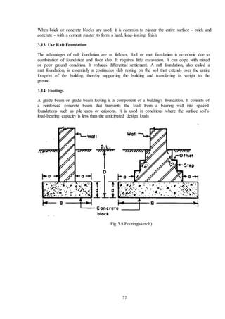
Fig 3.9 Footing (Pic)
3.14.1 Benefits of Footing Foundation
i.They provide a level surface upon which to build the foundation.
ii.Also, they provide resistance to the upward-acting forces of the soil opposing the
downward-acting forces of the weight above.
iii.With widths greater than the foundation itself, footings serve to distribute the building load
to the soil.
iv.Footings add strength to the foundation system in weak or expanding soils. Shifting soils
push on foundation walls above the footing and laterally.
v.Footings can help absorb the pressure and shore up the foundation against unstable earth.
vi.Footings allow the foundation to be sunk far enough below grade to avoid frost depths where
heaving and thawing also cause uneven settlement.
In summary, footings help prevent foundations from sinking or buckling. They also help the
foundation remain perpendicular to the ground, and keep tall buildings upright. Of the many
possibilities for footings, reinforced concrete can underpin the foundation in two styles[12].
3.15 Tools & Plants
The tools that construction workers use
3.15.1 Safety Equipment
According to the Bureau of Labor Statistics.
3.15.2 Hand Tools
For simple jobs, construction workers will use hand tools such as a hammer.](https://image.slidesharecdn.com/sajidreportfinal1-210630121246/85/Building-report-final-37-320.jpg)
![29
3.15.3 Trucks
To carry equipment and supplies from one place to another.
3.15.4 Air Compressor
A two-stage air compressor is often used at job sites for pneumatic tool
3.15.5 Compactor
Compactor is used to compact soft soil. It consist on simple vibrator and small petrol engine.
The function is vibrator to reduce air from soft soil for batter load bearing.
Fig 3.10 Compactor
3.15.6 Excavator
Excavators are heavy construction equipment consisting of a boom, dipper, bucket and cab on
a rotating platform known as the "house". The house sits atop an undercarriage with tracks or
wheels. They are a natural progression from the steam shovels and often mistakenly called
power shovels. All movement and functions of a hydraulic excavator are accomplished
through the use of hydraulic fluid, with hydraulic cylinders and hydraulic motors. Due to the
linear actuation of hydraulic cylinders, their[13].](https://image.slidesharecdn.com/sajidreportfinal1-210630121246/85/Building-report-final-38-320.jpg)
![30
Fig 3.11 Excavator
3.15.7 Concrete Mixer
A concrete mixer is a device that homogeneously combines cement, aggregate such as sand or
gravel, and water to form concrete. A typical concrete mixer uses a revolving drum to mix the
components. For smaller volume works, portable concrete mixers are often used so that the
concrete can be made at the construction site, giving the workers ample time to use the
concrete before it hardens. An alternative to a machine is mixing concrete by hand[14].
Fig 3.12 Concrete Mixer (Pic 1)](https://image.slidesharecdn.com/sajidreportfinal1-210630121246/85/Building-report-final-39-320.jpg)

![36
technical work, data collection/analysis and technical documents preparation processes.The
training is an important course because it closes the gap between the scientific study and
practical study. Learning you how to deal with other. Finding that team work is the most
important element in every successful project. Learned you that the civil engineer is capable of
a lot of work such as supervision, implementation, the calculation of quantities and design
engineering apprentice engineer and in the future can work as a consultant and contractor.
Learning you how to control & manage the site and how behaves when their problems by take
a professional decision. Plans must be clear and easy to read for those who used. Successful
engineer will find the economic design and the project is implemented less time. The site
engineer responsibility to make sure that everything is right on schedule and every member is
doing on the right way.
4.3 Recommendation
Most works in the site needs careful attention and successive supervision of works but the in
some case the site works goes improperly due to different causes. This kind of carelessness is
not good for ether the consultant or the contractor. Therefore I suggest supervisors and site
engineers to take a care full look after the work executed on the site and the work that will be
executed. In the site there are works which is performed in the way that not to be performed.
Such works lids to safety problem, loose of human power if its degree is high and economy if it
is ordered to demolish it. Thus I recommend for the company the following. 1st of all level all
the constructed area according to the drawing level. Testing of material before it delivered to
the site and after it delivered and also when it is in use for construction. It is better to use steel
form work than wood (plywood) formwork as it is very repetitively used, stiff, and not
flammable easily and removed easily without damaging the concrete structure. A cover
material could be used for curing for any casted concrete structure until it attains its strength.
References
[1]Rodgers, Lucy (17 December 2018). "The massive CO2 emitter you may not know
about". BBC News. Retrieved 17 December 2018.
(6:30 pm , 03-06-20)
[2]ourland, Robert (2011). Concrete planet : the strange and fascinating story of the world's
most common man-made material. Amherst, N.Y.: Prometheus Books. ISBN 978-1616144814.
Retrieved 28 August 2015.
(8:30 am , 08-06-20)
[3] Glossary of terms in soil science (PDF). Ottawa: Agriculture Canada. 1976.
p. 35. ISBN 978-0662015338.
(5:30 pm , 15-06-20)
[4]Urquhart, Leonard Church, "Civil Engineering Handbook" McGraw-Hill Book Company
(1959)
(2:30 pm , 22-06-20)
[5]https://civiltoday.com/civil-engineering-materials/aggregate/253-difference-between-fine-
and-coarse-aggregate
(10:40 am , 28-06-20)
[6]https://civilseek.com/types-classification-ofbricks/#:~:text=Building%20bricks%20may%20
be%20defined ,molding%2C%20drying%20and%20burning.%E2%80%9D](https://image.slidesharecdn.com/sajidreportfinal1-210630121246/85/Building-report-final-45-320.jpg)
![37
(8:25 pm , 04-07-20)
[7]PavementInteractive. GradationTest.(2007). http://pavementinteractive.org/index.php?title=
Gradation_Test
(9:55 pm , 12-07-20)
[8] Pakistan Environmental Protection Agency, Brick Kiln Units (PDF file) Archived 16 June
2007 at the Wayback Machine
(6:45 pm , 19-07-20)
[9]engineeringcivil.com/what-is-the-function-of-waterstops-in-joints-of-box-culverts-and-
drainage-channels.
11:30 am , 22-07-20)
[10]U.S. Department of Energy/Brookhaven National Laboratory (October 21, 2013). "Nano-
cone textures generate extremely 'robust' water-repellent surfaces". Science Daily.
Retrieved October 22, 2013
(12:45 pm , 29-07-20)
[11] Designing Buildings https://www.designingbuildings.co.uk/wiki/Substructure
(6:30 pm , 03-08-20)
[12] Weygandt; Kieso; Kimmel (2003). Financial Accounting. Susan Elbe. p. 6. ISBN 0-471-
07241-9.
(9:12 pm , 09-08-20)
[13]Compact Excavator Specifications and Comparisons
(7:35 pm , 12-08-20)
[14] Hunker, Henry L. (2000). Columbus, Ohio: A Personal Geography. Ohio State University
Press. pp. 196. ISBN 978-0-8142-0857-1.
(11:55 am , 15-08-20)
[15]Glick, Thomas F. Livesey, Steven John & Wallis, Faith (2005). Medieval Science,
Technology, and Medicine: An Encyclopedia. Routledge. ISBN 0415969301.
(1:30 pm , 18-08-20)
[16]Terzaghi, Karl; Peck, Ralph Brazelton; Mesri, Gholamreza (1996), Soil mechanics in
engineering practice (3rd ed.), New York: John Wiley & Sons, p. 386, ISBN 0-471-08658-4
(9:00 pm , 25-08-20)](https://image.slidesharecdn.com/sajidreportfinal1-210630121246/85/Building-report-final-46-320.jpg)