Download as PDF, PPTX
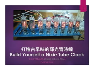
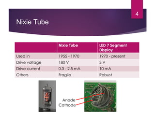
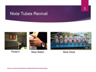
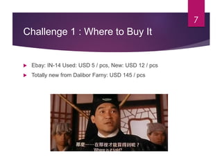
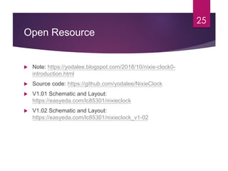

This document is a presentation by 李祐棠 on building a nixie tube clock, highlighting challenges related to sourcing components, high voltage circuits, and custom PCB design. It details solutions for controlling the nixie tubes including recommended ICs, microcontrollers, and PCB design tools. The presentation also provides links to resources for further information and open-source code related to the project.