Download to read offline


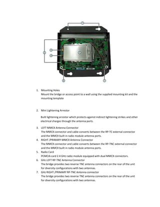


The document describes the ports and connectors on a wireless bridge device, including: - Two reverse RP-TNC antenna connectors for connecting external antennas or for diversity configurations with two antennas. - A serial console port for connecting to a computer COM port using a serial cable. - An Ethernet port for 10/100 Mbps connection. - Mounting holes for wall mounting with a supplied kit.


