This document provides an owner's manual for the RCI-2950DX/2970DX-150 10 and 12 meter dual band amateur radio. It includes specifications for the radio, instructions for unpacking, installing, and operating the radio. The operating section describes the front and rear panels and how to use the controls like frequency selection, mode selection, scanning functions, and programming memories. It also covers programming features like receive scanning, split operation, and memory functions.
Mitsubishi ac servos melservo j3-dienhathe.vnDien Ha The
Khoa Học - Kỹ Thuật & Giải Trí: http://phongvan.org
Tài Liệu Khoa Học Kỹ Thuật: http://tailieukythuat.info
Thiết bị Điện Công Nghiệp - Điện Hạ Thế: http://dienhathe.org
Mitsubishi ac servos melservo j3-dienhathe.vnDien Ha The
Khoa Học - Kỹ Thuật & Giải Trí: http://phongvan.org
Tài Liệu Khoa Học Kỹ Thuật: http://tailieukythuat.info
Thiết bị Điện Công Nghiệp - Điện Hạ Thế: http://dienhathe.org
When it comes to high performance signal chains, you need high performance power solutions. Noise sensitive
circuits such as analog-to-digital converters (ADCs), digital-to-analog converters (DACs), amplifiers, and phase
lock loops (PLLs)—as well as FPGAs—demand low noise power supplies that require specialized design
techniques. Engineers spend hours trying to figure out how to power these circuits without adding noise.
This presentation will focus on understanding various methods for not only approaching but meeting system
requirements. The session will introduce tested solutions and layout considerations that must be taken into
account when designing with switching regulators and low drop out (LDO) regulators.
For more than fifty years, Dukane’s Audio Visual Products Division has provided schools and businesses around the world with technology solutions that helped increase learning. With a network of trained professional dealers available to provide personal and localized sales support, Dukane is committed to meeting each customer’s particular needs.
For more information contact:
Delia Valdez
Dukane Customer Service Representative
Phone: 888-245-1966
Fax: (630) 584-5156
Emai; avsales@dukane.com
Website: www.Dukane.com/AV
For information on Dukane’s Innovative Convey Response system, go to
www.conveyclassrooms.com
Dukane AV
2900 Dukane Drive
St. Charles, IL 60174
PORTABLE WIRELESS AMPLIFIER BLUETOOTH - 5 CoreSonuKumar969
5CORE® 5C WPA 116 BDH Portable Wireless Amplifier delivering great sound output enhancing user’s experience due to its dynamic features, fine appearance, and wireless applications.
DevOps and Testing slides at DASA ConnectKari Kakkonen
My and Rik Marselis slides at 30.5.2024 DASA Connect conference. We discuss about what is testing, then what is agile testing and finally what is Testing in DevOps. Finally we had lovely workshop with the participants trying to find out different ways to think about quality and testing in different parts of the DevOps infinity loop.
Neuro-symbolic is not enough, we need neuro-*semantic*Frank van Harmelen
Neuro-symbolic (NeSy) AI is on the rise. However, simply machine learning on just any symbolic structure is not sufficient to really harvest the gains of NeSy. These will only be gained when the symbolic structures have an actual semantics. I give an operational definition of semantics as “predictable inference”.
All of this illustrated with link prediction over knowledge graphs, but the argument is general.
LF Energy Webinar: Electrical Grid Modelling and Simulation Through PowSyBl -...DanBrown980551
Do you want to learn how to model and simulate an electrical network from scratch in under an hour?
Then welcome to this PowSyBl workshop, hosted by Rte, the French Transmission System Operator (TSO)!
During the webinar, you will discover the PowSyBl ecosystem as well as handle and study an electrical network through an interactive Python notebook.
PowSyBl is an open source project hosted by LF Energy, which offers a comprehensive set of features for electrical grid modelling and simulation. Among other advanced features, PowSyBl provides:
- A fully editable and extendable library for grid component modelling;
- Visualization tools to display your network;
- Grid simulation tools, such as power flows, security analyses (with or without remedial actions) and sensitivity analyses;
The framework is mostly written in Java, with a Python binding so that Python developers can access PowSyBl functionalities as well.
What you will learn during the webinar:
- For beginners: discover PowSyBl's functionalities through a quick general presentation and the notebook, without needing any expert coding skills;
- For advanced developers: master the skills to efficiently apply PowSyBl functionalities to your real-world scenarios.
State of ICS and IoT Cyber Threat Landscape Report 2024 previewPrayukth K V
The IoT and OT threat landscape report has been prepared by the Threat Research Team at Sectrio using data from Sectrio, cyber threat intelligence farming facilities spread across over 85 cities around the world. In addition, Sectrio also runs AI-based advanced threat and payload engagement facilities that serve as sinks to attract and engage sophisticated threat actors, and newer malware including new variants and latent threats that are at an earlier stage of development.
The latest edition of the OT/ICS and IoT security Threat Landscape Report 2024 also covers:
State of global ICS asset and network exposure
Sectoral targets and attacks as well as the cost of ransom
Global APT activity, AI usage, actor and tactic profiles, and implications
Rise in volumes of AI-powered cyberattacks
Major cyber events in 2024
Malware and malicious payload trends
Cyberattack types and targets
Vulnerability exploit attempts on CVEs
Attacks on counties – USA
Expansion of bot farms – how, where, and why
In-depth analysis of the cyber threat landscape across North America, South America, Europe, APAC, and the Middle East
Why are attacks on smart factories rising?
Cyber risk predictions
Axis of attacks – Europe
Systemic attacks in the Middle East
Download the full report from here:
https://sectrio.com/resources/ot-threat-landscape-reports/sectrio-releases-ot-ics-and-iot-security-threat-landscape-report-2024/
Essentials of Automations: Optimizing FME Workflows with ParametersSafe Software
Are you looking to streamline your workflows and boost your projects’ efficiency? Do you find yourself searching for ways to add flexibility and control over your FME workflows? If so, you’re in the right place.
Join us for an insightful dive into the world of FME parameters, a critical element in optimizing workflow efficiency. This webinar marks the beginning of our three-part “Essentials of Automation” series. This first webinar is designed to equip you with the knowledge and skills to utilize parameters effectively: enhancing the flexibility, maintainability, and user control of your FME projects.
Here’s what you’ll gain:
- Essentials of FME Parameters: Understand the pivotal role of parameters, including Reader/Writer, Transformer, User, and FME Flow categories. Discover how they are the key to unlocking automation and optimization within your workflows.
- Practical Applications in FME Form: Delve into key user parameter types including choice, connections, and file URLs. Allow users to control how a workflow runs, making your workflows more reusable. Learn to import values and deliver the best user experience for your workflows while enhancing accuracy.
- Optimization Strategies in FME Flow: Explore the creation and strategic deployment of parameters in FME Flow, including the use of deployment and geometry parameters, to maximize workflow efficiency.
- Pro Tips for Success: Gain insights on parameterizing connections and leveraging new features like Conditional Visibility for clarity and simplicity.
We’ll wrap up with a glimpse into future webinars, followed by a Q&A session to address your specific questions surrounding this topic.
Don’t miss this opportunity to elevate your FME expertise and drive your projects to new heights of efficiency.
Generating a custom Ruby SDK for your web service or Rails API using Smithyg2nightmarescribd
Have you ever wanted a Ruby client API to communicate with your web service? Smithy is a protocol-agnostic language for defining services and SDKs. Smithy Ruby is an implementation of Smithy that generates a Ruby SDK using a Smithy model. In this talk, we will explore Smithy and Smithy Ruby to learn how to generate custom feature-rich SDKs that can communicate with any web service, such as a Rails JSON API.
Dev Dives: Train smarter, not harder – active learning and UiPath LLMs for do...UiPathCommunity
💥 Speed, accuracy, and scaling – discover the superpowers of GenAI in action with UiPath Document Understanding and Communications Mining™:
See how to accelerate model training and optimize model performance with active learning
Learn about the latest enhancements to out-of-the-box document processing – with little to no training required
Get an exclusive demo of the new family of UiPath LLMs – GenAI models specialized for processing different types of documents and messages
This is a hands-on session specifically designed for automation developers and AI enthusiasts seeking to enhance their knowledge in leveraging the latest intelligent document processing capabilities offered by UiPath.
Speakers:
👨🏫 Andras Palfi, Senior Product Manager, UiPath
👩🏫 Lenka Dulovicova, Product Program Manager, UiPath
Slack (or Teams) Automation for Bonterra Impact Management (fka Social Soluti...Jeffrey Haguewood
Sidekick Solutions uses Bonterra Impact Management (fka Social Solutions Apricot) and automation solutions to integrate data for business workflows.
We believe integration and automation are essential to user experience and the promise of efficient work through technology. Automation is the critical ingredient to realizing that full vision. We develop integration products and services for Bonterra Case Management software to support the deployment of automations for a variety of use cases.
This video focuses on the notifications, alerts, and approval requests using Slack for Bonterra Impact Management. The solutions covered in this webinar can also be deployed for Microsoft Teams.
Interested in deploying notification automations for Bonterra Impact Management? Contact us at sales@sidekicksolutionsllc.com to discuss next steps.
Connector Corner: Automate dynamic content and events by pushing a buttonDianaGray10
Here is something new! In our next Connector Corner webinar, we will demonstrate how you can use a single workflow to:
Create a campaign using Mailchimp with merge tags/fields
Send an interactive Slack channel message (using buttons)
Have the message received by managers and peers along with a test email for review
But there’s more:
In a second workflow supporting the same use case, you’ll see:
Your campaign sent to target colleagues for approval
If the “Approve” button is clicked, a Jira/Zendesk ticket is created for the marketing design team
But—if the “Reject” button is pushed, colleagues will be alerted via Slack message
Join us to learn more about this new, human-in-the-loop capability, brought to you by Integration Service connectors.
And...
Speakers:
Akshay Agnihotri, Product Manager
Charlie Greenberg, Host
Kubernetes & AI - Beauty and the Beast !?! @KCD Istanbul 2024Tobias Schneck
As AI technology is pushing into IT I was wondering myself, as an “infrastructure container kubernetes guy”, how get this fancy AI technology get managed from an infrastructure operational view? Is it possible to apply our lovely cloud native principals as well? What benefit’s both technologies could bring to each other?
Let me take this questions and provide you a short journey through existing deployment models and use cases for AI software. On practical examples, we discuss what cloud/on-premise strategy we may need for applying it to our own infrastructure to get it to work from an enterprise perspective. I want to give an overview about infrastructure requirements and technologies, what could be beneficial or limiting your AI use cases in an enterprise environment. An interactive Demo will give you some insides, what approaches I got already working for real.
Epistemic Interaction - tuning interfaces to provide information for AI supportAlan Dix
Paper presented at SYNERGY workshop at AVI 2024, Genoa, Italy. 3rd June 2024
https://alandix.com/academic/papers/synergy2024-epistemic/
As machine learning integrates deeper into human-computer interactions, the concept of epistemic interaction emerges, aiming to refine these interactions to enhance system adaptability. This approach encourages minor, intentional adjustments in user behaviour to enrich the data available for system learning. This paper introduces epistemic interaction within the context of human-system communication, illustrating how deliberate interaction design can improve system understanding and adaptation. Through concrete examples, we demonstrate the potential of epistemic interaction to significantly advance human-computer interaction by leveraging intuitive human communication strategies to inform system design and functionality, offering a novel pathway for enriching user-system engagements.
Smart TV Buyer Insights Survey 2024 by 91mobiles.pdf91mobiles
91mobiles recently conducted a Smart TV Buyer Insights Survey in which we asked over 3,000 respondents about the TV they own, aspects they look at on a new TV, and their TV buying preferences.
Transcript: Selling digital books in 2024: Insights from industry leaders - T...BookNet Canada
The publishing industry has been selling digital audiobooks and ebooks for over a decade and has found its groove. What’s changed? What has stayed the same? Where do we go from here? Join a group of leading sales peers from across the industry for a conversation about the lessons learned since the popularization of digital books, best practices, digital book supply chain management, and more.
Link to video recording: https://bnctechforum.ca/sessions/selling-digital-books-in-2024-insights-from-industry-leaders/
Presented by BookNet Canada on May 28, 2024, with support from the Department of Canadian Heritage.
Transcript: Selling digital books in 2024: Insights from industry leaders - T...
Rci2950 dx70 150-owners
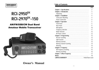
1. Table of Contents
PAGE
DX
RCI-2950
DX
RCI-2970 -150
AM/FM/SSB/CW Dual Band
Amateur Mobile Transceiver
Chapter 1 Specifications .......................................................
2
Chapter 2 Introduction ..........................................................
3
Unpacking ...........................................................................
3
Chapter 3 Installation ............................................................
4
Transceiver Mounting ...........................................................
4
Power Connection ...............................................................
4
Chapter 4 Operation ..............................................................
5
Front Panel ..........................................................................
5
Rear Panel ...........................................................................
9
Microphone .........................................................................
10
Frequency Selection .............................................................
11
Mode Selection ....................................................................
12
RF Power Control .................................................................
12
Chapter 5 Programming ........................................................
13
Receive Scanning ...............................................................
13
Split Function .......................................................................
13
Memory Function .................................................................
13
Memory Channel Scanning ...................................................
14
Metering ..............................................................................
14
Chapter 6 Frequency
14
S All-Frequency Scanning ........................................................
i
15
Memory Scanning ................................................................
16
Chapter 7 Offset Frequency
17
O
Memo i....................................................................................
18
LIMITED WARRANTY .............…............................. Inside Back Cover
Owner's Manual
-1-
2. Chapter 1 Specifications
Chapter 2 Introduction
GENERAL
Congratulations on your purchase of an RCI-2950DX/2970DX-150 10
and 12 meter dual band amateur radio. Your RCI-2950DX/2970DX-150 is
designed to provide trouble-free service and state-of-the-art
communications, incorporating many useful features and functions in the
10 and 12 meter dual band radio. Please read this manual thoroughly to
ensure proper performance.
Model
RCI-2950DX
RCI-2970DX-150
Frequency Range: 12 meter
: 10 meter
24.8900 ~24.9900 MHz
28.0000 ~29.6999 MHz
100 Hz, 1 KHz, 10 KHz,
100 KHz, 1 MHz
24.8900 ~24.9900 MHz
28.0000 ~29.6999 MHz
100 Hz, 1 KHz, 10 KHz,
100 KHz, 1 MHz
Emission
USB, LSB, CW, AM, FM
USB, LSB, CW, AM, FM
Frequency Control
Phase-Lock-Loop Synthesizer
Phase-Lock-Loop Synthesizer
Frequency Tolerance
0.005%
0.005%
IMPORTANT
0.001%
To operate this radio, you must possess and amateur radio operator's
license issued by the FCC. Operation of this unit without proper
licensing is ILLEGAL and can result in severe penalties.
Tuning Steps
Frequency Stability
0.001%
Operating Temperature
Range
-10 C to +50 C
-10OC to +50OC
Antenna Impedance
50 ohm
50 ohm
Microphone
Plug-In (6-Pin), 400 Ω Dynamic PTT
Plug-In (6-Pin), 400 Ω Dynamic PTT
Meter Function
RF Output, RX Receive Signal
Strength, SWR
RF Output, RX Receive Signal
Strength, SWR
Input Voltage
13.8 V DC
13.8 V DC
O
O
Dimensions
7 3/4" (W) x 10 3/4" (D) x 2 3/8" (H)
7 3/4" (W) x 9 3/4" (D) x 2 7/8" (H)
Weight
4 lb. 3 oz.
5 lb. 13 oz.
RF Power Output
25W : USB/LSB Peak Power
10W : CW/AM/FM
150W : USB/LSB Peak Power
50W : CW/AM/FM
RF Transmit Modes
USB, LSB, CW, AM, FM
USB, LSB, CW, AM, FM
Antenna Connector
UHF Type, 50 Ω
UHF Type, 50 Ω
Modulation
16F3, A3E, J3E, A1A
16F3, A3E, J3E, A1A
Spurious Emissions
>60 dB
>60 dB
Carrier Suppression
-50 dB
-50 dB
Sensitivity
AM/CW : 0.5 μV for 10dB Sinad
FM : 0.25μV for 12dB Sinad
USB/LSB : 0.15μV for 10dB Sinad
AM/CW : 0.5 μV for 10dB Sinad
FM : 0.25μV for 12dB Sinad
USB/LSB : 0.15μV for 10dB Sinad
Image Rejection Ratio
-65 dB
-65 dB
AGC Figure of Merit
SSB/CW/AM : 80dB at 50mV for a
10dB change in Audio Output
SSB/CW/AM : 80dB at 50mV for a
10dB change in Audio Output
Audio Power Output
2.5W
2.5W
TRANSMITTER
RECEIVER
( SPECIFICATIONS SUBJECT TO CHANGE WITHOUT NOTICE )
-2-
NOTE
The manufacturer is not responsible for any radio or TV interference
caused by unauthorized modifications to this equipment. Such
modifications could void the user’s authority to operate this equipment.
Unpacking
The following items are included with our RCI-2950DX/2970DX-150.
Carefully remove and examine all materials from the packing carton. If
any items are missing or appear damaged, please contact your dealer
immediately. Each unit should include:
(1) RCI-2950DX/2970DX-150 Transceiver
(2) Dynamic Microphone with remote frequency adjustment switches
(3) Power Cord
(4) Mounting Bracket & Hardware
(5) Installation Hardware
(6) Owner's Manual
(7) Warranty Registration Card
It is recommended that you save the packing materials for future storage
or shipping.
-3-
3. Chapter 3 Installation
Chapter 4 Operation
The RCI-2950DX/2970DX-150 is easy to install. All necessary parts (less
the antenna and coax cable) have been included to facilitate installation.
Front Panel
Transceiver Mounting
Choose a suitable location for the transceiver that will allow easy access
to the front panel as well as proper air circulation to the back of the unit.
If you are installing the unit in a vehicle, attach the mounting bracket first,
then attach the transceiver to the mounting bracket using the hardware
provided. Before making any electrical connection, ensure that the
transceiver is turned off and the vehicle's battery is disconnected.
Power Connection
The transceiver operates off of any 12 to 13.8 VDC source. Beware of
voltage drops caused by operating from Cigarette Lighter Plugs or long
DC wire runs. Sometimes it is best to connect direct to the battery for
best RF output and Tx audio quality
NOTE
The condition of a vehicle's electrical system can affect the operation of
your RCI-2950DX/2970DX-150. A low battery, worn generator/
alternator, or poor voltage regulator will impair performance of the unit
as well as the vehicle.
If an AC power supply is used with your radio, it must be regulated and
rated for at least 7 Amps continuous for the RCI-2950DX and 20 Amps
continuous for the RCI-2970DX-150. Low voltage while under load will
cause reduced receiver gain and low transmitter output with possible
distortion and splatter.
CAUTION
Voltage above 15 VDC will damage the unit. Be sure to check the
source voltage before connecting the power cord.
-4-
1. FREQUENCY SELECTOR: Used to set the desired transmit and receive
frequency. The frequency is digitally displayed in the LCD window next
to the selector. The FREQUENCY SELECTOR knob next to the LCD
display, allows changing each digit on the frequency display by first
placing the frequency display cursor (using SHF button) below the
desired digit and then turning the selector knob.
2. RF POWER CONTROL: This control adjust the Transmitter’s RF power
output level.
3. MIC GAIN CONTROL: This feature adjust the microphone gain for the
transmit and PA modes. Experiment with this control for the setting that
will provide best audio quality. Avoid over-modulation, which causes
interference to adjacent stations and “splatter”.
4. ON/OFF VOLUME CONTROL: Turn clockwise to apply power to the
radio and to set the desired listening level.
-5-
4. Operation (Continued)
Operation (Continued)
5. SQUELCH CONTROL: This control is used to control or eliminate
receiver background noise in the absence of an incoming signal. For
maximum receiver sensitivity, it is necessary that the control be
adjusted only to the point where the receiver background noise is
eliminated. Turn fully counterclockwise and then slowly clockwise until
the receiver noise just disappears. Any signal to be received must now
be slightly stronger than the average received noise. Further clockwise
rotation will increase the threshold level that a signal must overcome in
order to be heard. Only strong signals will be heard at a maximum
clockwise squelch setting.
6. RF GAIN CONTROL: This control is used to reduce the receiver's frontend gain when receiving strong signals.
be having trouble receiving will know that you have finished
transmitting. This feature is sometimes used in weak signal conditions
or other special circumstances. We discourage use of this feature in
normal operation, as it can be annoying to other operators.
11. SPLIT BUTTON (SPLIT): Enables the offsetting of the transmitter
frequency by up to ± 2 MHz (programmable) for FM repeater
operation.
12. PROGRAM BUTTON (PRG): Used to pre-program operating or
scanning frequencies into memory. See the OPERATION section of this
manual for details.
13. MANUAL BUTTON (MAN): Used to return the unit to manual mode.
7. CLARIFIER CONTROL: Allows variation of the receive frequency above
and below the selected receive frequency as shown on the display.
This control is intended primarily to tune in SSB signals when
communicating with several stations that may not be exactly on
frequency. It may also be used to optimize AM/FM signals as
described in the operating procedure paragraph. The clarifier can adjust
the receive frequency ±2.5KHz but does not affect the transmit
frequency or the frequency display.
14. SHIFT BUTTON (SHF): Determines which digit will change when
changing frequencies, by placing a “cursor” under the desired digit.
Allows frequency to be changed in 100 Hz, 1KHz, 10KHz, 100KHz and
1 MHz increments.
8. MODE SWITCH: This switch allows you to select one of the following
six operating modes: FM, AM, USB, LSB, CW and PA.
17. SCAN BUTTON (SCAN): Used to enable the scanning of frequencies.
See the PROGRAMMING and SCANNING section of this manual for
detailed information on using the scan control.
9. NB/ANL BUTTON (NB/ANL): The noise blanker (NB) is very effective in
eliminating repetitive impulse noise such as ignition interference. In the
ANL position, the AUTOMATIC NOISE LIMITER also limits noise at the
receiver audio stages.
10. ROGER BEEP BUTTON (R.BEEP): This switch activates the ROGER
BEEP circuit, when its function is selected. When enabled, the radio
automatically transmits an audio tone each time you release the PTT.
This indicates the end of each transmission so that stations who may
-6-
15. DIM BUTTON (DIM): This button adjusts the display backlighting in
four different steps to best match the ambient light.
16. SWR BUTTON (SWR): Used to check relative SWR.
18. MEMORY BUTTON (MEM): Used to program often used frequencies
in memory. Detailed information on how to use this control is provided
in the PROGRAMMING section of the manual.
19. ENTER BUTTON (ENT): Used to program frequencies in memory.
See PROGRAMMING section.
-7-
5. Operation (Continued)
Operation (Continued)
20. LOCK BUTTON (LOCK): Disables the Frequency Selector Control,
UP/DOWN buttons on the front control panel and remote UP/DOWN
buttons on the microphone. Pressing this switch again will re-enable
the frequency selectors.
Rear Panel
1
2
3
4
21. UP/DOWN SELECTOR: These buttons are used to increase or
decrease the frequency digit above the SHF cursor on the display.
5
1. ANTENNA: This jack accepts a 50 ohms coaxial cable with a PL-259
style plug.
2. CW KEY: The CW key is used for Morse Code operation. To operate
connect a CW key to this jack, and place the mode switch in the CW
position.
3. EXTERNAL SPEAKER: This jack accepts a 4 - 8 ohm 5W external
speaker. When an external speaker is connected to this jack, the builtin speaker is disabled.
4. PA SP.: An 8 ohm, 4W PA speaker may be connected to this jack for
PA operation. This feature operates by placing mode selector in PA
position.
5. POWER: This socket accepts a 13.8 VDC power cable with built-in
fuse. The power cord provided with the radio consists of a black wire
(negative) and a red wire (positive ).
-8-
-9-
6. Operation (Continued)
Operation (Continued)
Microphone
Frequency Selection
1. PTT SWITCH: The Push-To-Talk (PTT) switch controls the transmit
and receive function of the radio. Push to transmit and release to
receive.
2. REMOTE UP/DOWN SWITCH: The digit on the frequency display
above the SHF “cursor” can be stepped up or down by pushing either
of these buttons.
For best results, the user should select a low-impedance dynamic type
microphone or a transistorized microphone.
The microphone should provide the functions shown in schematic below.
6 WIRE MIC CABLE
Pin Number
1
2
3
4
5
6
Mic Cable Lead
Audio Shield
Audio Lead
Transmit Control
Receive Control
Up Control
Down Control
Frequency selection in the RCI-2950DX/2970DX-150 can be accomplished
using any one of the following three methods:
1. The first method of frequency selection uses the SHF (Shift) key and
the ▲(UP)/▼(DOWN) keys located on the front panel. To accomplish
this, press the SHF key until the display cursor on the frequency
display is positioned under the frequency digit that is to be changed.
Use the”▲” key to increase the number. Press the “▼” key to
decrease the number. Perform the steps described above for each digit
until the desired frequency is displayed in the LCD frequency display
window.
2. The second method of frequency selection is performed using the SHF
key and the FREQUENCY select knob located on the front panel. Use
the SHF key in the manner described above to select the digit to be
changed. Then rotate the FREQUENCY selector clockwise to increase
the frequency and counterclockwise to decrease the frequency.
3. The third method of frequency selection is through the use of the SHF
key and the remote UP and DOWN buttons located on the microphone.
Frequency selection by this method is accomplished in the same
manner as with the “▲” key and the “▼” key on the front panel
keypad.
Sometimes when receiving more than one station on a fixed frequency
such as on a “Net” or “round table” operation, it is convenient to be able
to vary the receive frequency slightly without changing the transmit
frequency. To do this, rotate the clarifier control while an off frequency
station is transmitting. You can vary the receiver frequency by ±2.5 KHz
for clearest voice reception. The clarifier can be optionally modified to
vary both Transmit and Receive frequencies together.
Transceiver Microphone Schematic Diagram
- 10 -
- 11 -
7. Operation (Continued)
Chapter 5 Programming
Mode Selection
Receive Scanning
To Select an operating mode, rotate the MODE selector, and place it in
the desired operating mode position.
RF Power Control
This feature allows the adjustment of the RF output power continuously
over the range of 1W through 25W.
The receive scanning feature allows you to locate active frequencies in
the entire band segment. To begin scanning, slowly turn the Squelch
control clockwise until the receiver noise disappears. Next, press the
scan button. The unit should start scanning from the lower to the higher
frequencies. Pressing the Scan button again will change the direction of
scanning. Each time the Scan button is pressed, "SCAN+" or "SCAN-"
will be displayed on the LCD display. The scan will stop on any active
frequency for the duration of the transmission. After the on frequency
activity stops, the RCI-2950DX/2970DX-150 will resume scanning after
about a 2 second pause. To deactivate the Scan mode, press the MAN
(manual) button or turn the Squelch control counterclockwise until you
hear receiver noise. The MAN button will disable the Scan function. (See
FREQUENCY SCANNING, pg. 15 for more information.)
Split Function4
This function enables you to split the transmit and receive frequencies for
by a pre-programmed amount. This feature is necessary for operation
with FM repeaters. (See OFFSET FREQUENCY OPERATION, pg. 17 for
more information). To split frequencies, press the MAN button and the
SPLIT button to select + split frequency (transmitter higher than
receiver). For - split frequency, press the SPLIT button again (transmitter
lower than receiver).
Memory Function
The RCI-2950DX/2970DX-150 can store up to 10 frequencies in memory
locations 0 to 9. To program a frequency into memory, follow the
procedure described below:
1. Press the MAN button.
2. Press the PRG button.
3. Press the MEM button. ("MEMORY" and "0" should appear on the lefthand side of the LCD display). Each press of the MEM button will
advance the memory location one step at a time from "0" to "9".
- 12 -
- 13 -
8. Programming (Continued)
Chapter 6 Frequency Scanning
4. Set the desired frequency you wish to store in memory.
5. Press the ENT button.
6. Repeat the procedure to program other memory channels.
Frequency scanning can be achieved by either of two methods: the first
method involves scanning of all frequencies between a pre-set upper and
lower scan frequency. The second method permits the scanning of
frequencies previously programmed in the memory locations 0 thru 9.
Memory Channel Scanning
You can scan the 10 pre-programmed memory locations by following the
procedure described below:
1. Press MAN button.
2. Press the MEM button.
3. Slowly turn the Squelch knob clockwise until the receiver noise
disappears.
4. Press the Scan button. The unit will scan from lower to higher memory
locations. Pressing scan again will cause the unit to scan from higher
to lower memory locations.
5. To stop scanning while on a memory location, press the MAN button.
You can also turn the Squelch knob counterclockwise until you hear
the receiver noise.
Metering
The segmented bars on the left-hand side of the LCD display provide the
following information:
1. S/RF METER: Provides a relative indication of transmit RF output
power while transmitting or signal strength while receiving
2. SWR METER: This function allows the checking of relative SWR. To
use this function, set the unit to AM mode and push the SWR button on
the front panel while holding down the PTT switch on the microphone.
The bars on the meter will indicate approximate SWR. If there is no
bar, your antenna system is well matched. If several bars appear, the
antenna needs adjustment. The fewer the bars, the better the match.
- 14 -
All-Frequency scanning
To allow All-Frequency scanning, the user must first program the upper
and lower scan limit frequencies as follows:
1. Press the PRG (Program) key.
2. Press the SCAN key. ("PRG SCAN+" should appear in the lower righthand corner of the display window.)
3. Using the SHF key and the UP and DOWN arrows, select the upper
scan limit frequency.
4. Press the SCAN key again. ("SCAN-" should appear in the display
window.)
5. Using the SHF key and UP and DOWN arrows, select the lower scan
limit frequency, then press ENT.
The upper and lower scan limits have now been programmed. To
activate the scan feature, return the radio to manual operation and press
the SCAN button. If the display shows "SCAN+", the radio will scan
from the lower limit to the upper limit. If "SCAN-" is displayed, the unit
will scan from the upper limit to the lower limit. To change from
"SCAN+" to "SCAN-" or vice versa, press SCAN.
NOTE
Whichever upper and lower scan limits are programmed in, are
also the upper and lower operating limits of the radio. The radio
will not operate above or below the scan limits last programmed
in. Full band coverage can be returned by reprogramming the
original band edges.
- 15 -
9. Frequency Scanning (Continued)
Chapter 7 Offset Frequency Operation
Memory Scanning
The split frequency function offsets the transmitter frequency either above
or below the receiver frequency by a user-programmable amount. This is
necessary for operating on FM repeaters. In the following example, the
programming of a 1 MHz offset will be described. Before attempting to
program the offset frequency, ensure that the radio is operating in the
manual mode by pressing the MAN key.
The RCI-2950DX/2970DX-150 has 10 non-volatile memory locations
which can be programmed with any frequency within the operating range
of the radio. The scan function of the unit can scan the frequencies in the
10 memory locations.
The first step in utilizing the memory scan function is programming the
desired frequencies into the memory locations 0 through 9 by performing
the following steps:
1. With the radio operating in the manual mode, press the PRG (Program)
key.
2. Press the MEM key. "PRG" should display in the lower right-hand
corner of the LCD display. "MEM" should display in the upper left
portion of the display. A number between 0 and 9 will display directly
below MEM. This number represents the memory location currently
being shown on the frequency display. Pressing the MEM key will
increase the memory counter to the next memory location and the
frequency in that memory location will be displayed.
3. Set the new frequency to be stored in the memory location displayed
by using the SHF key and the UP and DOWN arrows. After the desired
frequency is indicated, press ENT. This will overwrite whatever
frequency had been previously stored at this location.
4. Repeat steps 2 and 3 for all of the memory locations to be
programmed.
5. After the desired memory locations have been programmed with
frequencies, return the unit to the manual mode of operation by
pressing the MAN key.
6. To initiate memory scanning, press MEM and then SCAN. The display
will show "SCAN+" or "SCAN-" to indicate whether the radio is
scanning from the lowest to the highest memory location or vice versa.
To return the radio to normal (non-scanning) operation, press the MAN
key.
- 16 -
NOTE: FM repeaters may require that a sub-audible CTCSS tone be
transmitted to gain access to the repeater. The RCI-2950DX/2970DX-150
can be equipped with an optional CTCSS encoder.
TO PROGRAM TX OFFSET:
1. Press the PRG (Program) key.
2. Press the SPLIT key. The LCD display will indicate 00000 with PRG
and SPLIT showing in the lower left-hand corner of the display.
3. Using the SHF key and the UP and DOWN arrows as described earlier,
program the display to read 10000.
4. Press ENT. A 1 MHz offset has now been programmed into the radio.
5. Return the radio to manual operation by pressing the MAN key.
6. Using the SHF key and the UP and DOWN arrows as described
previously, set the radio to the desired receive frequency.
7. Press SPLIT. Either "SPLIT+" or "SPLIT-" will be displayed in the
lower right corner of the display. If "SPLIT+" is displayed, the
transmitter will be offset 1 MHz above the receive frequency when
keyed. If "SPLIT-" is displayed, the transmitter will be offset 1 MHz
below the receive frequency.
NOTE
When the transmitter is keyed, the frequency display will change to
show the frequency being transmitted.
- 17 -
10. Memo
Ranger Communications Limited Warranty
Ranger Communication, Inc. (Ranger) warrants to the original purchaser only this
product against defects in material or workmanship, as noted below.
Effective December 1, 2001, the following Ranger Communications, Inc.'s products
are covered by a two (2) year limited warranty:
1. Amateur Radio Products: RCI-2950DX, RCI-2970DX-150, RCI-2980WX, RCI2985DX, RCI-2990DX, RCI-2995DX, RCI-6300FHP, RCI-6300FTB, RCI6900FHP, RCI-6900FTB, RCI-6300F25/150, RCI-6900F25/150, RCI-5054DX,
RCI-5054DX-100.
2. Citizens Band Products: TR-100 Series, TR-296 (all models), TR-396F, TR-696F,
TR-696F SSB, TR-900 Series (all models).
The above products are warranted for the specified time period from the original date
of purchase as shown on the original purchaser’s bill of sale, receipted invoice, or
other proof of purchase. After this period, the original purchaser must pay for any
labor at the prevailing rate either at an authorized Ranger warranty repair facility or at
the factory.
In the event of a defect during the warranty period, Ranger shall, at its option, repair or
replace the defective product. Such action shall constitute the purchaser’s exclusive
remedy under this warranty.
A Return Authorization Number must be obtained from the Ranger Customer Service
Department before any returns for warranty repair will be accepted. Send the defective
product postage-paid, along with proof of the date of purchase (photocopy of the
original invoice or receipt), to:
Ranger Communications, Inc.
401 W. 35th Street, Suite B
National City, Ca 91950-7909
TEL: (800) 446-5778, (619) 426-6440
FAX: (619) 426-3788
E-mail: rci@rangerusa.com
This warranty does not cover cosmetic damage or damage due to acts of God, accident,
misuse, abuse, negligence, improper installation, UNAUTHORIZED MODIFICATION,
or any action in violation of the product’s instruction manual. This warranty is valid
only in the U. S. A.
1. "Limited" means that we will repair problems that are caused by factory defects,
only for the above mentioned products and time limit, at no charge. Work performed
by qualified technicians which did not cause any damage to the radio will not void the
warranty. Problems or damage caused by unqualified or misinformed technicians,
operator abuse or other miscellaneous actions may be able to be repaired, but there will
be a charge. This warranty is limited to the radio only.
2. Generally, if the warranty sticker is removed or cut, the radio is considered to be
"Void of Warranty". However, our policy is to be as lenient as we can, and to take this
into consideration. We will usually repair the radio - under warranty - if no abuse or
misuse is found. Radios that have parts removed cut or clipped; or the PCB has been
damaged, will not be repaired under warranty.
- 18 -
- 19 -
11. 401 W. 35th Street, Suite B
National City, CA 91950
(800) 446-5778 • FAX (619) 426-3788
Email: rci@rangerusa.com
http: //www.rangerusa.com
PRINTED IN TAIWAN
AT2950011I
- 20 -