Download to read offline

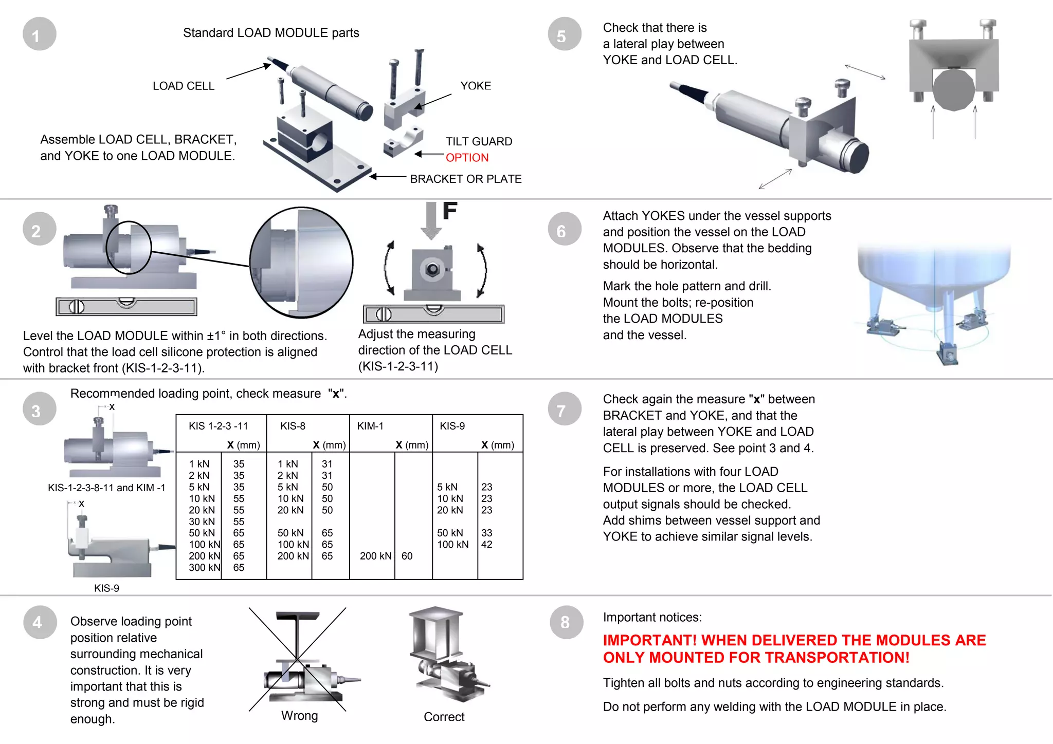

The document provides installation guidelines for load modules to ensure accurate weighing results, emphasizing the importance of using flexible connections and checking for lateral play between components. It includes technical specifications and installation steps, such as leveling the load module and ensuring proper signal levels among multiple load cells. Additionally, it contains warnings against certain actions, like performing welding with the load module in place.


