Here are the problem/symptom statements for the given numbers:
1. The motor does not spin or rotate properly.
2. The motor makes grinding or squealing noises during operation.
3. The motor shaft wobbles or is loose during operation.
4. The motor does not turn on or stop working intermittently.
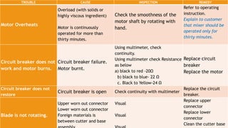
5. The motor overheats or the safety features like circuit breakers trip frequently.


![Performing Computer Operations [Autosaved].pptx](https://cdn.slidesharecdn.com/ss_thumbnails/performingcomputeroperationsautosaved-230213131335-0c4b802d-thumbnail.jpg?width=640&height=640&fit=bounds)


