Download to read offline
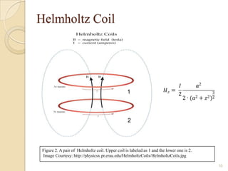
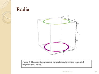
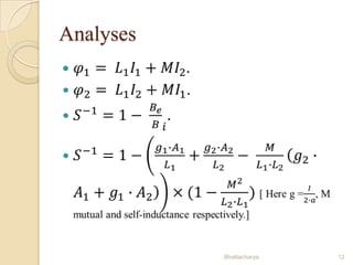
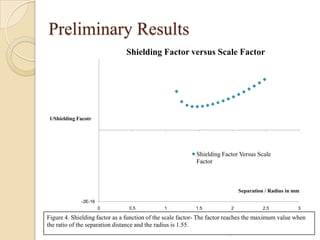

This document discusses finding the optimal setup for shielding external magnetic fields to trap Bose-Einstein condensate (BEC) atoms. It examines using two coils of the same size separated by a varying distance. Preliminary results show shielding factor is maximized when the separation distance between coils is 1.55 times the coil radius based on the Helmholtz configuration. Future work includes analytically evaluating the inverse shielding factor and developing an experiment in spring 2014.


![Getting Started with Apache Spark: Big Data Made Simple [Free Meetup]](https://cdn.slidesharecdn.com/ss_thumbnails/apachesparkgettingstarted-260203175547-8361bcc3-thumbnail.jpg?width=640&height=640&fit=bounds)


