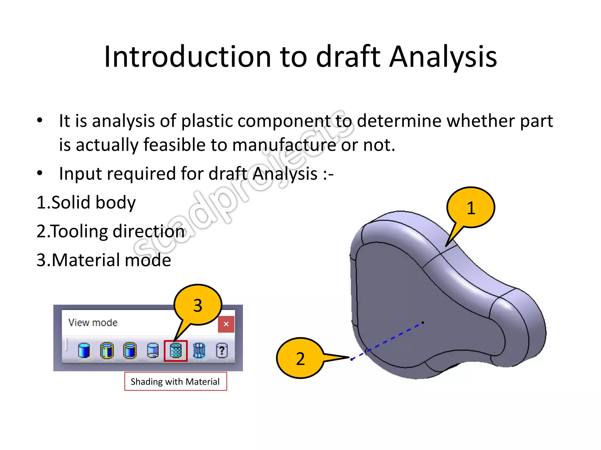
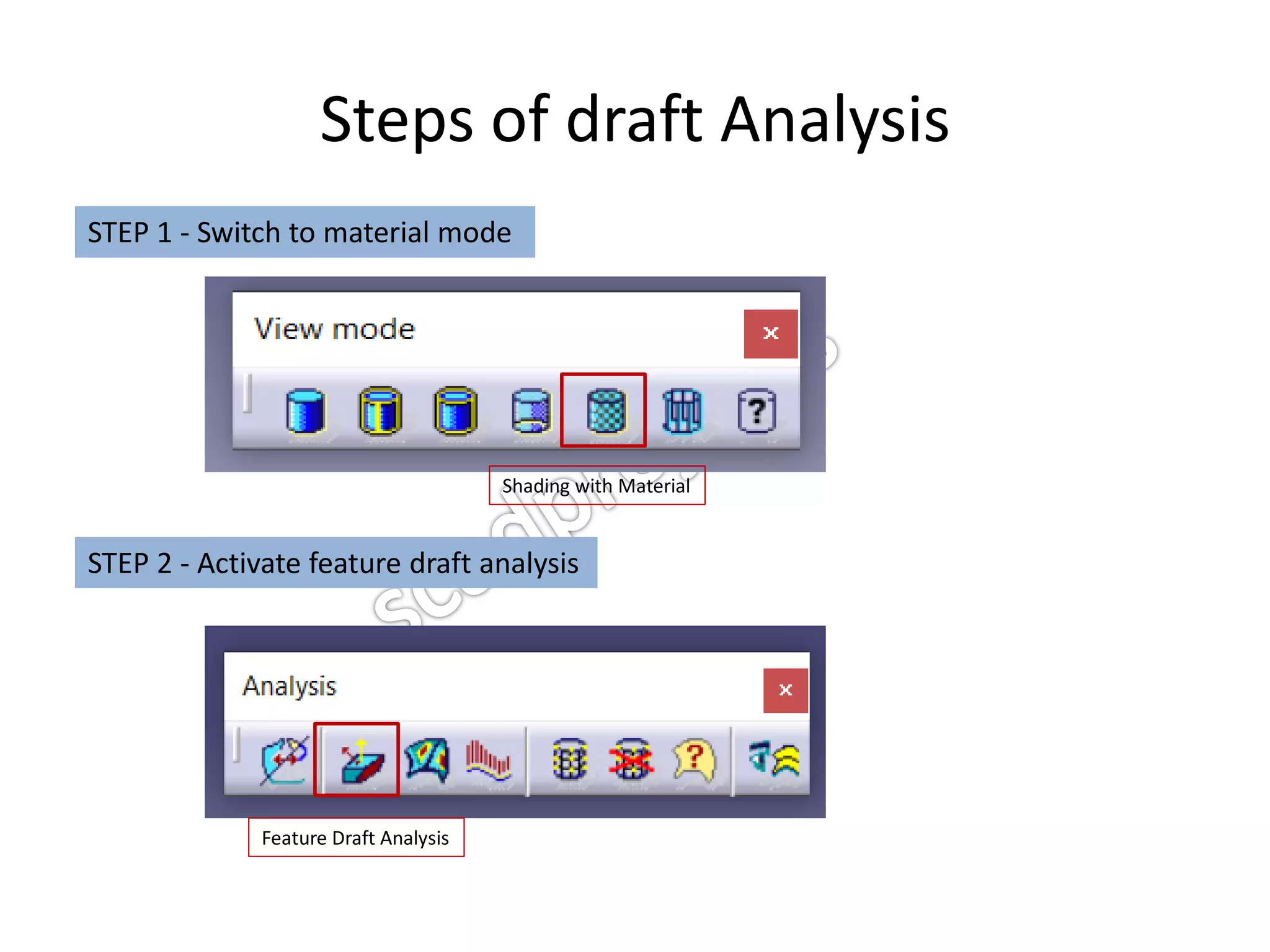
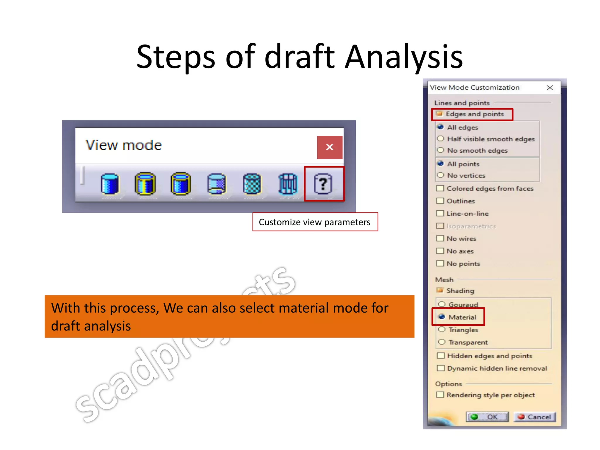
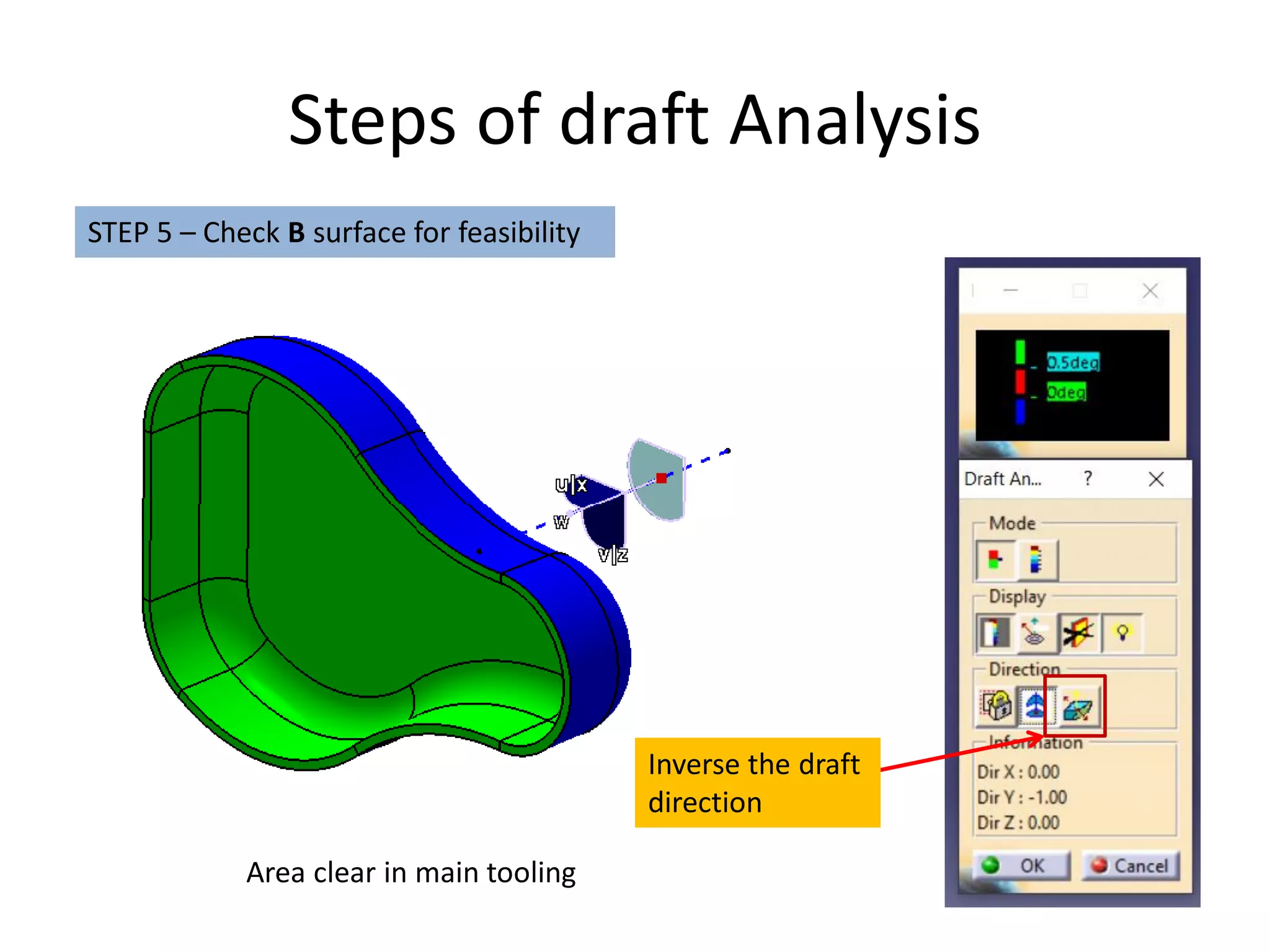
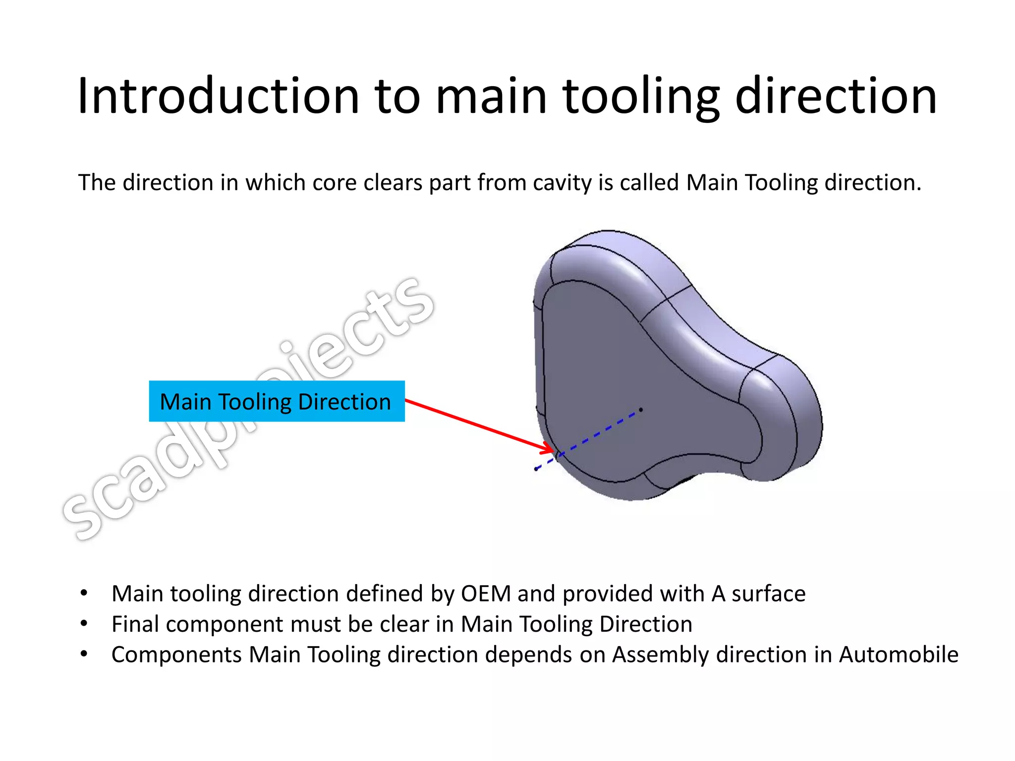
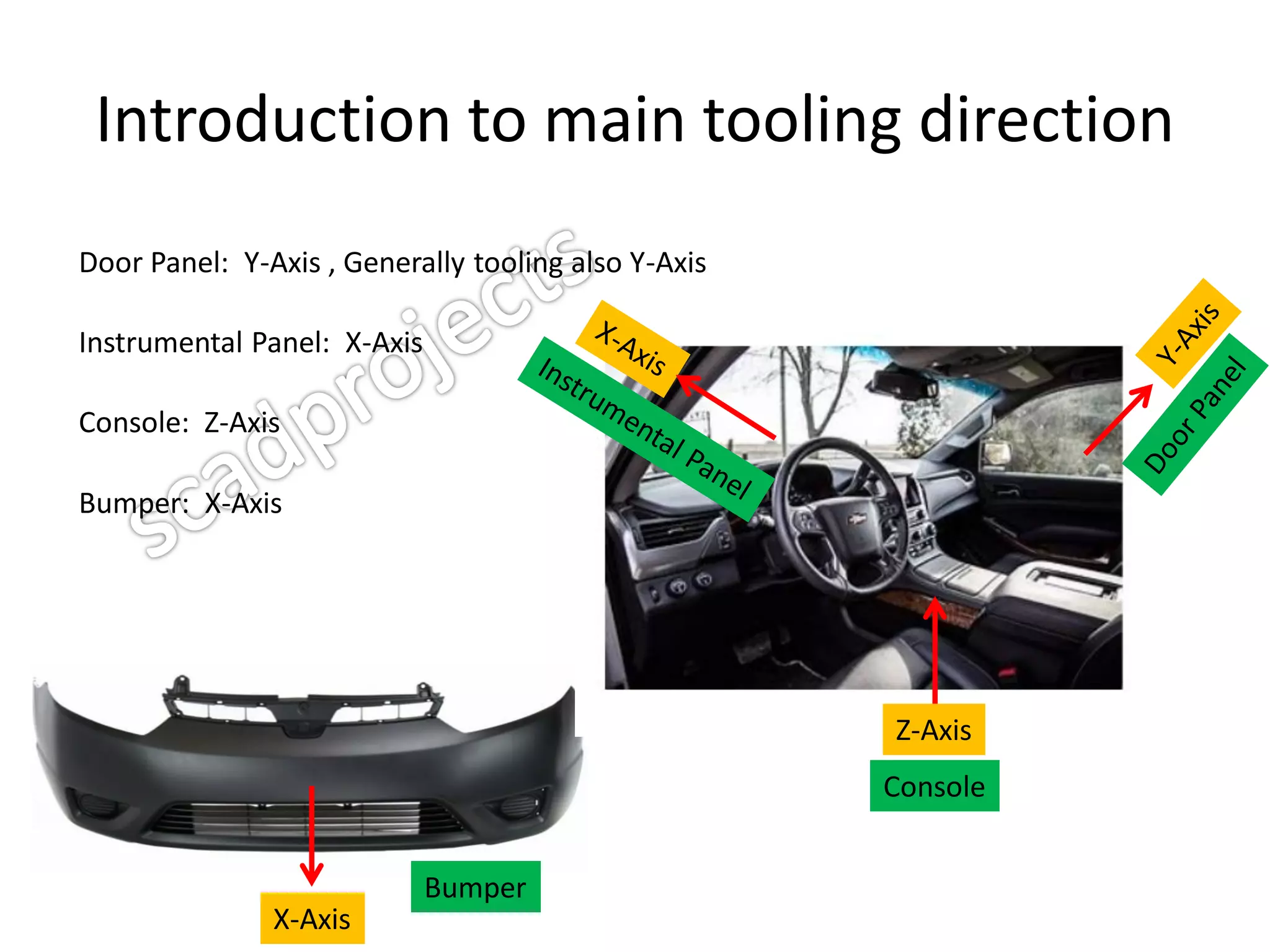
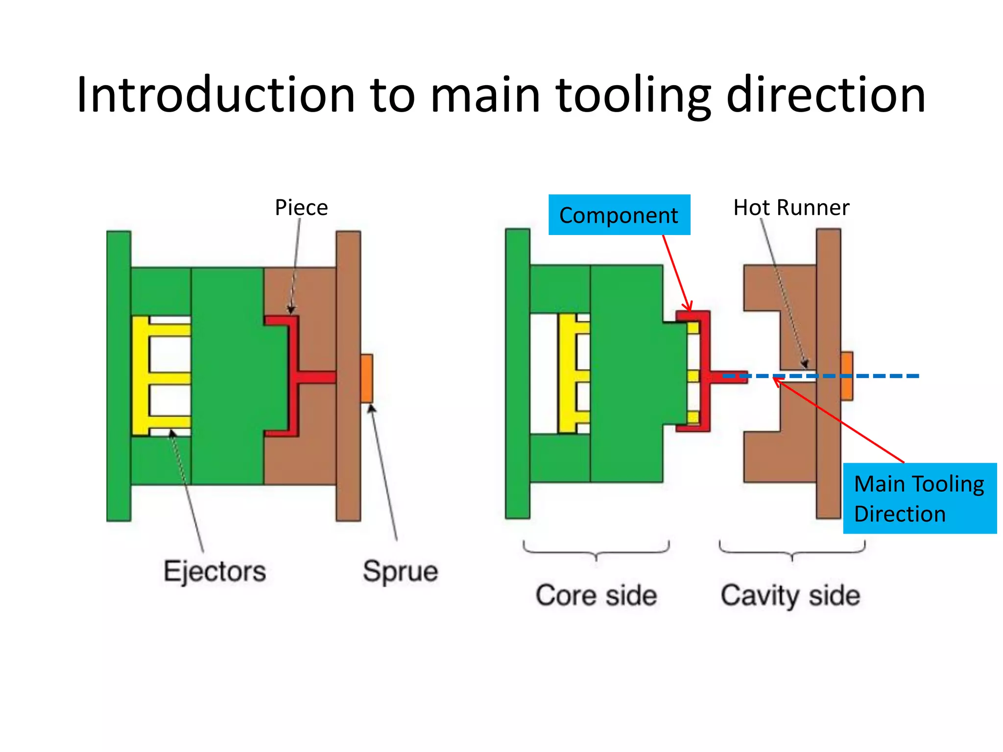
Plastic Product Design
Automotive Interior Exterior Trims
INDEX
• Introduction to draft Analysis
• Steps of draft Analysis
• Introduction to main tooling direction
• Step to create main tooling direction
• Introduction to parting line
• steps to create parting line
• Examples
Introduction to draft Analysis
• It is analysis of plastic component to determine whether part
is actually feasible to manufacture or not.
• Input required for draft Analysis :-
1.Solid body
2.Tooling direction
3.Material mode
Shading with Material
1
2
3
Steps of draft Analysis
STEP 1 - Switch to material mode
STEP 2 - Activate feature draft analysis
Feature Draft Analysis
Shading with Material
Steps of draft Analysis
Customize view parameters
With this process, We can also select material mode for
draft analysis
Steps of draft Analysis
STEP 3 – Place the compass on main tooling direction
Compass
Keep Compass logo activated
Steps of draft Analysis
STEP 4 – Set parameter as per requirement
Green Area clear in main tooling
Red Area having no draft in main tooling
Blue Area undercut in main tooling
Note: Color specified for draft
analysis may be different from
OEM to OEM
Steps of draft Analysis
STEP 5 – Click the solid body area of which draft area need to be done
Steps of draft Analysis
STEP 5 – Check A surface for feasibility
Area clear in main tooling
Steps of draft Analysis
STEP 5 – Check B surface for feasibility
Inverse the draft
direction
Area clear in main tooling
Introduction to main tooling direction
The direction in which core clears part from cavity is called Main Tooling direction.
• Main tooling direction defined by OEM and provided with A surface
• Final component must be clear in Main Tooling Direction
• Components Main Tooling direction depends on Assembly direction in Automobile
Main Tooling Direction
Introduction to main tooling direction
Door Panel: Y-Axis , Generally tooling also Y-Axis
Instrumental Panel: X-Axis
Console: Z-Axis
Bumper: X-Axis
X-Axis
Bumper
Z-Axis
Console
Introduction to main tooling direction
Piece Hot RunnerComponent
Main Tooling
Direction
Steps to create main tooling direction
STEP 1 – Draw line perpendicular to A surface of part
Steps to create main tooling direction
STEP 2 – Check with draft analysis whether area clear in Drawn direction
Area clear in main tooling
Steps to create main tooling direction
STEP 3 – If part not clear in drawn normal direction, then we need to check at
different angles line drawn to normal with trail and error method.
Area clear in main tooling
Introduction to parting line
It is edge which differentiate core and cavity
Parting Line
Introduction to parting line
STEP 2 – Study where core and cavity differentiate with help of draft analysis.
In given case green area is clear in cavity and blue area clear in core.
Parting Line can be extracted as highlighted.
Introduction to parting line
STEP 3 – Start parting line extracting with help of command EXTRACT
Parting line can be parametric non-parametric as per requirement
Introduction to parting line
STEP 4 – Modify graphic properties of fully extracted parting line as per OEM
Standard and keep in separate Geometrical set in specification tree.
Introduction to parting line
STEP 5 – Give dedicated color to main tooling, main tooling parting line , slider/lifter
parting line for easy identification.
Avoid following color which are already used by CATIA Functions
RED UPDATE NEEDED
YELLOW CONTACT DMU
MAGENTA UNION TRIM (FACES TO REMOVE)
ORANGE SELECTON
CYAN UNION TRIM (FACES TO REMOVE)
With inertia command
select given A Style.
Main Tooling Direction Creation
Task 1 : By using inertia command
Step 1 : Select A Style.
Main Tooling Direction
Step 2 : Select Create geometry then create Centre of gravity and Axis system
Create both CG & Axis system
Select create Geometry
Main Tooling Direction
Step 3 : Check draft Analysis.
Area clear in Main Tooling drawn by inertia command
Main Tooling Direction Creation
Task : By Trail and Error method
Step 1 : Select A Style.

Basics of automotive product design

  • 1.
    Plastic Product Design AutomotiveInterior Exterior Trims
  • 2.
    INDEX • Introduction todraft Analysis • Steps of draft Analysis • Introduction to main tooling direction • Step to create main tooling direction • Introduction to parting line • steps to create parting line • Examples
  • 3.
    Introduction to draftAnalysis • It is analysis of plastic component to determine whether part is actually feasible to manufacture or not. • Input required for draft Analysis :- 1.Solid body 2.Tooling direction 3.Material mode Shading with Material 1 2 3
  • 4.
    Steps of draftAnalysis STEP 1 - Switch to material mode STEP 2 - Activate feature draft analysis Feature Draft Analysis Shading with Material
  • 5.
    Steps of draftAnalysis Customize view parameters With this process, We can also select material mode for draft analysis
  • 6.
    Steps of draftAnalysis STEP 3 – Place the compass on main tooling direction Compass Keep Compass logo activated
  • 7.
    Steps of draftAnalysis STEP 4 – Set parameter as per requirement Green Area clear in main tooling Red Area having no draft in main tooling Blue Area undercut in main tooling Note: Color specified for draft analysis may be different from OEM to OEM
  • 8.
    Steps of draftAnalysis STEP 5 – Click the solid body area of which draft area need to be done
  • 9.
    Steps of draftAnalysis STEP 5 – Check A surface for feasibility Area clear in main tooling
  • 10.
    Steps of draftAnalysis STEP 5 – Check B surface for feasibility Inverse the draft direction Area clear in main tooling
  • 11.
    Introduction to maintooling direction The direction in which core clears part from cavity is called Main Tooling direction. • Main tooling direction defined by OEM and provided with A surface • Final component must be clear in Main Tooling Direction • Components Main Tooling direction depends on Assembly direction in Automobile Main Tooling Direction
  • 12.
    Introduction to maintooling direction Door Panel: Y-Axis , Generally tooling also Y-Axis Instrumental Panel: X-Axis Console: Z-Axis Bumper: X-Axis X-Axis Bumper Z-Axis Console
  • 13.
    Introduction to maintooling direction Piece Hot RunnerComponent Main Tooling Direction
  • 14.
    Steps to createmain tooling direction STEP 1 – Draw line perpendicular to A surface of part
  • 15.
    Steps to createmain tooling direction STEP 2 – Check with draft analysis whether area clear in Drawn direction Area clear in main tooling
  • 16.
    Steps to createmain tooling direction STEP 3 – If part not clear in drawn normal direction, then we need to check at different angles line drawn to normal with trail and error method. Area clear in main tooling
  • 17.
    Introduction to partingline It is edge which differentiate core and cavity Parting Line
  • 18.
    Introduction to partingline STEP 2 – Study where core and cavity differentiate with help of draft analysis. In given case green area is clear in cavity and blue area clear in core. Parting Line can be extracted as highlighted.
  • 19.
    Introduction to partingline STEP 3 – Start parting line extracting with help of command EXTRACT Parting line can be parametric non-parametric as per requirement
  • 20.
    Introduction to partingline STEP 4 – Modify graphic properties of fully extracted parting line as per OEM Standard and keep in separate Geometrical set in specification tree.
  • 21.
    Introduction to partingline STEP 5 – Give dedicated color to main tooling, main tooling parting line , slider/lifter parting line for easy identification. Avoid following color which are already used by CATIA Functions RED UPDATE NEEDED YELLOW CONTACT DMU MAGENTA UNION TRIM (FACES TO REMOVE) ORANGE SELECTON CYAN UNION TRIM (FACES TO REMOVE)
  • 22.
    With inertia command selectgiven A Style. Main Tooling Direction Creation Task 1 : By using inertia command Step 1 : Select A Style.
  • 23.
    Main Tooling Direction Step2 : Select Create geometry then create Centre of gravity and Axis system Create both CG & Axis system Select create Geometry
  • 24.
    Main Tooling Direction Step3 : Check draft Analysis. Area clear in Main Tooling drawn by inertia command
  • 25.
    Main Tooling DirectionCreation Task : By Trail and Error method Step 1 : Select A Style.