Downloaded 31 times


![MAINTENANCE MANUAL F O R LABORATORY EQUIPMENT
13
Chapter 3
pH Meter
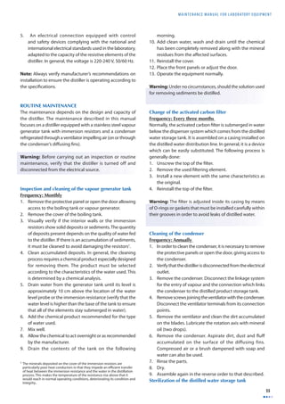
GMDN Code 15164
ECRI Code 15-164
Denomination pH Meter
The pH meter is used for determining the concentration of
hydrogen ions [H+] in a solution. This equipment, provided
it is carefully used and calibrated, measures the acidity of
an aqueous solution. pH meters are sometimes called pH
analysers, pH monitors or potentiometers.
PURPOSE OF THE EQUIPMENT
The pH meter is commonly used in any fi eld of science
related to aqueous solutions. It is used in areas such as
agriculture, water treatment and purifi cation, in industrial
processes such as petrochemicals, paper manufacture,
foods, pharmaceuticals, research and development, metal
mechanics, etc. In the health laboratory, its applications
are related to the control of culture mediums and to the
measurement of the alkalinity or acidity of broths and
buff ers. In specialized laboratories, diagnostic equipment
microelectrodes are used to measure the pH of liquid
blood components. The plasma pH allows the patient’s
health to be evaluated. It normally measures between 7.35
and 7.45. This value relates to the patient’s metabolism
in which a multitude of reactions occurs where acids and
bases are normally kept in balance. Acids constantly liberate
hydrogen ions [H+] and the organism neutralizes or balances
acidity by liberating bicarbonate ions [HCO–]. The acid-base
3
ratio in the organism is maintained by the kidneys, (organs
in which any excesses present are eliminated). The plasma
pH is one of the characteristics that vary with factors such
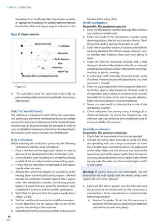
as age or state of health of the patient. Table 1 shows typical
pH values of some bodily fl uids.
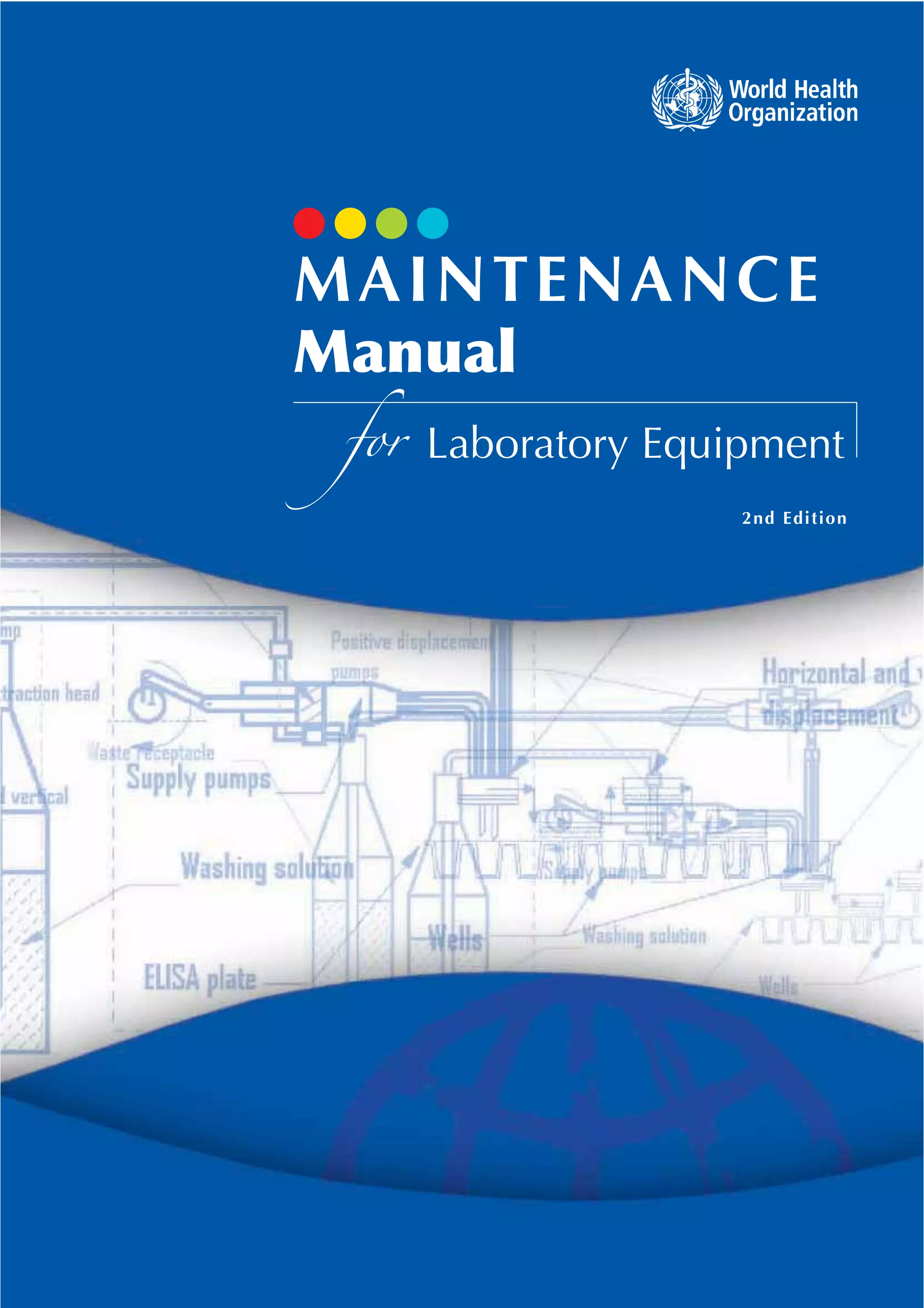
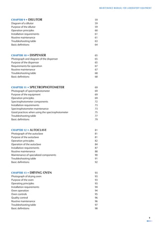
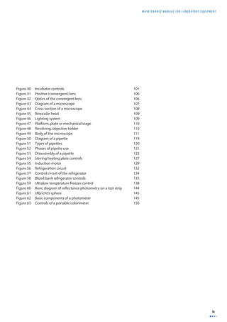
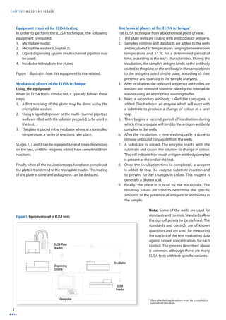
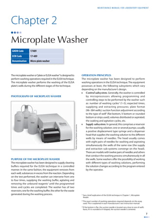
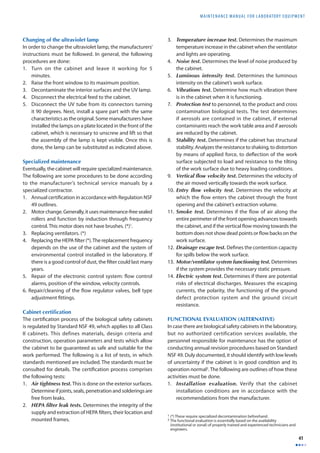
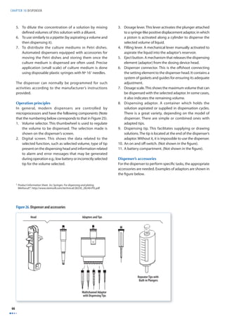
PHOTOGRAPH AND COMPONENTS OF THE
pH METER
1
3
2
OPERATION PRINCIPLES
The pH meter measures the concentration of hydrogen ions
[H+] using an ion-sensitive electrode. Under ideal conditions,
this electrode should respond in the presence of only
one type of ion. In reality, there are always interactions or
interferences with other types of ions present in the solution.
A pH electrode is generally a combined electrode, in which
a reference electrode and an internal glass electrode are
integrated into a combined probe. The lower part of the
probe ends in a round bulb of thin glass where the tip
of the internal electrode is found. The body of the probe
pH values of some bodily fl uids
Fluid pH Value
Bile 7.8 – 8.6
Saliva 6.4 – 6.8
Urine 5.5 – 7.0
Gastric Juice 1.5 – 1.8
Blood 7.35 – 7.45
Photo courtesy of Consort
1 Electrode carrying arm and electrode
2 Digital display
3 Control panel with temperature adjustment control, mode
selection (Standby/mV/pH) and calibration controls](https://image.slidesharecdn.com/b2df9d01-141207144322-conversion-gate01/85/B2-df9d01-26-320.jpg)
![CHAPTER 3 pH METER
14
contains saturated potassium chloride (KCl) and a solution
0.1 M of hydrogen chloride (HCl). The tip of the reference
electrode’s cathode is inside the body of the probe. On the
outside and end of the inner tube is the anodized end. The
reference electrode is usually made of the same type of
material as the internal electrode. Both tubes, interior and
exterior, contain a reference solution. Only the outer tube
has contact with the measured solution through a porous
cap which acts as a saline bridge.
This device acts like a galvanized cell. The reference electrode
is the internal tube of the pH meter probe, which cannot lose
ions through interactions with the surrounding environment.
Therefore as a reference, it remains static (unchangeable)
during the measuring process. The external tube of the
probe contains the medium which is allowed to mix with
the external environment. As a result, this tube must be
fi lled periodically with a potassium chloride solution (KCI)
for restoring the capacity of the electrode which would
otherwise be inhibited by a loss of ions and evaporation.
The glass bulb on the lower part of the pH electrode acts
as a measuring element and is covered with a layer of
hydrated gel on its exterior and interior. Metallic sodium
cations [Na+] are diff used in the hydrated gel outside of
the glass and in the solution, while the hydrogen ions [H+]
are diff used in the gel. This gel makes the pH electrode
ion-selective: Hydrogen ions [H+] cannot pass through the
glass membrane of the pH electrode. Sodium ions [Na+] pass
through and cause a change in free energy, which the pH
meter measures. A brief explanation of the theory on how
electrodes function is included in the appendix at the end
of the chapter.
pH METER COMPONENTS
A pH meter generally has the following components:
1. The body of the instrument containing the circuits,
controls, connectors, display screens and measuring
scales. The following are among some of its most
important components:
a) An ON and OFF switch. Not all pH meters have an
on and off switch. Some simply have a cord with a
plug which allows it to be connected to a suitable
electrical outlet.
b) Temperature control. This control allows
adjustments according to the temperature of the
solution measured.
c) Calibration controls. Depending on the design,
pH meters possess one or two calibration buttons
or dials. Normally these are identifi ed by Cal 1 and
Cal 2. If the pH meter is calibrated using only one
solution, the Cal 1 button is used; making sure
that Cal 2 is set at a 100%. If the pH meter allows
two point calibrations, two known pH solutions
covering the range of pH to be measured are used.
In this case, the two controls are used (Cal 1 and Cal
2). In special cases, a three-point calibration must
be done (using three known pH solutions).
d) Mode selector. The functions generally included
in this control are:
I. Standby mode (0). In this position the electrodes
are protected from electrical currents. It is the
position used for maintaining the equipment
while stored.
II. pH mode. In this position the equipment can
take pH measurements after performing the
required calibration procedures.
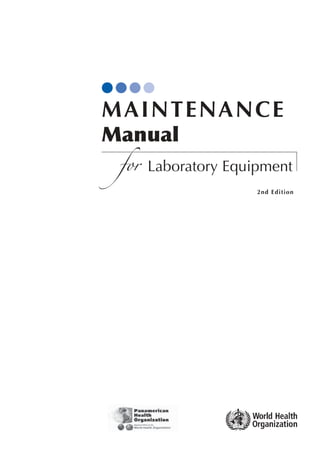
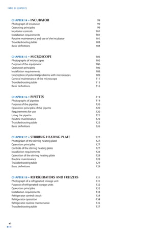
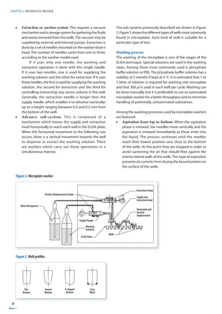
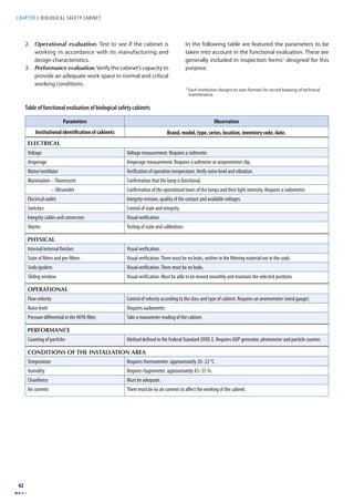
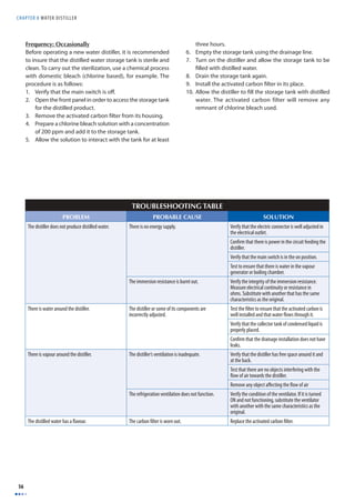
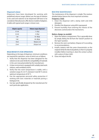
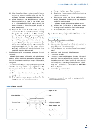
4
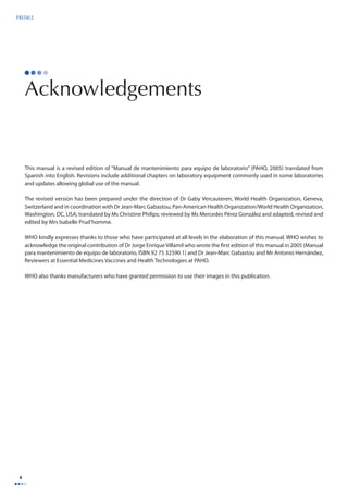
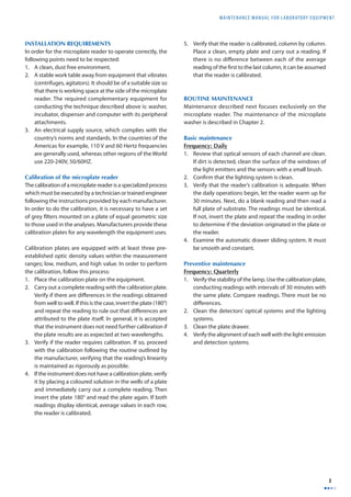
High Impedance
Voltmeter
KCI KCI
Temperature
Regulator
Reference
Terminal
Saline Mesh Bridge Solution Under Analysis
Ag/AgCI Electrode
Active Termimal
Special Glass Permeable to Ions
Figure 4. Diagram of a pH meter](https://image.slidesharecdn.com/b2df9d01-141207144322-conversion-gate01/85/B2-df9d01-27-320.jpg)
![MAINTENANCE MANUAL F O R LABORATORY EQUIPMENT
15
III. Millivolt mode (mV). In this position the
equipment is capable of performing millivoltage
readings.
IV. ATC mode. The automatic temperature control
mode is used when the pH is measured in
solutions for which the temperature varies. This
function requires the use of a special probe. Not
all pH meters have this control.
2. A combined electrode or probe. This device must
be stored in distilled water and stay connected to the
measuring instrument. A combination electrode has a
reference electrode (also known as Calomel electrode)
and an internal electrode, integrated into the same body.
Its design varies depending on the manufacturer.
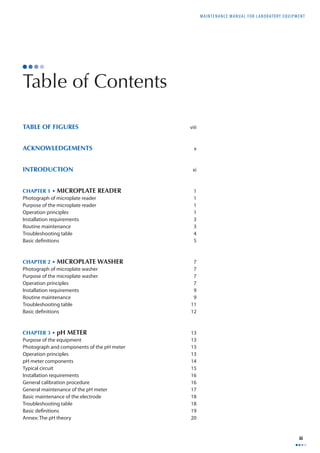
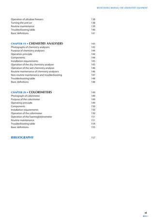
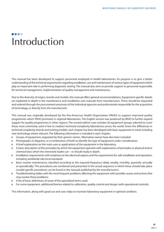
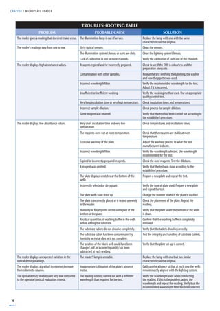
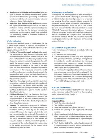
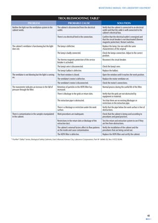
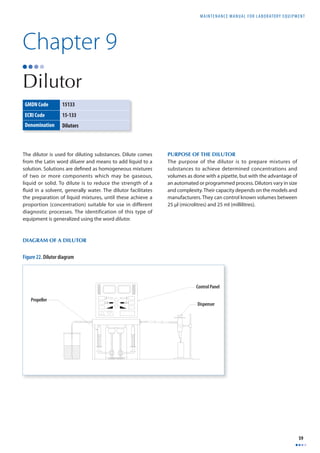
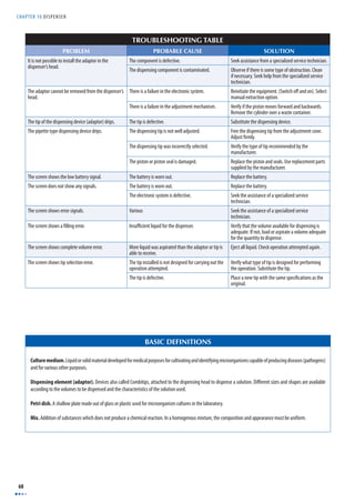
TYPICAL CIRCUIT
Figure 6 features a typical circuit adapted to the control
system of the pH meter. Each manufacturer has its own
designs and variations.
Figure 5. Types of electrodes
110 VAC
Combined Electrode
1N 4002
Silver Wire (Ag)
Reference Electrode
Semi-Permeable Mesh
Buffer Solution
7812
3,300
mfd
0.1
mfd
3,300
mfd
0.1
mfd
7912
10K
Variable
resistor
12V
Lamp
Entrance
2 7
10K
Reference
560K
pH
30K
mV
9,09 K
1,00 K
TL081
Transformer
110 V AC/ 12 V DC
10K
Zero
3
6
Exit
pH
mV
4
5
1
Figure 6. Example of a typical pH meter control circuit
Platinum Wire (Pi)
Reference Electrode (Calomel)
h
Mercury [Hg]
Mercury Chloride [Hg CI]
Potassium Chloride
Porous Stopper](https://image.slidesharecdn.com/b2df9d01-141207144322-conversion-gate01/85/B2-df9d01-28-320.jpg)
![MAINTENANCE MANUAL F O R LABORATORY EQUIPMENT
19
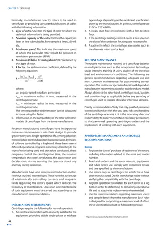
BASIC DEFINITIONS
Buff er. A solution containing either a weak acid and its salt or, a weak base and its salt, which makes it resistant to changes in pH at a given temperature.
Calomel electrode. A reference electrode used with the active electrode for determining the pH of a solution. This electrode is constructed with a mercury base
(Hg), a covering of dimercuric chloride (Hg2Cl2) and a potassium chloride solution of 0.1 M. It is represented as Cl2[Hg2Cl2, KCl]Hg.
Dissociation. A phenomenon through which a break in the molecules occurs. As a result it produces electrically charged particles (ions).
Electrolyte. A solute which produces a conducting solution, e.g. NaCl (sodium chloride) and NH4OH.
Gel. A semisolid substance (e.g. jelly) composed of a colloid (solid) dispersed in a liquid medium.
Ion. Neutral atom which gains or loses an electron. When the atom loses an electron, it becomes a positively charged ion, called a cation. If the atom gains or captures
an electron, it becomes a negatively charged ion, called an anion.
Ion-sensitive electrode. A device which produces a diff erence in potential proportional to the concentration of an analyte.
Molarity. Number of Moles (M) in a substance in a litre of solution. (Number of moles of solute in a litre (L) of solution). The brackets around the ionic symbol
indicate that it is treated as a molar concentration.
Mol. (abbreviation for molecule). A quantity of any substance whose mass expressed in grams is numerically equal to its atomic mass.
Mole (unit). The amount of a substance that contains as many atoms, molecules, ions, or other elementary units as the number of atoms in 0.012 kilogram of
carbon 12. It corresponds to the number 6.0225 × 10²³, or Avogadro’s number, also called gram molecule.
The mass in grams of this amount of a substance, numerically equal to the molecular weight of the substance, also called gram-molecular weight.
pH. Measurement of the concentration of the hydrogen ion (H+) given in moles per litre (M) in a solution. The pH concept was proposed by Sørensen and Lindstrøm-
Lang in 1909 to facilitate expressing very low ion concentrations. It is defi ned by the following equation:
pH = –log [H+] or [H+] = 10-pH
It measures the acidity of a solution. Example, in water the concentration of [H+] is 1.0 x 10⁻⁷ M resulting in pH = 7. This allows the range of concentrations from
1 to 10-14 M, to be expressed from zero (0) to 14. There are diverse systems for measuring the acidity of a solution. An acidic substance dissolved in water is capable
of producing H+ ions. A basic substance dissolved in water is capable of producing [OH–] (hydroxides) ions.
An acid substance has a greater quantity of ions [H+] than pure water; a basic substance shows greater quantities of ions [OH–] than pure water. The concentrations
of substances are expressed in moles per litre.
In pure water, the ion concentration [H+] and [OH–] is 1.0 x 10⁻⁷ M, it is thus considered a neutral substance. In reality, it is a weak electrolyte that is dissociated
following the following equation:
H2O ' [H+][OH–]
In all aqueous solutions there is a balance expressed as:
[H+][OH–] = K
H2O
If the solution is diluted, the concentration of the non-dissociated water can be considered constant:
[H+][OH–] = [H2O]K = Ka
The new constant Ka is called a constant of dissociation or ionic product of water and its value is 1.0x10⁻¹⁴ at 25 °C.
[H+][OH–] = 1.0 x 10⁻¹⁴
X x X = 1.0 x 10-14
X2 = 1.0 x 10⁻¹⁴
X = 1.0 x 10⁻⁷
In pure water the concentrations of H+ and OH– are 1.0 x 10⁻⁷ M, a very low concentration, given that the molar concentration of water is 55.4 mol/litre.
Solution. Homogenous liquid mixture (with uniform properties) of two or more substances. It is characterized by the absence of chemical reactions among the
components in the mixture. The component in greater proportion and generally in a liquid state is called solvent and that or those in a lesser quantity, the solutes.](https://image.slidesharecdn.com/b2df9d01-141207144322-conversion-gate01/85/B2-df9d01-32-320.jpg)
![CHAPTER 3 pH METER
20
Annex
The pH theory
pH electrodes ideally behave as an electrochemical cell and react to the concentration of ions [H+]. This generates an
electromotive force (EMF) which, according to the Nernst law is calculated using the following equation:
E = E o + RT
Given that:
nF
lnaH L where a is the eff ective concentration of ions (Activity)
If n = 1, the equation is then rewritten as:
E = E o − R'T
F
pH
E° is a constant dependant on the temperature. If E° is substituted by E’T, the calibration will be more sensitive. Real electrodes
do not always perform according to the Nernst equation. If the concept of sensibility (s) is introduced, the equation can be
rewritten as:
E = E 'T − s
R'T
F
pH
The values of E’ and s are found when measuring the EMF in two solutions with known pH. S is the slope of E versus pH,
while E’ is found at the intersection with the axis y. When E’ and s are known, the equation can be rewritten and the pH can
be calculated as:
pH = E 'T − E
s
R'T
T
ln aH
pH = lnaH](https://image.slidesharecdn.com/b2df9d01-141207144322-conversion-gate01/85/B2-df9d01-33-320.jpg)
![MAINTENANCE MANUAL F O R LABORATORY EQUIPMENT
21
Chapter 4
Balances
GMDN Code 10261 10263 45513 46548
ECRI Code 10-261 10-263 18-449 18-451
Denomination Balances Electronic balances Analytical electronic
The balance is an instrument which measures the mass of
a body or substance using the gravity force which acts on
that body. The word comes from the Latin terms bis which
means two and lanx, plate. The balance has other names
such as scale and weight. It must be taken into account that
the weight is the force which the gravitational fi eld exercises
balances
Micro analytical,
microelectronic
balances
on a body’s mass, this force being the product of the mass
by the local acceleration of gravity [F = m x g]. The term
local is used to emphasize that this acceleration depends
on factors such as the geographical latitude, altitude and
the Earth’s density where the measurement is taken. This
force is measured in Newtons.
Photo courtesy of Acculab Corporation
Photo courtesy of Ohaus Corporation
PHOTOGRAPHS OF BALANCES
Mechanical balance Electronic balance](https://image.slidesharecdn.com/b2df9d01-141207144322-conversion-gate01/85/B2-df9d01-34-320.jpg)
![CHAPTER 4 BALANCES
22
PURPOSE OF THE BALANCE
The balance is used for measuring the mass of a body or
substance or its weight. In the laboratory, the balance is used
for weighing as part of quality control activities (on devices
like pipettes), in the preparation of mixtures of components
in predefined proportions and in the determination of
specifi c densities or weights.
OPERATION PRINCIPLES
There are diff erences in design, principles and criteria of
metrology amongst balances. At present, there are two large
groups of balances: mechanical and electronic balances.
Mechanical balances
The following are some of the more common ones:
1. Spring balance. Its function is based on a mechanical
property of springs as the force exercised on a spring
is proportional to the spring’s elasticity constant [k],
multiplied by its elongation [x] [F = -kx]. The greater
the mass [m] placed on the balance’s plate, the greater
the elongation will be, given that the elongation is
proportional to the mass and the spring’s constant. The
calibration of a spring balance depends on the force
of gravity acting on the object weighed. This type of
balance is used when great precision is not necessary.
2. Sliding weight balance. This type of balance is
equipped with two known weights which can be moved
on setting scales (one macro, the other micro). Upon
placing a substance of unknown mass on the tray, its
weight is determined by moving the weight on both
setting scales until the equilibrium position is reached.
At this point, the weight is obtained by adding both
quantities indicated by the sliding masses’ position on
the scale.
3. Analytical balance. This balance functions by comparing
known weight masses with that of a substance of
unknown weight. It is composed of a base on a bar or
symmetrical lever, maintained by a blade-like support
on a central point called a fulcrum. At its ends, there
are stirrups, also supported with blades which allow
these to oscillate smoothly. From there, two plates
are suspended. Certifi ed weights are placed on one
of the plates and unknown weights on the other. The
balance has a securing system or lock, which allows
the main lever to remain stable when not in use or
when it is necessary to modify the counter-weights. The
balance is inside an external box which protects it from
interferences, such as air currents. Analytical balances
can weigh ten thousandths of a gram (0.0001 g) or 100
thousandths of a gram (0.00001 g). This type of balance
generally has a capacity of up to 200 grams.
X
Spring Without Load
Displacement
Measuring Scale
Mass
F=-kx
F=mg
Spring With Load
m
F = F1
-kx = mg
Figure 7. Spring balance
Tray
Macro Scale
Micro Sliding Weight
Macro Sliding Weight
Micro Scale
Figure 8. Sliding weight scale
Figure 9. Analytical balance](https://image.slidesharecdn.com/b2df9d01-141207144322-conversion-gate01/85/B2-df9d01-35-320.jpg)
![CHAPTER 4 BALANCES
24
4. Verify the plate’s brake. It is mounted on a threaded
axis which touches the plate in order to prevent it from
oscillating when the balance is locked. In case of an
imbalance, the axis must be rotated slightly until the
distance between the break and the plate is zero when
the balance is locked.
Maintenance of the mechanical balance
The maintenance of mechanical balances is limited to the
following routines:
Frequency: Daily
1. Verify the level.
2. Verify the zero setting.
3. Verify the sensitivity adjustment.
4. Clean the weighing plate.
Frequency: Annually
1. Calibrate the balance and document the process.
2. Disassemble and clean the internal components. This
must be done according to the process outlined by the
manufacturer or a specialized fi rm must be contracted
to do so.
Electronic balances
The electronic balances have three basic components:
1. A weighing plate. The object to be weighed placed
on the weighing plate exercises a pressure distributed
randomly over the surface of the plate. By means of
a transfer mechanism (levers, supports, guides), the
weight’s load is concentrated on a simple force [F] which
can be measured. [F = ∫P∂a]. The pressure’s integral part
on the area allows the force to be calculated.
2. A measuring device known as “load cell” produces an
exit signal corresponding to the load’s force in the form
of changes in the voltage or frequency.
3. A digital analogous electronic circuit shows the fi nal
result of the weight digitally.
Laboratory balances operate according to the principle
of compensation of the electromagnetic force applicable
to displacements or torques. The combination of their
mechanical components and automatic reading systems
provides weight measurements at defi ned levels of accuracy
depending on the model.
Principle. The mobile parts (weighing plate, support
column [a], bobbin, position and load indicator [G] -the
object in the process of being weighed-) are maintained
in equilibrium by a compensation force [F] equal to the
weight. The compensation force is generated by an electrical
current through a bobbin in the air gap of a cylindrical
electromagnet. The force F is calculated with the equation
[F = I x L x B] where: I = electrical intensity, L = total length
of the wire of the coil and B = magnetic fl ow intensity in the
electromagnet’s air gap.
With any change in the load (weight/mass), the mobile
mechanical system responds by moving vertically a fraction
of distance. Detected by a photosensor [e], an electrical
signal is sent to the servo-amplifi er [f ]. This changes the
fl ow of electrical current passing through the bobbin of the
magnet [c] in such a manner that the mobile system returns
to the balanced position upon adjusting of the magnetic
fl ow in the electromagnet. Consequently, the weight of
the mass [G] can be measured indirectly at the start of the
electrical current fl ow, which passes through the circuit
measuring the voltage [V] by means of a precision resistor
[R], [V = I x R]. To date, many systems developed use the
electronic system for carrying out very exact measurements
of mass and weight. The following diagram explains how
electronic balances function.
Figure 12. Components of electronic balances
Transfer
Mechanism
Load Cell
Screen and
Signal Processor
P
Figure 13. Compensation force principle
G
b
a
e
f
c d
R V=I*R
I](https://image.slidesharecdn.com/b2df9d01-141207144322-conversion-gate01/85/B2-df9d01-37-320.jpg)
![MAINTENANCE MANUAL F O R LABORATORY EQUIPMENT
25
The signal processing system
The signal processing system is composed of the circuit which
transforms the electrical signal emitted by the transducer
into numerical data which can be read on a screen. The
signal process comprises the following functions:
1. Tare setting. This setting is used to adjust the reading
value at zero with any load within the balance’s capacity
range. It is controlled by a button generally located on
the front part of the balance. It is commonly used for
taring the weighing container.
2. Repeatability setting control. During a reading, weighed
values are averaged within a predefi ned period of time.
This function is very useful when weighing operations
need to be carried out in unstable conditions, e.g. in
the presence of air currents or vibrations. This control
defi nes the time period allowed for a result to lie within
preset limits for it to be considered stable. In addition,
it can be adjusted to suit a particular application.
3. Rounding off. In general, electronic balances process
data internally at a greater resolution than shown on the
screen. The internal net value rounded off is displayed
on the screen.
4. Stability detector. This light indicator fades when the
weighing result becomes stable and is ready to be
read. Alternatively in other balance models, this feature
allows the display of the result on the screen when the
measure of the weight becomes stable.
5. Electronic signalling process. It allows the processing
and display of the weighing operation results. It may also
allow other special functions such as piece counting,
percentage weighing, dynamic weighing of unstable
weight (e.g. animals), and formula weighing, among
others. The calculations are done by the microprocessor
following the instructions entered by the operator on
the balance’s keyboard.
Classification of balances
The International Organization of Legal Metrology (OIML)
has classifi ed the balances into four groups:
• Group I: special exactitude
• Group II: high exactitude
• Group III: medium exactitude
• Group IV: ordinary exactitude
The graph in Figure 14 shows the above-mentioned
classifi cation.
In the metrological classifi cation of electronic balances, only
two parameters are of importance:
1. The maximum load [Max.]
2. The value of the digital division [d]1
The number of the scale’s divisions is calculated by means
of the following formula.
n = Max
dd
The OIML accepts the following convention for laboratory
balances.
1. Ultramicroanalytics dd = 0.1 μg
2. Microanalytics dd = 1 μg
3. Semi-microanalytics dd = 0.01 mg
4. Macroanalytics dd = 0.1 mg
5. Precision dd ≥ 1 mg
1 Kupper, W., Balances and Weighing, Mettler Instrument Corp., Princeton-
Hightstown, NJ.
Figure 14. Classifi cation of balances by exactitude](https://image.slidesharecdn.com/b2df9d01-141207144322-conversion-gate01/85/B2-df9d01-38-320.jpg)
![MAINTENANCE MANUAL F O R LABORATORY EQUIPMENT
29
BASIC DEFINITIONS
ASTM. American Society of Testing and Materials.
Calibration. Determination of the correct value of an instrument’s reading by measurement or comparison against a standard or norm. A balance is calibrated by
using standard weights.
Certifi ed masses. Masses conforming to the tolerance defi ned by the certifi cation bodies. The ASTM classes 1 to 4 standards are those most widely used and must
be used (a compulsory reference) for performing the calibration routines.
Exactitude. The sum of all the balance’s errors. This is called total error band.
Hysteresis. The diff erence in the results when the load in the balance is increased or decreased.
Lateral load. A balance’s ability to consistently read the value of masses, no matter where they are placed on the weighing scale. This is also called corner load.
Lateral load error. A deviation in the results when an object is weighed placing it in diff erent parts of the weighing plate, i.e. in the centre of the plate and on
one of its sides.
Linear error. A diff erence showed when the balance is loaded in a successive manner, increasing the quantity of weight in equal magnitude until it reaches its
maximum capacity and unloaded in an analogous process. The diff erences shown between the readings obtained and the arithmetic values corresponding to the
weights used are interpreted as non-linearity.
Linearity. Refers to the ability of a balance to perform accurate readings of weights throughout its weighing capacity . A graph showing weight compared to the
weight indication on a perfectly linear balance should generate a straight line. In order to determine the linear error of a balance, certifi ed masses must be used.
The procedure allows the linear diff erences to be calculated by reading certifi ed masses with and without preloading. The diff erence between the readings allows
the linear error to be calculated.
Mass. A physical property of the bodies related to the quantity of matter, expressed in kilograms (kg), these contain. In physics, there are two quantities to which
the name mass is given: gravitational mass which is a measure of the way a body interacts with the gravitational fi eld (if the body’s mass is small, the body
experiences a weaker force than if its mass were greater) and the inertial mass, which is a quantitative or numerical measure of a body’s inertia, that is, of its
resistance to acceleration. The unit for expressing mass is the kilogram [kg].
OIML. International Offi ce of Legal Metrology.
Sensitivity. The smallest mass detected by the balance or the smallest mass that the balance can measure correctly.
Sensitivity error. Constant deviation throughout the weighing range or capacity of a balance.
Traceability. The ability to relate the measurements of an instrument to a defi ned standard.](https://image.slidesharecdn.com/b2df9d01-141207144322-conversion-gate01/85/B2-df9d01-42-320.jpg)

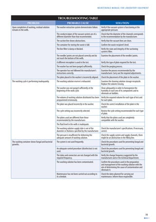
![CHAPTER 5 WATER BATHS
34
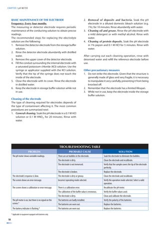
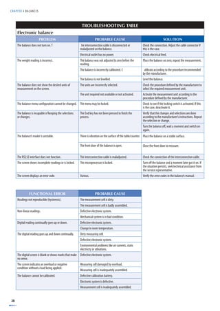
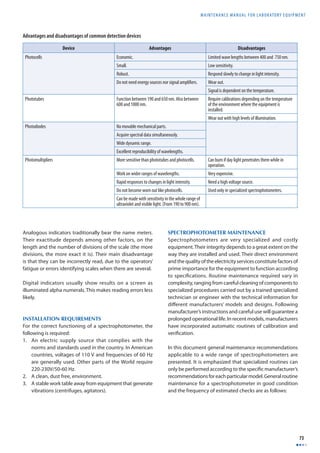
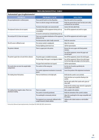
TROUBLESHOOTING TABLE
PROBLEM PROBABLE CAUSE SOLUTION
There is no power to the instrument. The water bath is disconnected. Connect the water bath.
The switch is defective. Change the switch.
The fuse is defective. Substitute the fuse.
The water bath is not getting hot. The temperature control not set. Set the temperature control.
The resistor(s) is/are defective. Change resistor(s).
The limit control is not set Set the limit control.
The temperature is higher than that selected. The temperature control is defective. Change the temperature control if required.
Verify the selection of the parameters.
The samples are warmed slowly. The tank is empty or contains very little fl uid. Fill the tank up to the recommended level.
The temperature is increasing very slowly. The resistor(s) is/are defective. Change the resistor(s).
The temperature control is defective. Substitute temperature control.
BASIC DEFINITIONS
Circulator. An apparatus that shakes or stirs fl uids to keep their properties (temperature, color, density) homogenous. These are also called agitators.
Diff using tray. Device located at the bottom of the water bath to support the containers located inside the tank. It also allows thermal convection currents generated
in the fl uid contained in the tank to circulate from top to bottom and back to the top, maintaining the temperature homogeneous at the level selected by the operator.
In general the diff using tray is made of stainless steel.
Electrostatic painting. A painting process that uses the particle-attracting property of electrostatic charges. A potential diff erence of 80-150kV is applied to a
grid of wires through which the paint is sprayed to charge each particle. The metal objects to be sprayed are connected to the opposite terminal of the high-voltage
circuit, so that they attract the particles of paint. The piece covered with paint particles is then placed in an electrical oven to melt the particles, making them adhere
strongly to the piece.
Fuse. A safety device which protects the electrical circuits from excessive current. Fuses are made of materials whose dimensions and properties equip them to
work well within some predefi ned conditions. If for some reason the design parameters are exceeded, the material burns out and interrupts the passage of the
electrical current.
Immersion resistor. An electrical resistor (see defi nition below) inside of a sealed tube. These are generally used for heating fl uids as water or oil.
Resistance. Opposition that a material or electrical circuit imposes to the fl ow of electric current. It is the property of a circuit that transforms electrical energy
into heat as it opposes the fl ow of current. The resistance [R], of a body of uniform section such as a wire, is directly proportional to the length [l] and inversely
proportional to the sectional area [a]. The resistance is calculated by the following equation:
R = k × l
a
Where:
k = constant that depends on the units employed
l = Length of the conductor
a = sectional area of the conductor
The ohm (Ω) is the common unit of electrical resistance; one ohm is equal to one volt per ampere.](https://image.slidesharecdn.com/b2df9d01-141207144322-conversion-gate01/85/B2-df9d01-47-320.jpg)
![MAINTENANCE MANUAL F O R LABORATORY EQUIPMENT
37
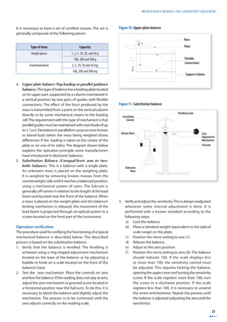
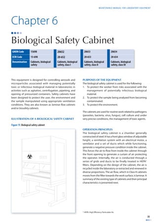
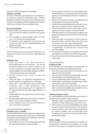
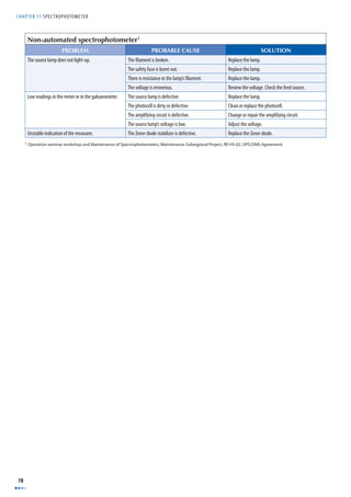
Type of cabinet, with illustration Characteristics
CLASS II — TYPE B1
1. Protection provided: to the operator, the product and
the environment.
2. Air velocity entering the cabinet: 50.8 cm/s.
3. Suitable for working with agents with biosafety level
1, 2 or 3.
4. Filtration system: Two HEPA fi lters. It extracts
potentially contaminated air (70 %) through a duct
and recycles inside of the cabinet, after fi ltering, air
taken from the exterior, through the front grid (30 %).
5. All biologically contaminated ducts have a negative
pressure.
6. Allows work with small quantities of toxic and
radioactive chemicals.
CLASS II — TYPE B2
1. Protection provided: to the operator, the product and
the environment.
2. Air velocity on entering the cabinet 50.8 cm/s.
3. Suitable for working with agents of biosafety level 1, 2
or 3.
4. Filtration system: Two HEPA fi lters. It is known as the
total extraction cabinet. It does not have any type of
recirculation.
5. All biologically contaminated ducts have a negative
pressure.
6. It has an extraction duct which allows work with toxic
and radioactive chemicals.
Plenum System
Exyraction Duct
HEPA Filters
Laminar Flow
Work Surface
V=100 PLm
[50.8cm/s]
Prefilter
Extraction Duct
HEPA
Extraction Filter
Posterior Duct with
Negative Pressure
Back Grid
Front Grid
Lateral View
HEPA
Supply Filter
V vert = 55 PLm - (28cm/s)
V = 100 PLm - (50.8cm/s)](https://image.slidesharecdn.com/b2df9d01-141207144322-conversion-gate01/85/B2-df9d01-50-320.jpg)
![CHAPTER 6 BIOLOGICAL SAFET Y CABINET
38
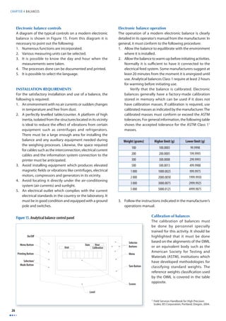
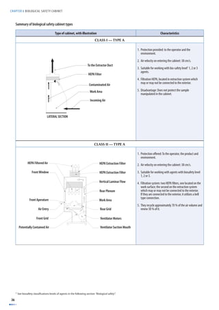
Type of cabinet, with illustration Characteristics
CLASS II — TYPE B3 OR A/B3
1. Protection provided: to the operator, the product and
the environment.
2. Air velocity on entering the cabinet: 50.8 cm/s.
3. Suitable for working with agents of biosafety level 1, 2
or 3.
4. Filtration system: Two HEPA fi lters.
5. All biologically contaminated ducts have a negative
pressure.
6. It is known as a combined cabin. It can be connected
by means of a duct. It is denominated as Type B3. If the
duct is missing, it is a Type A. It recycles 70 % of the air
volume inside the cabinet.
CLASS III
1. Protection provided: to the operator, the product and
the environment.
2. Filtration system: two HEPA fi lters in series in the
extraction; a HEPA fi lter in the admission.
3. Suitable for working with agents classifi ed biosafety
level 4.
4. Totally sealed cabinet. The intake and extraction
elements are conducted through a double -door pass-through
box. The manipulation of materials is done by
using sealed gloves at the front of the cabinet.
HEPA Extraction Filter
HEPA Supply Filter
V vert = 55 PLm (28cm/s)
V = 100 PLm - (50.8cm/s)
Front Grid
Rear Duct with Pressure [-]
Rear Grid
LATERAL VIEW](https://image.slidesharecdn.com/b2df9d01-141207144322-conversion-gate01/85/B2-df9d01-51-320.jpg)
![CHAPTER 6 BIOLOGICAL SAFET Y CABINET
44
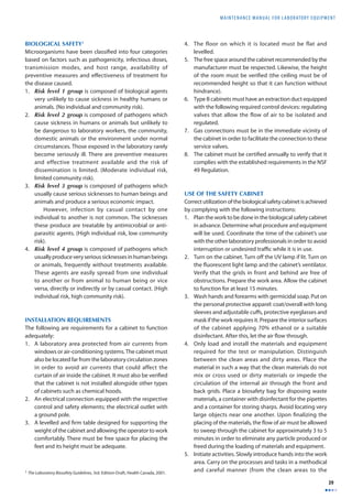
BASIC DEFINITIONS
Aerosol. A suspension of fi ne solid or liquid particles in the air. Their average diameter ranges between 10-4 and 10-7 cm.
Air supply. Air which enters the cabinet through the front or work opening and replaces the air extracted from the cabinet.
Biological Safety cabinet. Equipment with appropriate ventilation conditions protecting the user, the environment and the sample from aerosols and microparticles,
associated with the management of potentially infectious biological material in laboratories as a result of activities such as agitation, centrifugation, use of pipettes
and opening of pressurized containers.
Certifi cation. Procedure establishing that the biological safety cabinet’s functioning complies with criteria and minimum requirements to operate safely. Standard
NSF 49 applies to the Class II cabins, Type A, B1, B2 and B3.
Decontamination. Removal or destruction of infectious agents; removal or neutralization of toxic agents.
HEPA fi lter. A fi lter with the ability to remove particles with average diameters of 0.3 μm with 99.97 % effi ciency. These fi lters are constructed of Boron silicate
micro fi bres bonded together with a water resistant adhesive. The fi ltering material is folded inside of a frame with the aim of increasing the fi ltration area.
Laminar fl ow. Non-turbulent fl ow of a viscous fl uid (e.g. air) in layers near a boundary. It occurs when Reynolds number [Re] is less than 3000.
NSF. An acronym of the National Sanitation Foundation, a non-profi t organization dedicated to research, education and service, which seeks to resolve problems
related to human beings, promote health and enrichment of the quality of life through conservation and improvement of the environment. NSF standards supply
the basic criteria for promoting salubrious conditions and public health protection.
Toxic. A substance with a physiologically adverse eff ect on the biological systems.
Ultraviolet light (UV). This is electromagnetic radiation, the wavelength of which is between 200 and 390 nm. It is used in biological safety cabinets for its
germicidal properties.
Work surface. A surface used when performing work, operation or activity inside the biological safety cabinet in this case.](https://image.slidesharecdn.com/b2df9d01-141207144322-conversion-gate01/85/B2-df9d01-57-320.jpg)
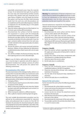
![MAINTENANCE MANUAL F O R LABORATORY EQUIPMENT
45
Chapter 7
Centrifuge
GMDN Code 15115 10778 10778
ECRI Code 15-115 15-117 15-116
Denomination Centrifuges, standing, low velocity,
non-refrigerated, for blood bank
Centrifuge, standing,
refrigerated
Standing centrifuge
The word centrifuge comes from the Latin word centrum
which means centre and fugere which means to escape. The
centrifuge is designed to use the centrifugal force generated
in rotational movements to separate the constitutive
elements of a mixture. There is a wide range of centrifuges
capable of serving specifi c industry and research needs. This
chapter focuses on standing centrifuges normally used in
public health and clinical laboratories.
PHOTOGRAPH OF CENTRIFUGE
PURPOSE OF THE CENTRIFUGE
The centrifuge uses centrifugal force (the force generated
when an object rotates around a single point), for separating
solids suspended in a liquid by sedimentation, or liquids of
diverse density. The rotational movements allow forces much
greater than gravity to be generated in controlled periods
of time. In the laboratory, centrifuges are generally used in
processes such as the separation of solid components from
biological liquids through sedimentation and in particular
of blood components: red cells, white cells, platelets among
others and for conducting multiple tests and treatments.
There are several kinds of centrifuges. The most widely used
in public health, surveillance and clinical laboratories are the
table-top centrifuge, the ultracentrifuge, the haeamatocrit
centrifuge and the standing centrifuge.
OPERATION PRINCIPLES
Centrifuges represent a practical application of Newton’s
law of motion. When a body of mass [m] turns around
a central point [O], it is subjected to a centripetal force
[N] directed towards the rotation axis with a magnitude
N = mω2R, where [m] is the mass of the body, [R] is the radius
and ω is the angular speed. Centrifuges possess a rotating
axis on which is mounted a rotor with sample receiving
compartments. Tangential speed is defi ned by the following
equation: VT=ωR.
Photo courtesy of Beckman Coulter](https://image.slidesharecdn.com/b2df9d01-141207144322-conversion-gate01/85/B2-df9d01-58-320.jpg)
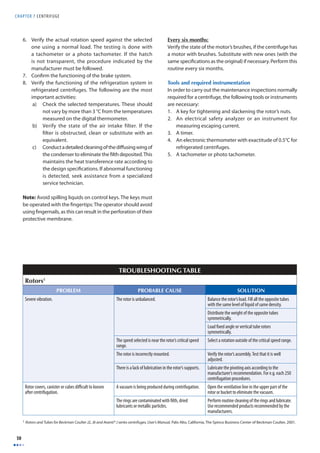
![CHAPTER 7 CENTRIFUGE
46
When the system spins at a speed of ω radians per second,
the samples are subjected to the centrifugal force Fp of the
same magnitude as N, but in an opposite direction. The
fi gure shown below1 features a diagram of the concept,
of its actual application and of the obtained result. This
Fp force acts on particles in the substance centrifuged,
causing them to separate as a result of diff erences in density.
Denser particles will settle at the bottom of the tube in
shorter periods of time, while lighter ones require longer
periods of time, settling onto those of greater density. The
relationship between the centrifugal acceleration [ω2r ] to a
given radius [r] and the force of gravity [g] is known as the
relative centrifugal fi eld or [RCF]2.
RCF = rω2
g
The RCF is the tool which allows rotors of different
specifi cations to be compared when equivalent centrifugal
eff ects are required.
COMPONENTS OF THE CENTRIFUGE
The most important components of a centrifuge are the
following3:
The electric/electronic control which generally has the
following elements:
1. On and off control, operation time control (timer),
rotation speed control (in some centrifuges), temperature
control (in refrigerated centrifuges), vibration control
(safety mechanism) and brake system.
2. Refrigeration system (in refrigerated centrifuges).
3. Vacuum system (in ultracentrifuges, not shown in the
fi gure).
4. Base
5. Lid/cover
6. Casing
7. Electric motor
8. Rotor. There are different types of rotors. The most
common are the fi xed angle, the swinging buckets, the
vertical tube and the almost vertical tube types, which
are explained next.
Sectional diagram of a centrifuge (numbers correspond to
descriptions in the text above)
1 Newton’s law of movement, together with the explanation of the inertia
marks of reference can be consulted in books on physics, chapters on
uniform circular movement.
2 RCF. Relative Centrifugal Field.
3 The numbers identifying each component correspond to those in the
sectional diagram of the centrifuge.
Figure 20. Centrifugal force concept](https://image.slidesharecdn.com/b2df9d01-141207144322-conversion-gate01/85/B2-df9d01-59-320.jpg)
![MAINTENANCE MANUAL F O R LABORATORY EQUIPMENT
47
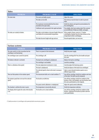
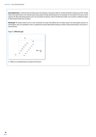
Types of rotors
Centrifuges use many diff erent types of rotors. Among the
most commonly used are the following:
Type of rotor Characteristics Transversal cross-section
Fixed angle rotors. These are general purpose rotors. They keep tubes at a fi xed
angle [α] which by design, is specifi ed between 20 and 45
degrees. They are used for sediment sub-cellular particles.
The angle shortens the trajectory of the particles and the
centrifugation time compared to the swinging buckets
rotors.
Swinging buckets rotors. These are used for carrying out isopycnic studies (separation
by density) and rate-zonal studies (separation by
sedimentation coeffi cient), where maximum resolution of
the zones is required for the sample.
Vertical tube rotors. This type of rotor keeps tubes parallel to the rotational axis.
Thus, separate bands are formed across the tube’s diameter,
not its length. These rotors are used for carrying out
isopycnic studies and in some cases, zonal limit separations
where a short centrifugation time is important. These rotors
use specially designed tubes.
Almost vertical tube rotors. This type of rotor is designed for gradient centrifugation
when some sample components do not participate in
the gradient. The small angle of these rotors reduces the
centrifugation time in comparison to fi xed angle rotors.
_
Position in
Rotation
Position
at Rest
r](https://image.slidesharecdn.com/b2df9d01-141207144322-conversion-gate01/85/B2-df9d01-60-320.jpg)
![MAINTENANCE MANUAL F O R LABORATORY EQUIPMENT
49
6. Obey the recommendation related to reducing the
operation speed when working with high density
solutions in stainless steel tubes or plastic adaptors.
Manufacturers provide the related information.
7. Use titanium rotors if working with saline solutions
frequently.
8. Protect the rotors’ coating in order to avoid the metal
base from deteriorating. Do not use alkaline detergents
or cleaning solutions which can remove the protective
fi lm. The rotors generally made of aluminium [Al] are
covered by a fi lm of anodized aluminium which protects
their metal structure.
9. Use plastic brushes when cleaning the rotor. Metal
brushes scratch the protective coating and generate
sources for future corrosion. Corrosion is accelerated
in operation conditions and shortens the rotor’s
operational life.
10. If there are spills of corrosive substances, wash the rotor
immediately.
11. Air dry the rotor once cleaned and washed with water.
12. Store vertical tube rotors and almost vertical tube rotors
with the larger side facing downwards and without their
covers.
13. Store rotors in a dry area. Avoid leaving them in the
centrifuge.
14. Store swinging buckets rotors without the compartments’
covers.
15. Lubricate spiral and O-rings, according to the
manufacturer’s recommendation.
16. Observe recommendations related to guaranteed times
and operational life of each type of rotor.
17. Avoid using rotors whose operational lives have
ended.
18. Use a shield if working with radioactive material.
19. Load or unload rotors inside a biological safety cabinet
if working with materials classifi ed as Biosafety level II
or higher.
20. Never try to open the cover of a centrifuge while it is
functioning and never try to stop the rotor by hand.
Tubes
Tube care includes aspects such as fi lling of the tubes,
adequate temperature selection, centrifugation speed
limitations, washing and sterilization. The principle
recommendations are the following:
1. Wash tubes, adaptors and other accessories by hand
using a 1:10 mild detergent solution in water and a soft
textured brush (not metallic). Avoid using automatic
dishwashers.
2. Avoid using alcohol and acetone since such liquids aff ect
the structure of the tubes. Manufacturers recommend
the solvent to be used with each type of centrifugation
tube material.
3. Avoid drying tubes in a drying oven. Dry always with a
stream of hot air.
4. Verify if the tubes are reusable or not. If they are
disposable, use them only once.
5. For sterilizing, it is necessary to verify the material from
which the tube is made, as not all can stand sterilization
by heat. Glass tubes are normally sterilized with vapour
at 121 °C for 30 minutes.
6. Store tubes and bottles in a dark, fresh, dry place,
far from chemical vapours or ultraviolet radiation
sources.
7. Verify maximum fi lling levels and the sealing of thin
wall tubes in order to avoid collapse inside the rotor
by the action of the centrifugal force. Comply with
manufacturers recommendations.
Preventive maintenance
Warning: Never carry out a technical intervention in a
centrifuge if it has not been previously decontaminated.
The most important maintenance routines performed on a
centrifuge are the following:
Frequency: Monthly
1. Verify that the centrifuge external components are free
of dust and stains. Avoid aff ecting the rotor with spills.
Clean the rotor compartment using a mild detergent.
2. Test that the rotors’ connecting and adjustment
mechanisms are in good condition. Keep the points
lubricated as the manufacturer recommends.
3. Verify the locking /safety mechanism of the centrifuge’s
cover. This is fundamental in guaranteeing operators’
safety as this mechanism keeps the cover of the
centrifuge closed while the rotor is turning.
4. Check the lubrication state of elements such as for
O-rings as the manufacturer recommends. Always use
lubricants according to the manufacturer’s instructions
(frequency and type of lubricants). In recently
manufactured centrifuges, there are sealed ball bearings
which do not require lubrication.
5. Verify the state of gaskets and watertight joints.
Frequency: Annually
1. Verify that electronic cards are clean and well connected.
2. Test operation controls needed for selection of the
diff erent parameters of the centrifuge: speed, time,
temperature, alarms selectors and analogous or digital
instruments.
3. Verify compliance with electrical standards. Use an
electric safety analyzer: earth resistance test, escaping
current test.
4. If the centrifuge is refrigerated, test the temperature by
using an electronic thermometer. The temperature must
not vary by more than ± 3 °C.
5. Examine the exactitude of the time controls. Use a timer.
The time measured must not vary by more than ± 10 %
of the programmed time.](https://image.slidesharecdn.com/b2df9d01-141207144322-conversion-gate01/85/B2-df9d01-62-320.jpg)
![CHAPTER 7 CENTRIFUGE
52
BASIC DEFINITIONS
Anodized coating. A hard, thin layer of aluminium oxide, which is deposited on the surface of a rotor by means of electrochemical processes with the aim of
preventing corrosion. The coating is often fi nished in various colours.
Angular speed. The turning rate of a body measured in radians per second. It is calculated using the following formula:
ω = 2π ×rpm
60
Where:
rpm = revolutions per minute
π = constant with a value of 3.1416
Brush. A device that transmits electrical energy between the external electrical connection (cables in a static state) and the internal components (in rotation) of a
motor. In general, brushes are manufactured in very soft textured graphite and, in motors, must be changed regularly (every six months).
Centrifugal force. Apparent force equal and opposite to the centripetal force, driving a rotating body away from the centre of rotation and caused by the inertia of
the body. It is one of the components of the inertia vector, which equals the set of forces acting on a body. Its magnitude is always [m x an] and its direction radial,
moving away from the centre.
Density. A body’s mass by volume unit, generally expressed in gram per cm3.
D = m
V
Isopycnic separation. A method for separating particles based on the density of the particle’s fl otation. It is known as sedimentation in balance. The speed of a
particle due to diff erences in density is given in the formula:
v =
d2 ρp − ρc ( )
18μ
⎛
⎝
⎜⎜
⎞
⎠
⎟⎟ × g
Where:
v = speed of sedimentation
dr
dt
⎛
⎜
⎝
⎞
⎟
⎠
d = diameter of the particle
ρp = density of the particle
ρc = density of the solution
μ = viscosity of the liquid medium
g = gravitational force
Radian. A unit of angular measure equal to the angle subtended at the centre of a circle by an arc equal in length to the radius of the circle. It is expressed as the
ratio between the arc formed by the angle with its vertex in the centre of the circle, and the radius of that circle.
RCF (Relative centrifugal fi eld or force). A relationship between the centrifugal acceleration and a specifi c speed and radius, [rω2] given with the normal gravity
acceleration. It is calculated by means of the following equation:
RCF = rω2
g
Where:
R = radius in mm
ω= angular speed in radians per second
ω = 2π ×rpm
60
g = Standard gravity acceleration = 9 807 mm/s2
Resonance. A situation in which a mechanical system vibrates as a response to a force applied at the system’s natural frequency.
Sedimentation. Particles from a suspension settling at the bottom of the liquid as a result of the action of the gravitational force. During centrifugation, this process
is accelerated and particles move away from the rotational axis.](https://image.slidesharecdn.com/b2df9d01-141207144322-conversion-gate01/85/B2-df9d01-65-320.jpg)
![MAINTENANCE MANUAL F O R LABORATORY EQUIPMENT
57
BASIC DEFINITIONS
Distillation. A process through which a fl uid in liquid phase is heated until converted into vapour and then cooled and condensed back into liquid phase. The
distillation process is used for separating mixed substances, taking advantage of their diff erence in volatility. To obtain very pure substances, consecutive distillation
cycles are performed with the aim of progressively eliminating other substances present in the mix.
Hardness (of water). A chemical characteristic of water determined by the carbonate, bicarbonate, chlorine, sulphate and occasionally calcium nitrate and
magnesium content. The resulting resistance is undesirable in some processes. There are two types of resistors in water.
• Temporary hardness. This is determined by the magnesium and calcium carbonate and bicarbonate content. It may be eliminated by boiling the water and
subsequently fi ltering out the precipitate. It is also known as carbonate resistance.
• Permanent hardness. This is determined by all the calcium and magnesium salts, except the carbonates and bicarbonates. It cannot be eliminated by the
boiling of water and it is also known as non-bicarbonate resistance.
Interpretation of resistance:
Resistance as CaCO3 interpretation
0–75 soft water
75–150 water with little resistance
150–300 resistant water
> 300 water with great resistance
In potable water, the maximum limit allowed is 300 mg /l.
In water for heaters, the limit is 0 mg / l.
• Calcium resistance or hardness (RCa++). Quantity of calcium present in water.
• Magnesium resistance or hardness (RMg++). Quantity of magnesium present in water.
• Total resistance or general hardness [TH]. Quantity in calcium [Ca] solution and magnesium [Mg] as cations, without taking into account the nature of the
anions present in the water. It is expressed as ppm (parts per million) of calcium carbonate (CaCo3).
Incrustation (scale). A name given to solids in suspension deposited in layers on the surface of water storage containers.
Solution. A homogenous mix of two or more substances characterized by the absence of chemical reactions between the components of the liquid mixture. The
liquid component which generally appears in greater proportion is called the solvent and that found in a lesser quantity in solution, the solute.](https://image.slidesharecdn.com/b2df9d01-141207144322-conversion-gate01/85/B2-df9d01-70-320.jpg)

![CHAPTER 9 D I LUTOR
64
BASIC DEFINITIONS
Cavitations. A phenomenon in fl uids when a vacuum is created upon emptying a vessel. The pressure decreases until it reaches the vapour pressure of the fl uid.
This produces diverse phenomena such as vaporization of gases dissolved in the liquid or, in the case of water, the formation of vapour bubbles collapsing after an
infi nitesimal time lapse, perforating the surfaces of conducts in the immediate vicinity. This occurs in dilutors when using large capacity syringes with elevated
propulsion speed.
Concentration. A quantity measurement of a chemical substance present in a solution. The concept is expressed as the quantity of a substance dissolved into a
solvent. Concentration is expressed in diverse forms; the most common are: molarity [M], molality [m], normality [N], percentage rate of solute.
Dilution. To reduce the concentration of a solution by adding other fl uids. The fl uid added is known as the diluent. Adding the molecules of a liquid substance with
the molecules of another liquid substance. In order to determine the volume V1 of liquid needed to obtain V2 volume at a concentration C2 from a stock solution of
concentration C1, the following equation is used:
V1 = V2C2
C1
Dispenser. A device used for distributing liquids.
Dispensing. Distributing a fl uid at a constant volume or in a progressive form.
Dissolution. Process by which a chemical in solid form is dissolved in a solvent (e.g. water or other liquid). The chemical now in solution is called the solute.
Equivalent – gram [Eq]. Mass in grams of solute divided by its equivalent weight [EW]:
Eq = mass(g)
EW (g)
Equivalent weight [EW] (of one substance). Results from dividing the molecular weight [MW] by its valency.
EW = MW (g)
valency
Molality [m]. Number of moles of a given substance, for every 1000 g of solvent. Thus an m molal solution is obtained by adding m moles of the substance to
1000 g of water.
Molarity [M] (of a solution component). Number of moles of solute for each litre of fi nal solution. A solution n Molar of a salt is obtained by adding n moles from
that salt to water until obtaining one (1) litre of solution. Normally, the formula employed is the following:
M = moles
Vol(L)
Mole. Molecular weight (MW) of the solute expressed in grams:
moles= mass(g)
EW
Normality [N] (of a solute). Number of moles of solute per litre of fi nal solution.
N = Eq
Vol(L)
Solution. A homogeneous liquid mixture of two or more substances. The dissolved chemical(s) called the solute(s) usually name the solution. The substance in
which the solute(s) are now dissolved is called the solvent. There is a usually greater quantity of solvent than solute(s) in a solution.
Weight/Volume. Relationship in clinical biochemistry expressing the mass of the solution in grams or its submultiples per volume unit in litres or submultiples
of a litre. For example: g/l, mg/ml.
Note: Another type of notation known as “part per unit” is used for measuring extremely low concentrations. For example: parts per million (ppm) means that there
is a particle of a given substance for each 999 999 particles of other substances.](https://image.slidesharecdn.com/b2df9d01-141207144322-conversion-gate01/85/B2-df9d01-77-320.jpg)
![MAINTENANCE MANUAL F O R LABORATORY EQUIPMENT
69
Chapter 11
Spectrophotometer
GMDN Code 36411 36411 36411
ECRI Code 15-082 15-083 15-084
Denomination Spectrophotometer,
The word spectrophotometer is derived from the Latin word
spectrum, which means image, and the Greek word phos
or photos, which means light. The spectrophotometer
is one of the main diagnostic and research instruments
developed. It uses the properties of light and its interaction
with other substances. Generally, light from a lamp with
special characteristics is guided through a device, which
selects and separates a determined wave length and makes
it pass through a sample. The light intensity leaving the
sample is captured and compared with that which passed
through the sample. Transmittance, which depends on
factors such as the substance concentration is calculated
from this intensity ratio.
PURPOSE OF THE EQUIPMENT
The spectrophotometer is used in the laboratory for
determining the presence or concentration of a substance
in a solution, thus allowing a qualitative or quantitative
analysis of the sample.
OPERATION PRINCIPLES
As a basic principle, light is considered to be a form of
electromagnetic energy. In space, it has a constant and
universal velocity [C] of approximately 3 x 10⁸ m/s. In any
other medium (transparent) through which light passes, its
velocity will be slightly lower and can be calculated by the
following equation:
v0 = C
n
Where:
v0= Velocity at which light passes through the medium
n = Medium refraction index: whose value oscillates, in
general, between 1.0 and 2.5.
ultraviolet
Spectrophotometer,
ultraviolet, visible
Spectrophotometer,
visible
Photo courtesy of Beckman Coulter
PHOTOGRAPH OF SPECTROPHOTOMETER
Conventional spectrophotometer](https://image.slidesharecdn.com/b2df9d01-141207144322-conversion-gate01/85/B2-df9d01-82-320.jpg)
![CHAPTER 11 SPECTROPHOTOMETER
70
The electromagnetic energy has a very wide range of
wavelengths. Some examples are shown in the following
table:
Upon passing or interacting with diverse mediums,
light undergoes a series of phenomena. Among these
are featured refl ection, refraction, diff raction, absorption,
diff usion, polarization and other phenomena measured by
various instruments and devices. The table below shows the
wavelength ranges used for carrying out spectrophotometry
tests.
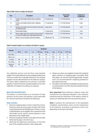
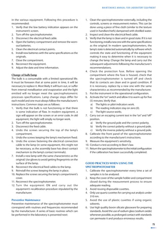
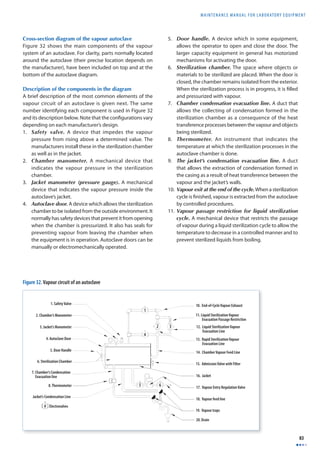
With regard to the interaction of light with matter, Figure
27 assists in clarifying the complexity of phenomena that
occur.
The diagram in Figure 27 shows that the incidental radiation
[Io] can undergo a series of transformations. It can be
refl ected [Ir], transmitted [It], diff used [Id], absorbed and
directly emitted as fl uorescence [If ]. The phenomena on
which spectrophotometry is based are mainly absorption
and transmission. In order to understand how, it is necessary
to take Beer Lambert’s law into account.
Beer Lambert’s Law. Also known as Beer’s law or Beer
Lambert Bouguer’s law, it identifi es the relationship between
the concentration of the sample and the intensity of light
transmitted through it. With regard to the law mentioned,
there are two implicit concepts: transmittance [T] and
absorbance [A].
The transmittance [T] is the fraction of the incidental light of
determined wavelength passing through the sample.
Where:
It = intensity of the transmitted radiation
Io = intensity of the incidental radiation
Type of electromagnetic
energy Range of wavelength
Radio waves From a few meters to a few kilometres
Radar waves From 1 to 10 cm
Infrared waves From 1 to 10 microns (10-6 m)
Visible light From 300 to 700 nm (nanometres)
X rays From 0.1 to 0.5 Å (Angstrom)
Gamma rays Approximately 0.0012 Å (Angstrom)
Section of the lighting
spectrum Range of wavelength
Ultraviolet 10–200 nm (nanometres)
Near ultraviolet 200–280 nm
Visible light 380–780 nm
Near infrared 780–3 000 nm
Mid infrared 3 000–20 000 nm
Far infrared 30 000–300 000 nm
T = I t
I o
Absorbed Radiation
Incidental
Radiation (Io)
Reflected
Radiation (Ir)
Transmitted
Radiation (It)
Diffused
Radiation (Id)
Fluorescence(If)
Figure 27. Interaction of light with matter](https://image.slidesharecdn.com/b2df9d01-141207144322-conversion-gate01/85/B2-df9d01-83-320.jpg)
![MAINTENANCE MANUAL F O R LABORATORY EQUIPMENT
71
The percentage of transmittance [%T] can be expressed by
the following equation:
The concentration of light absorbing molecules in a sample
is proportional to the absorbance [A] of that sample. It is
expressed mathematically as:
Where:
A = Absorbance measured
ε = Molecule absorbance coeffi cient
[litres/moles/cm]
l = Distance of the trajectory traversed (path length)
by the light in the sample
c = Sample concentration [moles/litres]
Absorbance [A] is related to transmittance [T] through the
following equation:
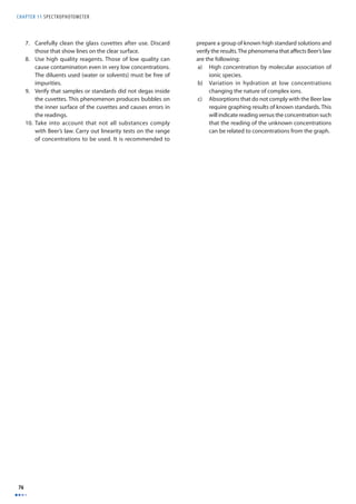
The following diagram explains the phenomenon of
absorbance:
The graphs presented next demonstrate how absorbance [A]
and transmittance [T] vary as a function of the concentration
[C] according to Beer Lambert’s law.
Concentration
Absorbance graph
In conclusion it can be inferred that by increasing the
concentration of a substance, the transmittance is decreased
and, upon increasing the concentration of the substance,
absorbance is increased.
The linearity of Beer Lambert’s law is aff ected if the following
conditions occur.
1. Displacement of the sample’s chemical balance as a
function of the concentration.
2. Deviations in the absorbance coefficients, greater
concentrations than 0.01 M due to electrostatic
interaction between nearby molecules.
3. Changes in the refraction index at high concentrations
of the analyte.
4. Diff usion of light due to particles in the sample.
5. Fluorescence or phosphorescence of the sample.
6. Non-monochromatic radiation.
%T = I t
I o
×100
A =ε × l × c
A = log10
1
T
= log10
I o
I t
= log1010ε×c×l =ε ×c × l
Figure 28. Absorbance phenomenon
Incidental Light
lo
Transmitted Light
lt = lo x 10 -a(Q)*c*l
Pathlength
Absorbing Solution of
Concentration [C]
Moles/Litre
Concentration
Transmittance
A = Log 1T
Transmittance graph
A = cxx l x c
Absorbance](https://image.slidesharecdn.com/b2df9d01-141207144322-conversion-gate01/85/B2-df9d01-84-320.jpg)
![MAINTENANCE MANUAL F O R LABORATORY EQUIPMENT
79
BASIC DEFINITIONS
Absorption. A physical phenomenon occurring when atoms or molecules of a substance absorb light (photons). The energy of a photon is taken up by another entity,
e.g. by an atom whose valence electrons change between two electronic energy levels destroying the photon in the process. The energy absorbed is lost through
heat or radiation. Absorbance is a mathematical measure of absorption, expressed in optical density units (OD).
Angstrom. A unit of length equal to 10-10m. Its symbol is [Å]. It is used for carrying out measurements of X- or Gamma-rays.
Band width. A wavelength range that a monochromator can transmit.
Diff raction. Phenomenon caused by a change in the directions and intensities of a group of waves after reaching an obstacle, or through a narrow aperture whose
size is approximately the same as the wavelength of the waves.
Diff raction grating. A component of the monochromator, also called “transmission grating”. It diff racts light and is shaped as a series of parallel fi ssures carved
onto a refl ecting surface. It is made by tracer machines protected against vibrations and temperature variations. Gratings used in spectrophotometers are copies of
one master grating that usually has more than 1200 fi ssures per millimetre. Figure 31 demonstrates the phenomenon of diff raction.
If the refl ection angle [δ] is known as well as the width [d] of the fi ssures, the wavelength [λ] can be determined according to the following equation:
sinδ = nλ
d
Intensity [IV]. The amount of light emitted by a source in a particular direction per unit of time. More generally, a measurement of the average energy fl ow per
unit of time. To get the intensity, the energy per unit of volume is multiplied by the speed at which the energy moves. The resulting vector is the energy by square
surface per unit of time.
Molar extinction or absorptivity coeffi cient [ε]. Measures how strongly a chemical species absorbs light at a determined wavelength. It is an intrinsic property
of the chemical species. When there is more than one absorbing species in a solution, the absorbance is the sum of the absorbance values for each individual species.
The absorbance at a given wavelength of a mixture of species X, Y ... is given by
A = ∫ [Cx ×εx + Cy ×εy + ...]
Where A is the absorbance of the mixture.
Nanometre. A unit of length corresponding to 10-9 m (a thousand millionth of a metre). It is identifi ed by the symbol [nm]. It is used for measuring visible or
ultraviolet light wavelengths.
Path length. The distance covered by visible or ultraviolet light through a sample in an analytical cell (cuvette or well).
Refraction. A change of direction that occurs when a ray of light reaches the interface between two media.
The light cuts at an angle [a] and refracts at an angle [b] upon changing propagation medium.
Figure 30. Refraction of light](https://image.slidesharecdn.com/b2df9d01-141207144322-conversion-gate01/85/B2-df9d01-92-320.jpg)
![Maintenance manual for laboratory equipment
81
Chapter 12
Autoclave
GMDN Code 35366 35366 35366
ECRI Code 13-746 16-141 16-142
Denomination Sterilizing unit,
The autoclave is a piece of equipment used for sterilizing.
The word sterilizing means the destruction or elimination
of all forms of life (microbial, including spores) present
in inanimate objects by means of physical, chemical or
gaseous procedures. The word sterilizer comes from the
Latin word sterilis which means not to bear fruit. This chapter
will focus exclusively on autoclaves as these are greatly
used in public health establishments, clinical and research
laboratories. This type of equipment is also known as a
sterilizer. Sterilization must be considered as a group of
very important interrelated processes for carrying out
health services, (sterilization of materials, culture medium,
instruments) within rigorous conditions of asepsis. The
processes associated in achieving sterile conditions of
inanimate objects are the following:
1. Cleaning
2. Decontamination
3. Inspection
4. Preparation and packing
5. Sterilization
6. Storage
7. Delivery of materials
PURPOSE OF THE AUTOCLAVE
The autoclave is equipment designed with the aim of reliably
eliminating1 microorganisms, which would otherwise
be present on objects used in diagnostic activities, in
treatment or surveillance in health institutions (hospitals,
laboratories). It is also widely used in the food processing
and pharmaceutical industries. In the laboratory, materials
and objects are sterilized for the following purposes:
1. To prepare materials for bacteriological cell cultures
(test tubes, pipettes, Petri dishes, etc.) in order to avoid
their contamination.
2. Prepare elements used for taking samples. (All must be
in sterile conditions: needles, tubes, containers).
3. Sterilize contaminated material.
Autoclaves are available in many sizes. The smallest are
the table-top type and the largest are complex equipment
that require a great amount of pre-installation for their
operation. The volume of the sterilization chamber is taken
as a reference and measured in cubic decimetres [dm3] or in
litres [l] in order to measure the autoclave’s size. Depending
on how their operation is controlled, it is possible to find
manual, semiautomatic or fully automatic models.
1 The Food and Drug Administration (FDA) classifies sterility of an article
based on statistical studies. An article is considered sterile if the probability
of encountering it not sterile in a set of articles submitted to the same
process of sterilization, is less than one in a million. This index is called
Sterility Assurance Level (SAL) and describes the theoretic potential of
microbial inactivation in a sterilization process.
steam
Sterilizing unit, bulk Sterilizing unit,
tabletop
Photo courtesy of Systec GmbH
PHOTOGRAPH OF autoclave](https://image.slidesharecdn.com/b2df9d01-141207144322-conversion-gate01/85/B2-df9d01-94-320.jpg)
![CHAPTER 12 AUTOCLA VES
82
OPERATION PRINCIPLES
Autoclaves work by taking advantage of the thermodynamic
properties of water which can be considered as a pure
substance. In normal conditions (at sea level and pressure
of 1 atmosphere) water (in liquid phase) boils and is
converted into vapour (gaseous phase) at a 100 °C. If the
pressure is reduced, it boils at a lower temperature. If the
pressure rises, it boils at a greater temperature. Through
the control of water vapour pressure, the autoclave can,
in its sealed chamber, reach temperatures higher than 100
°C; or inversely, by controlling the temperature, can achieve
pressures greater than atmospheric pressure. The following
graph demonstrates the behaviour of water depending on
conditions of pressure and temperature.
Autoclaves use pressurized saturated vapour (with a quality
greater than 98%) for transmitting thermal energy to
elements that require sterilization. In general, this method
is known by the terms steam or moist heat sterilization. This is
the sterilization method mostly used due to its effectiveness,
rapidity and low cost. However, not all materials can be
sterilized with moist heat; for those elements that are
affected by heat and humidity, alternative methods of
sterilization have been developed. In the laboratory, in order
to carry out sterilization processes, steam autoclaves as well
as drying ovens using dry heat (without the presence of
humidity) are used. See Chapter 13: Drying ovens.
Temperature / Volume Graphic Pressure / Temperature Graphic
Temperature
P3
P2
Saturated
Vapour Line
D
Volume
P1
Critical
Point
B C
Saturated
Liquid Line
A
1. This graph shows two defined lines: the saturated liquid (to the left) and the
saturated vapour (to the right) lines.
Pressure
Fusion Line
Liquid Phase
H H’
Solid
Phase
Critical Point
Vaporization Line
Vapour Phase
G G’
E E’
Sublimation line
Temperature
1. This graph shows the behaviour and relation between the solid, liquid and
gaseous phases of water depending on the pressure and temperature conditions.
2. As the pressure increases, so does the temperature. (See lines P1, P2, P3)
where:
P3 > P2 > P1.
2. The sublimation lines show that at determined conditions, if heat is
transferred to the solid phase, it can be converted directly into the vapour phase
(section E-E), without going through the liquid phase.
3. To the left of the saturated liquid line, the water is in a liquid state (plot A-B).
Upon heat transfer, the temperature of the liquid is raised from Temperature A
to B.
3. The fusion line shows that at determined conditions, upon transferring heat
to water, the solid phase is transformed into the liquid phase and, if more heat is
added, it is transformed to the vapour phase (section H-H’).
4. Between the line of saturated liquid and saturated vapour (section B-C) there
is a mixture of the vapour and liquid phases, and the temperature remains
constant. The closer it is to point C, the greater is the vapour’s quality1.
4. The vaporization line shows at which temperature conditions the water in
liquid phase is transformed into the vapour phase.
5. To the right of the saturated vapour line, all the water is in vapour phase
(section C-D).
5. The point at which the three lines are intercepted is called the Triple Point. In
such circumstances the three phases exist simultaneously in equilibrium.
1 Quality [X]. The relationship between total vapour mass and total mass (liquid mass plus vapour mass). Quality = 1: means that the vapour is saturated and that
any increase in temperature will overheat the vapour.](https://image.slidesharecdn.com/b2df9d01-141207144322-conversion-gate01/85/B2-df9d01-95-320.jpg)
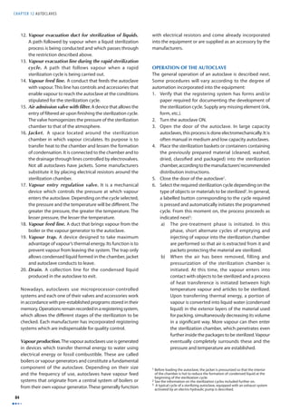
![CHAPTER 12 AUTOCLAVES
90
MAINTENANCE OF SPECIALIZED COMPONENTS
Included next are some specialized routines requiring
a service technician and applicable to equipment
components. Given that autoclaves have multiple designs,
routines stipulated here are only applicable to certain
equipment models.
Maintenance of solenoid valves
1. Verify the sound made by the bobbins or solenoids
(humming). Excessive noise is a warning of overheating
due to abnormally high electric currents through the
solenoid. Current alternates rise when the impedance [Z]
of the circuit decreases. This occurs when the solenoid
is not adequately surrounded by a closed iron cover.
An air gap in the magnetic circuit can be caused by dirt
which prevents the protective cover from reaching its
fi nal position when the solenoid is energized. Carefully
clean the housing of the bobbin and its nucleus so that
the piston’s movement is not impeded by fi lth.
2. Replace the O-rings between the solenoid and the body
of the valve once these have been disassembled.
3. Before any disassembly, verify how the solenoid valve
is installed. Some possess clear installation indications
but others lack such information.
4. When dismounting a servo-assisted solenoid valve,
control the position of the orifi ces that put it in contact
with the work environment, so as to be able to re-assemble
the valve.
Cleaning of the vapour fi lter
Warning: Before disassembling the vapour fi lter, dissipate
the vapour pressure in the system.
1. Lift the cover.
2. Remove the mesh.
3. Clean carefully.
4. Reinstall the mesh.
5. Replace the cover.
Here are some of the most common problems. Given the
diversity of brands, models and available technology, it
is advisable that users follow instructions from the user
manual for the autoclave used.](https://image.slidesharecdn.com/b2df9d01-141207144322-conversion-gate01/85/B2-df9d01-103-320.jpg)
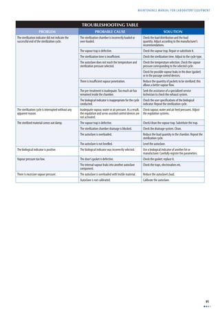
![CHAPTER 12 AUTOCLAVES
92
BASIC DEFINITIONS
Asepsis. A set of procedures necessary to eliminate microorganisms.
Atmosphere. An old unit of pressure equivalent to 101 325 Pa (Pascals) or to 14.69 pounds per square inch.
Bar. A unit of pressure equivalent to 105 Pa (Pascals).
Cleaning. Mechanical removal of all foreign material located on the surface of inanimate objects; in general, it implies the use of clean water combined with a
detergent. It is a basic procedure performed before submitting the objects to their respective sterilization processes. Cleaning can be done manually or by using
automatic methods. It must be understood that it is not a procedure destroying microorganisms, but only decreasing their quantity.
Decontamination. A procedure to decrease the quantity of microorganisms of an object or substance so that its use or/and manipulation is safe. For example,
objects used in patient care procedures in possible contact with fl uids, bodily substances or organic materials require decontamination or even sterilization (see
defi nition below).
Disinfection. A process that uses physical or chemical means to destroy any form of life in a vegetative state from inanimate objects (excluding spores).
Inspection. A visual evaluation of washed articles, with the purpose of fi nding defects or dirt that may interfere with the sterilization processes. It is a process of
great importance which may be done using a magnifying glass to discern minute details.
Jacket. Enclosed space around the sterilization chamber through which vapour circulates. Its function is to transfer heat to the sterilization chamber in the pre-treatment
stages (air removal) and post treatment (drying of the sterilized material).
Moist heat. A sterilization method that eliminates microorganisms by denaturation of the proteins which is accelerated by the presence of water vapour (steam).
Pascal (Pa). A unit of pressure from the International system, which corresponds to the force of a Newton (N) that acts on a (1) square meter:
Pa = 1N
m2
Quality. Thermodynamic property identifi ed in general with the letter [X] and defi ned as the relationship existing between the vapour mass and the total mass of
the substance under saturated conditions.
Servo-assisted valves. Solenoid-type valves that depend on the surrounding pressure to close or open. In general, these have membranes with small openings
through which the working medium is supplied.
Solenoid valves. Electromagnetic control devices used in multiple applications also known as electrovalves. The position of a piston is controlled by a bobbin which
is energized or at rest. The piston permits or impedes the passage of a fl uid inside of a determined circuit. They are used in hydraulic, pneumatic, vapour and vacuum
systems. Manufacturers have developed a great number of designs for specialized applications.
Sterilization. A set of actions by means of which all forms of life are destroyed (including spores) on inanimate objects using physical, chemical and gaseous
procedures.
Sterilization chamber. The area where objects requiring sterilization are placed. When the sterilization process is being carried out, the chamber is fi lled with
pressurized vapour, reaching temperatures directly related to the selected pressures. During the sterilization cycle, it is sealed by a door by a safeguarding system
which can only be opened once the sterilization process has been completed and the internal pressure has reached that of the atmosphere.
Sterilization indicator. A chemical or biological indicator that allows checking if an object or material has been submitted to a sterilization process successfully.
The most commonly known are the thermosensitive tape (it changes colour when the determined temperature conditions are reached) and B. stearothermophilus
spores.
Vapour trap. A device designed to restrict the passage of vapour and allow the passage of condensed liquid.](https://image.slidesharecdn.com/b2df9d01-141207144322-conversion-gate01/85/B2-df9d01-105-320.jpg)
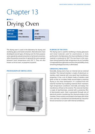
![CHAPTER 13 DRYING OVEN
94
The power (energy by a unit of time) dissipated by an
electrical resistor can be calculated by means of the
following equation:
Where:
I = Intensity of the electric current in amps [A]
R = electrical resistance in ohms [Ω]
Given that the energy is neither created nor destroyed but
transformed, it is possible to calculate the thermal energy
equivalent to the resistive elements. In the case of a resistive
wire, the quantity of heat [q] dissipated can be calculated
by the following equation1:
Where:
R = resistance of resistive wire
I = intensity of the electrical current
r0 = outer radius of the wire
L = length of the resistance wire
= is the heat generated per unit volume
Resistance [R] can be calculated by the following
equation:
Where:
ρ = resistivity of the resistor’s material
A = surface of the resistance wire
The oven has a metallic door with its own thermal insulation
equipped with a similarly insulated handle to prevent burns
on hands. The door is installed on the front part of the oven
by a set of hinges which allow it to open at a 180° angle.
The modern oven is controlled by a module with a microprocessor.
It allows selection of the equipment’s operation parameters and
its alarms; and the programming of cycles or thermal processes
through which are controlled, not only the temperatures but
also the way in which they need to vary in time through phases
of heating/cooling (natural) or through stable temperatures
maintained within certain time intervals. Ovens operate normally
from room temperature up to 350 °C. Some models have limited
ranges of operation. Older ovens simply have a set of resistors,
whose operation is controlled by a thermostat.
The following table features the temperature/time relationship
required for dry heat sterilization in drying ovens.
Table of temperature/sterilization time by dry heat
Temperature °C Time in minutes2
180 30
170 60
160 120
150 150
140 180
121 360
INSTALLATION REQUIREMENTS
In order to be used, the drying oven requires the
following:
1. A large, strong, levelled work table.
2. Free space of at least 5 cm around the oven and enough
space to place the material to be processed.
3. An electrical outlet with a ground pole of appropriate
size for supplying electrical power to the oven. It must
be in good condition and comply with the national
or international electrical standards used in the
laboratory and must not be more than 1 m away from
the equipment. The typical voltage used is 110 V or 220
V/60 Hz.
4. Verifying that the electrical circuit has the necessary
protection devices for guaranteeing an adequate
electrical feed.
OVEN OPERATION
A series of precautions must be taken into account for the
correct operation of the oven. Among the most important
are the following:
1. Do not use fl ammable or explosive materials in the
oven.
2. Avoid spills of acid solutions or corrosive vapours
inside the oven to prevent corrosion of the surfaces
and interior shelves.
3. Use personal protection elements (insulated gloves,
safety glasses and tongs for placing or removing
substances or materials inside the drying oven).
Operation routine
In general, the following procedure is performed:
1. Activate the main switch, pressing the button usually
identifi ed by the symbol [I].
2. Press the key identifi ed as Program.
1 This example of heat transference equation is for a wire-type resistor of
circular shape. For other shapes, diff erent equations must be used.
2 Time is counted from the moment that the corresponding temperature is
reached.
P = I 2R
I 2R = q˙ π r0
2L
q˙
R = ρ L
A](https://image.slidesharecdn.com/b2df9d01-141207144322-conversion-gate01/85/B2-df9d01-107-320.jpg)
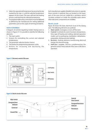
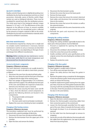
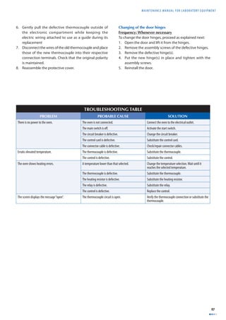
![CHAPTER 13 DRYING OVEN
98
BASIC DEFINITIONS
Circuit breaker. An electrical control device which allows a piece of equipment or a device to be ON or OFF. It is also called a switch.
Electric Thermocouple. A device used for accurate measurement of temperature. It consists of wirings of two diff erent metals joined together at one end, producing
a small voltage proportional to the diff erence in temperature between the two ends. This phenomenon is known as the “Seebeck eff ect” in honour of its discoverer,
the German physician Thomas Seebeck.
Heat. A form of energy transferred from one system at a given temperature to another at a lower temperature by means of the diff erence in temperature between
the two. When a system of great mass [M] is put in contact with another of small mass [m’] at a diff erent temperature, the resulting temperature is close to the initial
one of the greater mass system. It is said, then, that a quantity of heat ΔQ has been transferred from the system of higher temperature to that of lower temperature.
The quantity of heat ΔQ is proportional to the change in temperature ΔT. The proportion constant [C] or heat capacity of the system, allows the following relationship
to be established: ΔQ = CΔT, which infers that one of the consequences of the change in temperature in a system is heat transference.
Resistance. Opposition that a material or electrical circuit imposes to the fl ow of electric current. It is the property of a circuit that transforms electrical energy into
heat as it opposes the fl ow of current. The resistance [R], of a body of uniform section such as a wire, is directly proportional to the length [l] and inversely proportional
to the sectional area [a]. The resistance is calculated by the following equation:
R = k × l
a
Where:
k = constant that depends on the units employed
l = Length of the conductor
a = sectional area of the conductor
The ohm (Ω) is the common unit of electrical resistance; one ohm is equal to one volt per ampere.
Thermostat. A device which regulates the temperature of a system. It usually operates by expansion of one of its components which mechanically activates another
element, for example a switch which controls a particular function.](https://image.slidesharecdn.com/b2df9d01-141207144322-conversion-gate01/85/B2-df9d01-111-320.jpg)
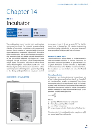
![CHAPTER 14 INCUBATOR
100
Thermal convection
In incubators with thermal convection, heat generated by
the system of resistors is transferred through air circulating
in the incubation chamber, transferring it to the samples.
The effi ciency of this process depends on air fl ow patterns.
In general, air enters from the bottom of the incubator
and is heated in a compartment from which it fl ows into
the incubation chamber according to uniform patterns. It
fi nally exits through a pipe located in the upper part of the
incubator.
The basic equation which explains convection is1:
q = hA Tw − Tθ ( )
Where:
q = Quantity of heat transferred by convection
h = Convection coeffi cient for heat transfer
A = Area by which heat is transferred
TW = Temperature on the surface of the resistor
Tθ = Temperature of the fl uid (air)
Some incubators also have ventilators to circulate air by
forced convection. In the following diagram, three designs
used for incubators are shown in Figure 39: thermal
conduction, natural convection and forced convection.
When a temperature lower than room temperature [Ta] is
needed in the incubation chamber, it is necessary to have a
refrigeration system. This allows heat to be extracted to keep
the incubation chamber cooler. The refrigeration system is
operated by the incubator’s temperature control system.
Water in liquid state has a great capacity of absorption and
thermal retention. Some manufacturers have incorporated
water chambers surrounding the incubation chamber into
their designs. This is particularly useful for guaranteeing
very stable temperature conditions inside the incubation
chamber.
Incubators designed to inject and maintain concentrations
of gases such as carbon dioxide (CO2) in the incubation
chamber between 3 % and 5 % are available.
The incubator temperature control system is based on
the use of thermostats (bi-metallic or fluid expansion);
thermocouples, thermistors or diverse semi-conductor
elements. These use electronic circuits which control,
through microprocessors, the temperature as well as the
incubator’s functions. Each manufacturer has developed its
own design. Actual or programmed incubator temperature
and other information are shown on light emitting diodes
(LED) displays.
In order for an incubator’s temperature to be properly
regulated, there must be a diff erence of at least 5 °C between
the temperature of the chamber [Tc] and room temperature
[Ta]. If the chamber’s temperature [Tc] must be lower than
room temperature [Ta], a refrigeration system is required. In
consequence, the acquisition of incubators depends on the
type of procedures carried out in the laboratory. Technical
specifi cations must be studied and carefully defi ned in
order for the acquisition to meet the actual needs of each
laboratory.
1 Heat transference by convection equation, developed by Isaac Newton (law
of cooling).
0
Figure 39. Heat transfer systems used in incubators
Conduction Natural Convection Forced Convection](https://image.slidesharecdn.com/b2df9d01-141207144322-conversion-gate01/85/B2-df9d01-113-320.jpg)
![MAINTENANCE MANUAL F O R LABORATORY EQUIPMENT
101
INCUBATOR CONTROLS
The diagram shown in Figure 40 illustrates the type of
controls normally found in recent models of incubators.
1. A main switch for turning the equipment on or off.
Some manufacturers include a protection breaker. The
switch has two positions: ON position [I], the incubator is
energized. In position [O], the incubator is turned OFF.
2. A screen displaying the selected parameters. For
example: selected temperature, alarm temperature
(maximum and minimum).
3. Two control buttons are normally identifi ed as Menu
and Selection or Set. These allow the incubator to be
programmed and to determine the alarm thresholds.
4. Two selection buttons for temperature adjustment. The
selection buttons are used in combination with control
buttons.
5. A set of LED displays signalling the operational state.
If the heating system is in operation, the LED reads as
“Heat”. If the incubator is being programmed, the LED
display reads as “Program”.
6. The selection and control buttons are located on the
control panel.
Each manufacturer uses controls suitable for the incubator’s
design: in general, incubators have the controls mentioned
above. Instructions are found in user manuals provided by
the manufacturers.
In general, the parameter desired is selected by using the
Menu button. Using the selection button(s), parameters are
adjusted until reaching the desired point. The selection is
then confi rmed by using the Selection or Set button.
INSTALLATION REQUIREMENTS
Incubators require the following conditions for their
functioning:
1. An electrical connection complying with the electrical
standards used in the country. The electrical outlet
feeding the incubator must not be more than 1.5 m
away from the incubator. The electrical connection must
supply a voltage of 120 V, 60 Hz or 220-240 V, 50/60 Hz
and have its own ground connection.
2. Free space on the sides and back of the equipment
to allow a passage for cables and ventilation required
for the incubator’s normal functioning. This space is
estimated between 5 and 10 cm.
3. An area in the laboratory where the temperature
variation is minimal.
4. A fi rm, levelled table or counter, capable of supporting
the incubator’s weight. The weight of an incubator with
three shelves is between 60 and 80 kg.
5. Pressure regulators, hoses and connections for
incubators using carbon dioxide (CO2), as well as anchors
permitting the high pressure CO2 tank to be secured.
ROUTINE MAINTENANCE AND USE OF THE
INCUBATOR
The general operation and routine maintenance for
incubators are featured next. The specifi c procedures must
be followed according to the recommendation of each
manufacturer.
Recommendations for operation
1. Do not use an incubator in the presence of fl ammable
or combustible materials as components inside of
this equipment could act as ignition sources during
operation.
LED Indicators (5)
Control Panel (6)
Programme
Alarm
Control Buttons (3) Selection Buttons (4)
On Position
Off Position
Main Switch (1)
Display Screen (2)
Menu
Selec
C
Heat
Figure 40. Incubator controls](https://image.slidesharecdn.com/b2df9d01-141207144322-conversion-gate01/85/B2-df9d01-114-320.jpg)
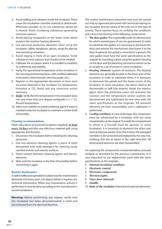
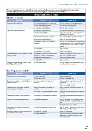
![CHAPTER 14 INCUBATOR
104
BASIC DEFINITIONS
Biochemical Oxygen Demand (BOD). Amount of oxygen required by aerobic microorganisms to decompose the organic matter in a sample. It is used as an indicator
of the degree of pollution of water. The (BOD) is measured as the mass in milligrams of oxygen used per litre of a sample when it is incubated at 20 °C over 6 days.
LED (Light-emitting diode). It is an electronic device which is widely used for displaying data on screens.
Resistance. Opposition that a material or electrical circuit imposes to the fl ow of electric current. It is the property of a circuit that transforms electrical energy into
heat as it opposes the fl ow of current. The resistance [R], of a body of uniform section such as a wire, is directly proportional to the length [l] and inversely proportional
to the sectional area [a]. The resistance is calculated by the following equation:
R = k × l
a
Where:
k = constant that depends on the units employed
l = Length of the conductor
a = sectional area of the conductor
The ohm (Ω) is the common unit of electrical resistance; one ohm is equal to one volt per ampere.
Thermal conduction. This is a form of heat transference within a substance when heat fl ows from the point of higher temperature to that of lower temperature.
Thermal convection. This is a form of heat transference through the movement of fl uid or air.
Thermistor. This is an electronic component, the resistance of which varies with temperature. They are low cost devices used in diverse applications; the most
common one is temperature control.
Thermocouple. A device for accurate measurement of temperature consisting of two dissimilar metals joined together at one end, producing a small voltage which
is proportional to the diff erence in temperature between the two when one of the connections has a higher temperature than the other. This phenomenon is known
as the “Seebeck eff ect” in honour of its discoverer, the German physician Thomas Seebeck.
Thermostat. This is a device which regulates the temperature of a system. In general, it operates by expanding one of its components which mechanically activates
another, for example a switch that controls a particular function.](https://image.slidesharecdn.com/b2df9d01-141207144322-conversion-gate01/85/B2-df9d01-117-320.jpg)
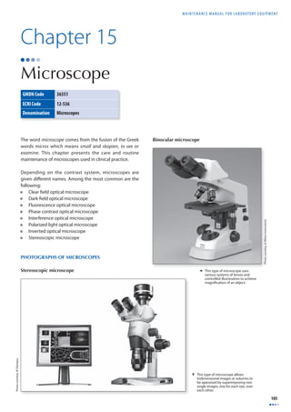
![CHAPTER 15 MICROSCOPE
106
PURPOSE OF THE EQUIPMENT
The microscope is a precision instrument with optical
subsystems (lenses, fi lters, prisms, condensers); mechanical
subsystems controlling the position of the sample in tri-dimensional
space X, Y, Z; electrical (transformers and light
source) and electronic subsystems (cameras, video, etc.)
interacting to amplify and control the image formation
of objects which are not detectable to the human eye. To
observe samples, it is essential to prepare these according
to techniques which emphasize details to be observed.
The microscope constitutes a diagnostic aid of fi rst order in
healthcare, in specialties such as haematology, bacteriology,
parasitology and in the training of human resources (there
are microscopes with specialized additions for students to
carry out observations directed by a professor). The technical
developments applied to microscopes have allowed the
design of numerous specialized models by the industry
and academia. These play a key role in developing human
knowledge and understanding the workings of nature.
OPERATION PRINCIPLES
The microscope is constructed using the physical properties
of lenses interacting with light. A lens is an optical element
usually made of glass which can refract light. It is of
calculated dimensions and in general has parabolic or
spherical surfaces. If light rays reaching one surface of the
lens converge in a common point F when exiting it, such
lens is known as positive or convergent. If it disperses the
light rays crossing it, it is divergent or negative. Positive
lenses (convergent) shown in Figure 41 constitute the
building blocks of microscopes.
In Figure 41, it is possible to identify the focus [F], (the point
where the light rays are concentrated) and how light is
refracted across the lens. The distance between the lens and
the focus is known universally as the focal distance [D].
Figure 42 summarizes concepts related to the functioning
of lenses applied to the design of microscopes.
Figure 41. Positive (convergent) lens
Figure 42. Optics of the convergent lens
Object [h’] located at a distance [a] from the
lens produces image [h] at a distance [b]
from the lens, where [h] = [h’]. The focus [F],
where the light waves are concentrated is at
the focal distance [f ] from the lens. See text
for additinal details and related equations.](https://image.slidesharecdn.com/b2df9d01-141207144322-conversion-gate01/85/B2-df9d01-119-320.jpg)
![Maintenance manual for laboratory equipment
107
When an illuminated object [h’] is placed at a distance [a]
in front of a convergent lens, light rays cross the lens and
are refracted. A ray crossing the upper part of the object
crosses the optical axis of the lens at the focal point [F’].
It is refracted by both surfaces of the lens and exits in one
direction, parallel to the optical axis. The ray crossing the
upper part of the object in parallel with the optical axis
passes through the lens and is refracted. It then travels
through the focal point [F] on the image’s side until it
crosses the first ray at a distance [b] from the lens where
the image is formed. In the case shown in Figure 42, the
distance [a] is greater than the focal distance [f’], where a
real image is formed inverted at a distance [b] behind the
lens. The focal distance [f ] is related to the distances [a] and
[b] in the equation:
The magnification [M] of a lens, defined by the relationship
between the size of the object and the size of the image
formed is represented by the equation:
b
h
M = =
Where:
[h] and [h’] correspond respectively to the dimensions
of the image and the object; [a] and [b] to the distances
between the lens and the point where the image is formed
and between the lens and the point where the object is
located.
€
1
f
= 1
a
+ 1
b
a
h
'
/
Figure 43. Diagram of a microscope](https://image.slidesharecdn.com/b2df9d01-141207144322-conversion-gate01/85/B2-df9d01-120-320.jpg)
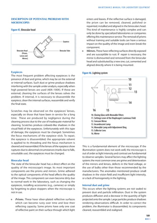
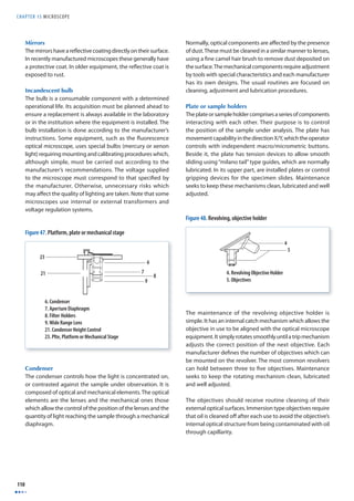
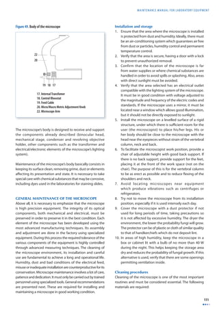
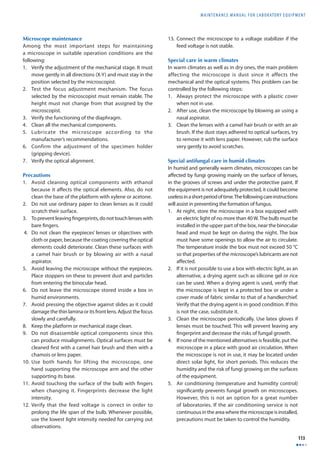
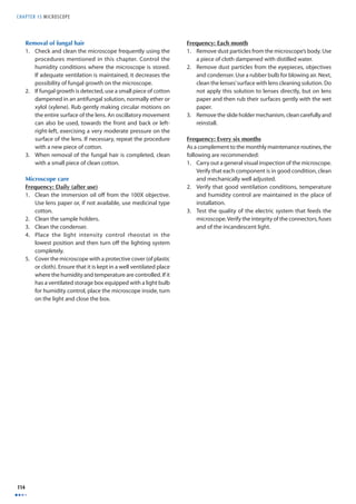
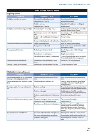
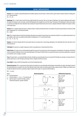
![MAINTENANCE MANUAL F O R LABORATORY EQUIPMENT
117
Propanol. Also known as isopropyl alcohol and prepared by the hydration of propylene. It is used as a solvent as well as in the preparation of acetone. Its boiling
point is 83 °C and chemical formula:
CH3 – CHOH – CH3
Range of useful magnifi cation. [RUM] of an objective/eyepiece combination is defi ned by the numerical aperture of the system. For perceiving the details of
an image, a minimum magnifi cation traditionally between 500 and 1000 times the numerical aperture [NA] of the objective is required. {Acceptable from RUM =
(500) x [NA] to (1 000) x [NA]}.
Refraction index. Value calculated by comparing the speed of light in space and in a second medium of greater density. It is normally represented by the letter [n]
or [n´] in technical literature or in mathematical equations.
Resolution. The ability to distinguish the fi nest details from a slide or particular sample. Among factors which most infl uence achieving a good resolution are the
numerical aperture, the type of sample, the lighting, the aberration correction and the type of contrast used. It is one of the most important characteristics of the
microscope.
Revolving objective holder. Mechanical device designed for mounting the objectives and allowing rapid interchange by means of a rotational movement. Its
capacity depends on the type of microscope. In general, it varies between three and fi ve objectives.
Xylene. Ethyl benzene isomer obtained from coal. It is used as a solvent and also in the preparation of dyes and lacquers. Its boiling point is 138 °C / 144 °C and
chemical formula:
CH3
C6H4
CH3](https://image.slidesharecdn.com/b2df9d01-141207144322-conversion-gate01/85/B2-df9d01-130-320.jpg)

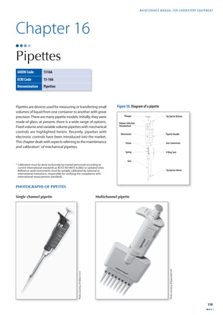
![CHAPTER 16 PIPETTES
120
PURPOSE OF THE PIPETTES
Pipettes are devices widely used in clinical and research
laboratories to supply very exact quantities of fl uids.
OPERATION PRINCIPLES OF THE PIPETTE
The mechanical or piston pipette generally functions by
manually transmitting force exercised on a plunger. The
plunger is an axis connected to a piston which moves along
a fi xed length cylinder, forcing a predetermined volume of
liquid outside or inside the pipette.
There are two types of piston pipettes: the fi xed volume
type with a predetermined liquid volume known as nominal
volume [Nv] and the variable volume type, which allows
adjusting of the volume dispensed within a determined
range depending on the pipette’s specifi cations. Volume
adjustment is achieved by modifying the range of the
piston’s movement inside the plunger. In variable volume
pipettes, the nominal volume is the maximum volume
the pipette can hold according to the manufacturer’s
specifi cations.
Fixed volume and variable volume pipettes can be
subdivided into two types: A and B. Pipettes of the type
A are named air displacement pipettes due to the fact that
there is a volume of air between the head of the piston and
the liquid in the cylinder (see pipette No. 1, Figure 51). Type
B pipettes are called positive displacement pipettes or direct
displacement pipettes as the piston is in direct contact with
the liquid (see pipette No. 2). Figure 44 shows diff erences
between these types of pipettes.
Air displacement pipettes have the advantage of presenting
less risks of contamination when heavily used. However,
they are not as precise as positive displacement pipettes
when working with very small volumes of liquid due to the
compressibility of air. All piston pipettes have disposable tips
for minimizing risks of contamination. It is recommended
to exclusively use tips provided by the manufacturer or
compatible with the specifi c pipette to guarantee their
correct adjustment to the pipette’s body as well as volumes
dispensed. In order to facilitate identifying these volumes,
some manufacturers have adopted a colour code which
simplifi es the identifi cation of the volumes to be dispensed.
The following table demonstrates this colour convention.
Table of pipette colour coding
Volume range in microlitres (μl) Colour
0.1–2.5 μl Black
0.5–10 μl Grey
2.0–20 μl Grey/Yellow
10–100 μl Yellow
50–200 μl Yellow
100–1000 μl Blue
500–2500 μl Red
REQUIREMENTS FOR USE
To use a pipette, the laboratory must be suitably clean and
well lit. The general conditions are the following:
1. Verify that room temperature is stable with an optimum
temperature of 20 °C with a variation range of ± 5 °C
(between 15 °C and 30 °C).
2. Confi rm that the relative humidity is higher than 50 %.
The pipettes and samples or liquid materials must be
stabilized to the conditions of the laboratory. Typically
it is recommended to equilibrate these in the laboratory
two to three hours before the work is performed.
3. Avoid working with pipettes under direct sunlight.
4. Use the appropriate protective elements if working with
toxic materials or those carrying a biological risk.
0
Figure 51. Types of pipettes](https://image.slidesharecdn.com/b2df9d01-141207144322-conversion-gate01/85/B2-df9d01-133-320.jpg)
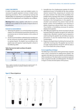
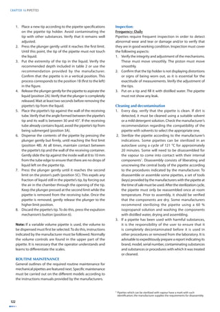
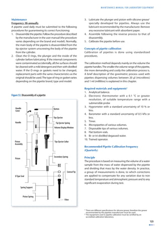
![CHAPTER 16 PIPETTES
124
This type of test allows the following:
1. To compare diff erent types of pipettes to each other to
detect if there are diff erences among them.
2. To check the precision and exactitude of a pipette.
3. To check the exactitude and precision of a batch of
pipettes.
4. To check factors attributable to the use of one pipette
by several users.
Procedure1
The procedure explained next is valid for air displacement
pipettes. It includes the following steps:
1. Install a new tip on the pipette.
2. Pipet distilled water and empty into the waste container.
Repeat at least 5 times in order to stabilize the humidity
of the air inside the pipette.
3. Add water to the weighing receptacle until the level of
liquid reaches at least 3 mm.
4. Register the temperature of the water, environmental
pressure and relative humidity.
5. Cover the weighing receptacle, if this applies.
6. Register the weight shown on the balance or press tab
so that the reading is zero (0).
7. Fill the pipette with water from the storage container
and dispense it into the weighing receptacle expelling
all the water. This is done in the same way pipettes are
used on a daily basis (see step 7 of the Correct pipetting
technique).
8. Register the new weight detected by the balance.
9. Repeat steps 7 and 8 nine (9) additional times, recording
the weight registered by the balance at the end of each
cycle.
10. Register the temperature of the liquid inside the weighing
receptacle at the end of the tenth cycle and measure the
time elapsed since the measurements started.
11. Evaluate if evaporation has been signifi cant (this is critical
when working with pipettes of very small volumes). If
this is the case, an additional period of time [Ta] equal
to the time used during the ten measurements must be
allowed to elapse, and when completed, a new reading
has to be carried out.
12. The mass of water lost by evaporation in the additional
time [Ta] is divided by the total number of samples
analyzed (ten). This will give an indication of the average
mass of liquid lost due to evaporation per cycle. This
fi gure must be added to each of the mass readings.
Calculations
Proceed as follows:
1. Calculate the mass of water dispensed by the pipette
in each cycle. Subtract the reading registered at the
end of the previous cycle to the reading registered
in the current cycle. Repeat for all measurements. If
appropriate, add the average mass corresponding to
the calculated evaporation per cycle.
2. Convert each mass value to a volume at 20 °C, dividing
the mass by the density of water adjusted to the
mentioned temperature.
Vi = Mi
D
3. Calculate the average of the volumes calculated in
step 2. (The sum of volumes, divided by the number
of samples). Apply the adjustments per phenomenon
such as the air pressure onto the mass (fl otation). To
accomplish this, multiply each mass by a correction
factor [Z].
X =ΣVi n × Z
4. Calculate the standard deviation of the sample.
SD = 1
n −1
nΣ
× Xi − XAV ( )2
i=1
5. Calculate the coeffi cient of variation.
[Cv]CV (%) = S
XAV
×100
A table containing a summary of the mathematical formulae
mentioned is shown next.
Table of mathematical formulae
X = Vi Σ n × Z
SD = 1
n −1
nΣ
× Xi − XAV ( )2
i=1
E s = X −Vn
[Cv]CV (%) = S
XAV
−
X X
AV Nom
X
Nom
Vi = Mi
D
D
% =
Conventions: Conventions:
X =average volume
SD = standard deviation
Z = adjustment factor in
(μl / mg)2
×100
CV(%) = variation coeffi cient
D(%) = error
1 The procedure presented is a general guide. For complete details, consult
the standards BS ES ISO 8655-6:2002 or current updates.
2 The values Z depend on the temperature and pressure of distilled
water. Refer to specialized publications such as the Standard BS EN ISO
8655-6:2002, Attachment A.](https://image.slidesharecdn.com/b2df9d01-141207144322-conversion-gate01/85/B2-df9d01-137-320.jpg)
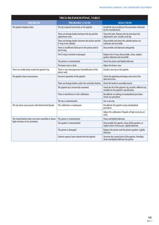
![CHAPTER 16 PIPETTES
126
BASIC DEFINITIONS
Coeffi cient of variation [%CV]. A statistical parameter representing the ratio of the standard deviation of a distribution to its mean.
Density. Relationship between a body’s mass and the volume which it occupies. The average density of an object is equal to its total mass divided by its total volume.
It is identifi ed by the Greek letter Ro [ρ]. In the International System of Units, density is measured in kilograms by cubic metres [kg/m3].
Error (of a measurement). A diff erence shown between the value measured and the correct value.
Exactitude. A concept related to errors shown in measurements. It is said that an instrument is exact when the value of a group of measurements are suffi ciently
close to the real value.
Mass. A physical property of the bodies related to the quantity of matter these contain, expressed in kilograms (kg). In physics, there are two quantities to which the
name mass is given: gravitational mass which is a measure of the way a body interacts with the gravitational fi eld (if the body’s mass is small, the body experiences
a weaker force than if its mass were greater) and the inertial mass, which is quantitative or numerical measure of a body’s inertia, that is, of its resistance to being
accelerated.
Microgram [μg]. A unit of weight equivalent to 1 x 10⁻⁶ grams (g).
Microlitre [μl]. A unit of capacity equivalent to 1 x 10⁻⁶ litres (l). One (1) μl of water weighing exactly one (1) mg and has a volume of 1 mm3.
Milligram [mg]. A unit of weight equivalent to 1 x 10⁻³ grams (g).
Millilitre [ml]. A unit of capacity equivalent to 1 x 10⁻³ litres (l). One (1) ml of water weighing exactly (1) g and has a volume of 1 cm3.
Precision. A concept related to errors shown in measurements. An instrument or method is precise when upon repeating a measurement in independent tests,
the results obtained are similar.
Range. A diff erence between the maximum and minimum value which an instrument reads or measures.
Standard deviation [SD]. Measure of the dispersion of a set of data from its mean. The more spread apart the data is, the higher the deviation. It is used as a
statistical parameter for determining the global error of a sample set.
Volume. A quantity of physical space that a mass occupies. It is calculated by dividing the mass by its average density.](https://image.slidesharecdn.com/b2df9d01-141207144322-conversion-gate01/85/B2-df9d01-139-320.jpg)
![MAINTENANCE MANUAL F O R LABORATORY EQUIPMENT
127
Chapter 17
Stirring Heating Plate
GMDN Code 36815
ECRI Code 16-287
Denomination Heating Plates
The stirring heating plate or heated stirring heating plate
has been developed to heat and mix fluids contained
in laboratory receptacles such as fl asks, test tubes and
beakers.
PHOTOGRAPH OF THE STIRRING HEATING PLATE
Selected / Actual Temperature
Display Screen
Temperature Mode
On/Off Button
Temperature
Selection Button
HEAT AGIT
RESET
Temperature
Scale Button
Selected / Actual Speed
Display Screen
Agitation Mode On/Off Button
Reset Button
Agitation Speed Button
Figure 54. Stirring heating plate controls
OPERATION PRINCIPLES
Generally, the stirring heating plate has a fl at surface on
which are placed receptacles containing fl uids to be heated
and agitated. Its surface is made of good thermal conductors
such as aluminium [Al] or ceramic materials. Some heating
plates exclusively use radiation sources such as infrared
(infrared light) for heating. Stirring hot plates have a heating
element (an electrical resistor), a control system (on and off ,
temperature control, agitation control and its respective
motor). The motors used in these types of instruments are
generally of single phase induction named shaded pole1.
The speed range depends on the number of poles and the
frequency of the feed voltage.
Temperature:
Room Temperature up to approximately 500 °C.
Rotation speed:
From 60 RPM up to approximately 1200 RPM.
CONTROLS OF THE STIRRING HEATING PLATE
The diagram in Figure 54 includes a typical control found on
a stirring heating plate. The diagram shown corresponds to
a microprocessor-regulated heating plate which is found in
most modern equipment.
1 The power of these motors is
approximately 1/20 hp; these
are characterized by having a
low torque and being low in
price. They are called shaded pole
induction motors.
Photo courtesy of Cole-Parmer Instrument Co.](https://image.slidesharecdn.com/b2df9d01-141207144322-conversion-gate01/85/B2-df9d01-140-320.jpg)
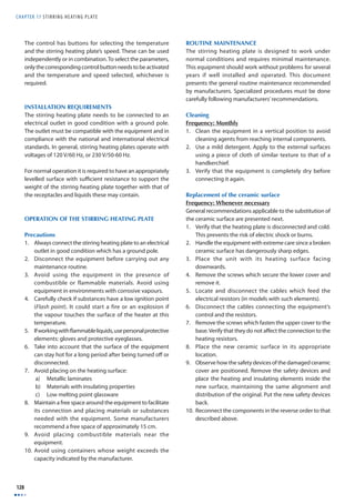
![MAINTENANCE MANUAL F O R LABORATORY EQUIPMENT
129
Main Bobbin
Secondary Bobbin
Stator
Rotor
Poles
Figure 55. Induction motor
Replacement of fuses
Frequency: Whenever necessary
If the stirring heating plate is connected and the main
switch is in the on position but it is not warming up, it is
possible that a fuse needs to be changed. The following is
the process for changing the fuse:
1. Place the main switch in the off position and disconnect
the electrical feed cable.
2. Remove the top of the fuse compartment with a fl at
screwdriver.
3. Replace the fuse by a new one with the same
specifi cations as the original.
4. Replace the fuse’s compartment cover.
TROUBLESHOOTING TABLE
PROBLEM PROBABLE CAUSE SOLUTION
There is no electrical power. There is a failure in the protection fuse. Substitute the protection fuse.
There is a failure in the electrical connection feeding
the equipment.
Check the state of the electrical connection.
The equipment is disconnected from the electrical
feed outlet.
Connect the equipment to the electrical outlet.
The electrical feed cable is defective. Substitute the electrical feed cable.
The plate shows no sign of warming up. The heating function has not been selected. Activate the heating function on the control panel.
The heating resistor is out of service. Substitute the heating resistor. Install replacement
parts with the same characteristics as the original.
There is no rotation. The rotation function has not been selected. Activate the rotation control on the control panel.
BASIC DEFINITIONS
Erlenmeyer. A glass container used in laboratories to put or measure substances.
Shaded pole motor. An induction motor used in small machines. It is characterized by having a bobbin (squirrel cage rotor) requiring a rotating magnetic fi eld for
starting. Each fi eld pole has a shading coil (copper ring) which induces currents causing the magnetic fl ow to become imbalanced in relation to the fl ow in the other
portion, producing a torque in the rotor. These motors are low cost and low effi ciency. Their speed can be calculated by means of the equation:
n(rpm) = 120 f
p
Where:
[n] = synchronous speed in revolutions per minute
[f] = frequency of voltage applied
[p] = number of poles in the stator
A diagram is included showing the inner part of the electrical circuits.
Ignition point. The temperature at which molecules of a substance react with oxygen in the air, initiating combustion. This temperature is called Flash Point.](https://image.slidesharecdn.com/b2df9d01-141207144322-conversion-gate01/85/B2-df9d01-142-320.jpg)

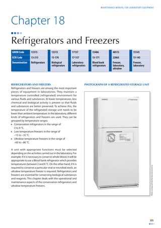
![CHAPTER 18 R E F R I G E RATORS AND F R E E Z E R S
132
PURPOSE OF REFRIGERATED STORAGE UNITS
Refrigerators and freezers are used for the conservation
of blood and its derivatives, biological liquids and tissues,
reagents, chemicals, and stocks. In general, the higher the
temperature the more chemical and biological activity
is present. By reducing temperature, one can control the
eff ects on the composition and structure of substances to be
preserved. In the laboratory, systems of refrigeration are used
for conserving substances such as reagents and biological
elements which would otherwise decompose or lose their
properties. Refrigeration, as a technique off ers conditions
which renders possible the conservation of elements such as
blood and its derivatives needed for diagnosis, surveillance
and for providing health services. It is possible to achieve
extremely low temperature ranges, such as those used for
master stocks conservation (–86 °C) or temperatures within
the range of 2 and 8 °C, which is suffi cient for conserving
reagents and diverse biological products.
OPERATION PRINCIPLES
Refrigerators and freezers function according to laws of
physics regulating the energy transfer where temperature
diff erences exist. From the second law of thermodynamics
it is known that, if thermal energy needs to be transferred
from a point with low temperature to another with high
temperature, a mechanical task needs to be carried out.
Modern refrigerators and freezers are thermal systems
which function mainly using a cycle called compression,
where refrigerant gas with special properties achieving heat
transference is used. This chapter focuses on explaining how
refrigerators and freezers using compression operate.
High Pressure
Zone
Exterior Ta
Qh Qh Qh Qh Qh Qh Qh 2
3 Condenser
Expansion
Valve
Filter
4
Low Pressure Zone
[4-1]
QI QI QI QI QI QI QI
Evaporator
Refrigerator Environment Ta
[2-3]
Refrigerant Fluid: Ideal Compression Cycle
2
3 2’
4’ 4
S
T
Compressor
Thermal
Isolation
1
Figure 56. Refrigeration circuit
Refrigeration circuit
The basic circuit shown in Figure 56 demonstrates how
a refrigerator functions. On the left side it is possible
to distinguish the following components: evaporator,
condenser, compressor, expansion valve, filter and
interconnection tubing. Within each one of these
components, refrigerant gas circulates.
On the right side of the figure is shown a graph of
temperature [T] versus entropy [S], which demonstrates the
functioning of an ideal1 refrigeration cycle. The numbers on
the basic diagram on the left show points of the adiabatic
processes (compression [1-2] and choking [3-4]) and the
processes involved in heat transference (in the evaporator –
refrigerated environment [4-1], in the condenser [2-3] on the
exterior). The complete cycle is described as the sequence
of processes [1-2-3-4-1].
Evaporator. Contains a network of channels through which
the refrigerant gas circulates. In the evaporator, a process of
heat transference [Ql] occurs at a constant pressure. In order
for the refrigeration process to occur, the environment to
be refrigerated must be surrounded by a system of thermal
isolation. This is to prevent thermal energy from entering
the evaporator’s zone of infl uence at the same rate as the
refrigerant gas absorbs it. The refrigerant gas enters into
a liquid phase in the evaporator by point [4] (ideal) or [4’]
(real) and while it passes through the network of evaporator
channels, it absorbs heat [Ql] and progressively transforms
into vapour. When the refrigerant gas reaches point [1],
it is under the form of vapour. It is then suctioned by the
compressor through a tube or line.
1 The real cycle diff ers from the ideal cycle by some irreversible processes not
indicated in the graph for the sake of clarity and simplicity.](https://image.slidesharecdn.com/b2df9d01-141207144322-conversion-gate01/85/B2-df9d01-145-320.jpg)
![MAINTENANCE MANUAL F O R LABORATORY EQUIPMENT
133
Compressor. Usually propelled by an electric motor, the
compressor suctions the vaporized refrigerant from the
evaporator (saturated) at low pressure and by means of
a piston or set of pistons, exercises a process of reversible
adiabatic compression on it (without heat transfer) between
points [1-2]. Upon being discharged from the compressor,
the vapour is hot as a result of the compression process and
is delivered to the condenser in point [2].
Condenser. Similar device to the evaporator, which has
a network of channels through which the refrigerant gas
circulates. As the temperature of the refrigerant is higher
than ambient temperature [Ta], a heat transference process
[Qh] is produced from the refrigerant to the environment
at constant pressure. To facilitate heat transference, the
condenser tubes have thin fi ns which increase the transfer
surface. As heat continues to be lost [Qh] as a result of the
process of transference, the refrigerant returns to its liquid
phase until it reaches point [3] as saturated liquid where it
enters the expansion valve.
Expansion valve. Allowing the refrigerant to flow in a
controlled manner, the valve exercises a resistance on the
passage of the refrigerant to avoid any heat transference
by an adiabatic process. As a result, the pressure in the
valve is reduced in a drastic way in point [4]. A fi lter is
generally installed at the exit of the expansion valve. Some
manufacturers replace the expansion valve by a capillary
tube which has an equivalent restrictive effect on the
passage of the cooling fl uid.
Filter. Retains humidity and impurities which may be
present in the refrigerant. At the back of the fi lter, the system
is connected again to the evaporator at point [4] and the
cycle described is repeated.
Liquid collector. Sometimes placed by manufacturers
before the refrigerant enters the compressor. Its purpose
is to retain any portion of that fluid in liquid phase to
guarantee that only vaporized refrigerant gas enters the
compressor (not shown in the refrigeration diagram).
Thermal insulation. Set of materials with the property
of slowing heat transference. Its function consists of
preventing thermal energy from the environment to reach
the refrigeration area at the same rate as the system extracts
the internal thermal energy. All refrigeration equipment has
adequate thermal isolation for this purpose. Among the most
commonly used insulation materials are polyurethane foam
and glass wool. Similarly, it is customary to manufacture
interior surfaces in materials such as ABS plastic.
Service valves. Valves used for loading the refrigeration
circuit with refrigerant gas. By means of these valves, the
draining and filling systems are connected so that the
refrigerated storage unit operates according to specifi cations
established by the manufacturer. Only the manufacturer
and specialized technical personnel have access to these
valves (not indicated in the refrigeration diagram).
Thermal protector. This is a protective device which is
activated and disconnects the compressor in case overloads
aff ecting the bobbins in the compressor’s fi eld occur (It
pertains to the electrical system and is not indicated in the
refrigeration system’s diagram).
Note: The evaporator, as well as the condenser are made
of materials with good thermal conduction properties
such as aluminium [Al] and copper [Cu]. To improve heat
transference, ventilation systems which induce forced
convection processes have been incorporated. To attain the
diff erent temperatures (refrigeration) required in laboratories
or in the industry, manufacturers have developed diverse
designs and refrigerants for the targeted results.
INSTALLATION REQUIREMENTS
For their functioning refrigerators and freezers require the
following precautions:
1. An electrical connection with a ground pole appropriate
to the voltage and frequency of the equipment. In
general depending on their capacity, refrigerators and
freezers can be obtained in versions with 115 V, 60 Hz
and 220-240 V, 50 Hz. Electrical connections complying
with international and national electric standards used
in the laboratory must be anticipated.
2. If more than one unit installed depend on the same
electrical circuit, it must be verifi ed that the capacity
(electrical power) and safety devices are adequate
for supplying the amount of power required by these
units.
3. Directly connect the unit to the electrical outlet. Never
connect a unit to an overloaded electrical outlet or one
with voltage defi ciencies. Avoid the use of electrical
extensions. The electrical outlet must not be more than
2 m from the unit.
4. Install the unit on a levelled surface, leaving free space
around the equipment. Refrigerators and freezers have
a levelling system at their base which allows them
to adjust to small diff erences in level of the fl oor. It is
customary to leave a free space of 15 cm at the sides
and at the back of the unit to facilitate ventilation of
the condenser.
5. Avoid installing the unit under direct sunlight or near a
heat source such as radiators or heaters. Remember that
the greater the diff erence in temperature is between the
environment and the condenser, the more effi cient will
the heat transference be.](https://image.slidesharecdn.com/b2df9d01-141207144322-conversion-gate01/85/B2-df9d01-146-320.jpg)
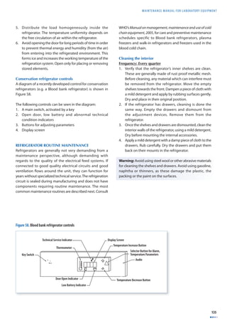
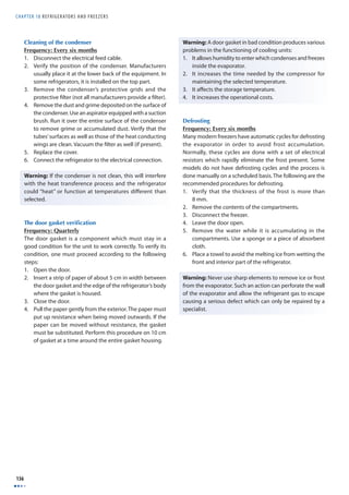
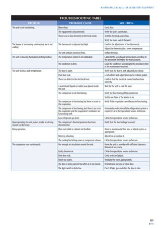
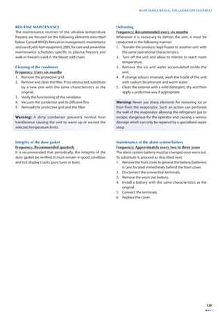
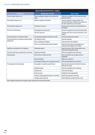
![MAINTENANCE MANUAL F O R LABORATORY EQUIPMENT
141
BASIC DEFINITIONS
Adiabatic process. A process in which there is no transference of heat. This implies ΔQ= 0.
BTU. This is a unit for determining the heat transference in the English System. BTU is the acronym for the British Thermal Unit. One BTU is the quantity of heat that
must be transferred for increasing the temperature of one pound of water from 63 °F to 64 °F.
Calorie. This is a quantity of heat which must be transferred to a gram of water to raise the temperature by 1 °C. This defi nition applies when under normal conditions
(atmospheric pressure equal to 760 mm Hg, gravity acceleration equal to 9.81 m/s2); the temperature of a gram of water is increased from 14.5 to 15.5 °C.
Entropy. Measure of a system’s energy that is unavailable for work, or of the degree of a system’s disorder. The reversible diff erential changes of entropy are expressed
by means of the following equation:
dS = dQ
T
Where:
dQ: heat absorbed from a reserve at temperature T during an infi nitesimal reversible change of the state.
T: temperature of the reserve.
The following equation must be carried out for any reversible cycle change.
ΔS = dS = dQ
∫ = 0
T
If the cycle is irreversible, it must be:
ΔS = dQ
T ∫ 0
Heat. This is a form of transferred energy over the limit of a system at a given temperature, to another one at a lower temperature by virtue of the temperature
diff erence between the two systems. When a system of great mass [M] is placed in contact with another of small mass [m’] at a diff erent temperature, the resulting
fi nal temperature is close to the initial temperature of the greater mass system. It is therefore said that a quantity of heat ΔQ has been transferred from the system
of higher temperature to the system of lower temperature. The heat quantity ΔQ is proportional to the change in temperature ΔT. The proportion constant [C], called
the system’s caloric capacity, allows the following relationship ΔQ=CΔT to be established, from which it is inferred that one of the consequences of the change in
temperature in a system is the transference of heat.
Latent heat. The quantity of thermal energy required for a change in phase to occur in a substance, for example: from liquid phase to vapour phase.
Refrigerant gas. A substance (i.e. coolant) used as a medium in the processes of heat absorption.
Specifi c heat. The quantity of heat required to increase the unit of mass by one degree.
Sensitive heat. The quantity of energy required for increasing the temperature of the refrigerant gas upon absorbing heat. For example: the quantity of heat
required for raising the temperature from 15 to 20 °C or from 30 to 40 °C.
Thermal system. A device which operates in a thermodynamic cycle and carries out a certain positive quantity of work as a result of the transference of heat
between a body at high temperature to a body at low temperature.](https://image.slidesharecdn.com/b2df9d01-141207144322-conversion-gate01/85/B2-df9d01-154-320.jpg)

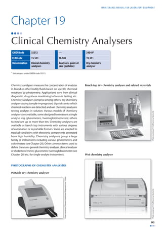
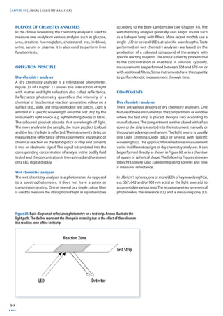
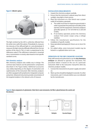
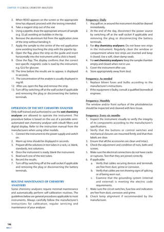
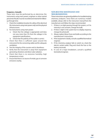
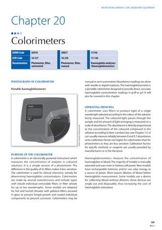
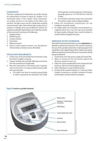
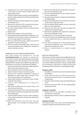
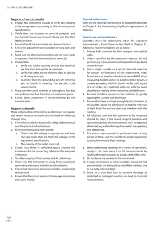


This document is the second edition of a maintenance manual for laboratory equipment published by the World Health Organization (WHO) in 2008. It contains 19 chapters that provide information on the purpose, operation principles, installation requirements, routine maintenance, and troubleshooting for common pieces of laboratory equipment such as microplate readers, pH meters, balances, incubators, centrifuges, and refrigerators. The manual is intended to help users properly operate and maintain this equipment.


![PERI-PROSTHETIC FRACTURE NAIL-PLATE CONSTRUCT [NPC].pptx](https://cdn.slidesharecdn.com/ss_thumbnails/drarunkumardrmohamedashrafperiprostheticfrasturenail-plateconstructnpc-260209164459-7e9d15a1-thumbnail.jpg?width=640&height=640&fit=bounds)


