Download to read offline

![2
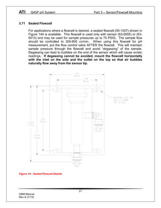
O&M Manual
Rev-X (7/15)
Table of Contents
PART 1 - INTRODUCTION..................................4
1.1 General (Q45P, pH Monitor) ............4
1.2 Features ..........................................5
1.3 Q45P System Specifications............5
1.4 Q45P Performance Specifications ...6
1.5 General – Q25P pH Sensor .............7
1.6 Sensor Features ..............................7
1.7 Q25P Sensor Specifications ............7
PART 2 – ANALYZER MOUNTING.....................9
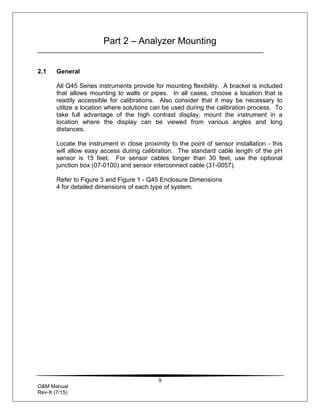
2.1 General............................................9
2.2 Wall or Pipe Mount.........................11
PART 3 – SENSOR/FLOWCELL MOUNTING ..13
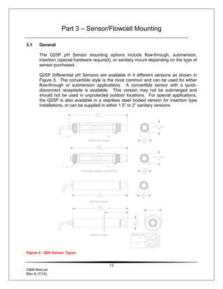
3.1 General..........................................13
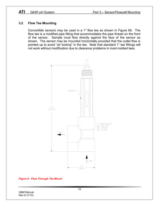
3.2 Flow Tee Mounting ........................14
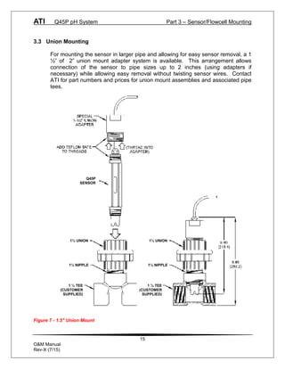
3.3 Union Mounting..............................15
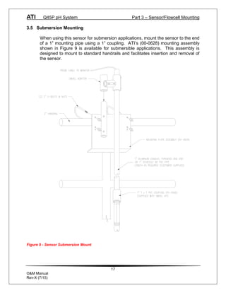
3.5 Submersion Mounting ....................17
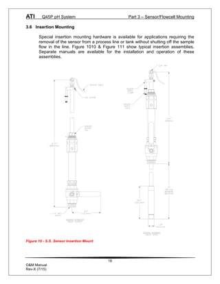
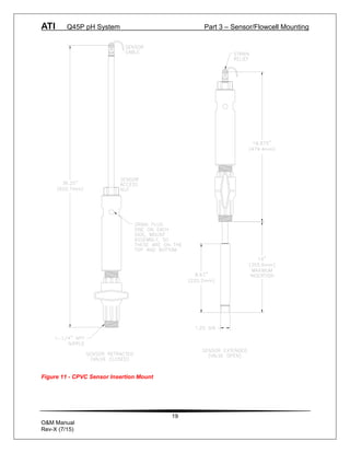
3.6 Insertion Mounting .........................18
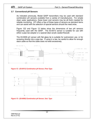
3.7 Conventional pH Sensors ..............20
3.71 Sealed Flowcell..............................21
3.72 Flow Tee Adapter...........................22
3.8 Lock-n-Load System......................23
PART 4 – ELECTRICAL INSTALLATION.........24
4.1 General..........................................24
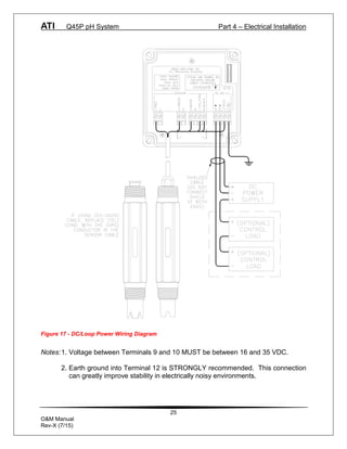
4.2 Two-Wire .......................................24
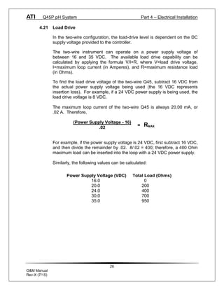
4.21 Load Drive .....................................26
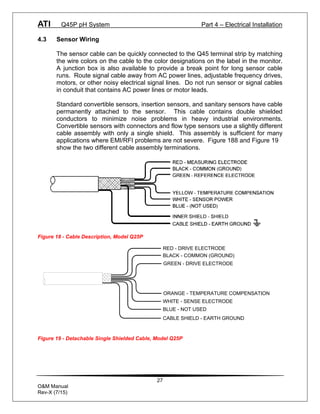
4.3 Sensor Wiring ................................27
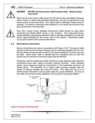
4.4 Direct Sensor Connection ..............28
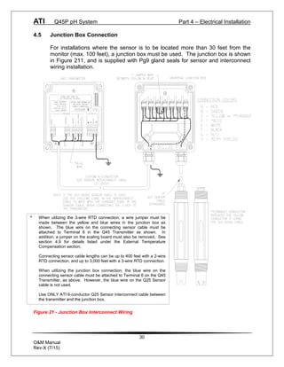
4.5 Junction Box Connection ...............30
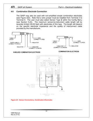
4.6 Combination Electrode
Connection.............................................31
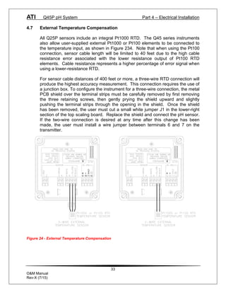
4.7 External Temperature
Compensation ........................................33
4.8 External Preamplifier......................34
PART 5 – CONFIGURATION.............................35
5.1 User Interface.................................35
5.11 Keys...............................................36
5.12 Display ...........................................36
5.2 Software.........................................38
5.21 Software Navigation ......................38
5.22 Measure Menu [MEASURE]...........41
5.23 Calibration Menu [CAL]..................42
5.24 Configuration Menu [CONFIG] .......43
5.25 Control Menu [CONTROL] .............46
PART 6 – CALIBRATION..................................51
6.1 Overview and Methods...................51
6.11 Sensor Slope..................................51
6.12 Sensor Offset .................................52
6.13 2-Point Calibration Explained .........52
6.14 1-Point Calibration Explained .........52
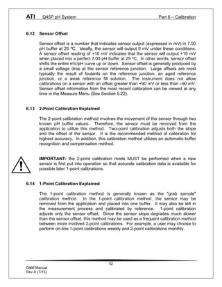
6.2 Performing a 2-Point Calibration.....53
6.3 Performing a 1-Point Calibration.....54
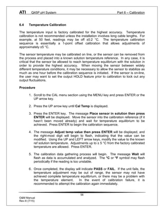
6.4 Temperature Calibration.................56
PART 7 – PID CONTROLLER DETAILS...........57
7.1 PID Description ..............................57
7.2 PID Algorithm.................................57
7.3 Classical PID Tuning......................59
7.4 Manual PID Override Control .........60
7.5 Common PID Pitfalls ......................60
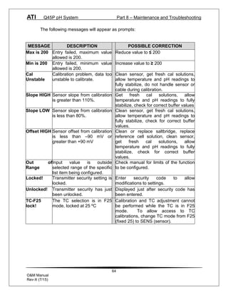
PART 8 – MAINTENANCE AND
TROUBLESHOOTING.......................................62
8.1 System Checks ..............................62
8.2 Instrument Checks .........................62
8.4 Cleaning the Sensor.......................67
8.5 Replacing the Saltbridge and
Reference Buffer Solution.......................68
8.6 Troubleshooting .............................69
SPARE PARTS..................................................71](https://image.slidesharecdn.com/q45p-2-wire-ph-transmitter-230608141209-3d24cdc6/85/Q45P-2-Wire-pH-Transmitter-pdf-3-320.jpg)

![ATI Q45P pH System Part 5 – Configuration
38
O&M Manual
Rev-X (7/15)
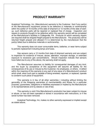
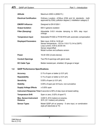
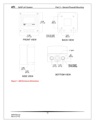
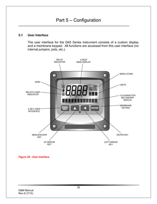
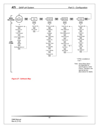
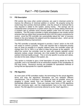
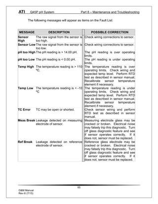
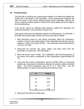
5.2 Software
The software of the Q45P is organized in an easy to follow menu-based system.
All user settings are organized under five menu sections: Measure, Calibration
[CAL], Configuration [CONFIG], Control [CONTROL] and Diagnostics [DIAG].
Note: The default Measure Menu is display-only and has no menu icon.
5.21 Software Navigation
Within the CAL, CONFIG, CONTROL, and DIAG menu sections is a list of
selectable items. Once a menu section (such as CONFIG) has been selected
with the MENU key, the user can access the item list in this section by pressing
either the ENTER key or the UP arrow key. The list items can then be scrolled
through using the UP arrow key. Once the last item is reached, the list wraps
around and the first list item is shown again. The items in the menu sections are
organized such that more frequently used functions are first, while more
permanent function settings are later in the list. See Figure 277 for a visual
description of the software.
Each list item allows a change to a stored system variable. List items are
designed in one of two forms: simple single variable, or multiple variable
sequence. In the single variable format, the user can quickly modify one
parameter - for example, changing temperature display units from °F to °C. In
the multiple variable sequence, variables are changed as the result of some
process. For example, the calibration of pH generally requires more than one
piece of information to be entered. The majority of the menu items in the
software consist of the single variable format type.
Any data that may be changed will be flashing. This flashing indicates user entry
mode and is initiated by pressing the ENTER key. The UP arrow key will
increase a flashing digit from 0 to 9. The LEFT arrow key moves the flashing
digit from right to left. Once the change has been completed, pressing ENTER
again stores the variable and stops the flashing. Pressing ESC aborts the
change and also exits user entry mode.
The starting (default) screen is always the Measure Menu. The UP arrow key is
used to select the desired display. From anywhere in this section the user can
press the MENU key to select one of the four Menu Sections.
The UP arrow icon next to all list items on the display is a reminder to scroll
through the list using the UP arrow key.](https://image.slidesharecdn.com/q45p-2-wire-ph-transmitter-230608141209-3d24cdc6/85/Q45P-2-Wire-pH-Transmitter-pdf-39-320.jpg)
![ATI Q45P pH System Part 5 – Configuration
41
O&M Manual
Rev-X (7/15)
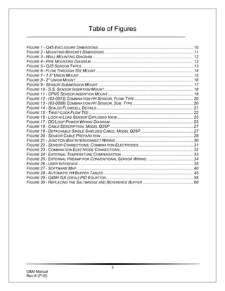
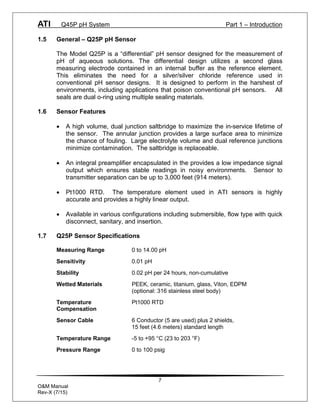
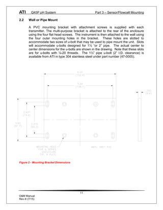
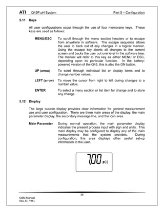
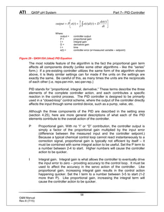
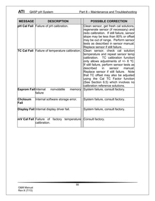
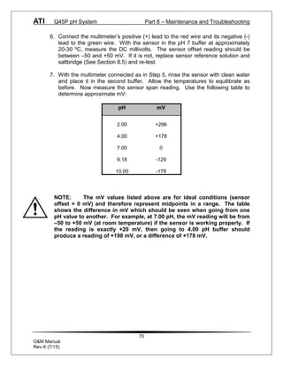
5.22 Measure Menu [MEASURE]
The default menu for the system is the display-only menu MEASURE. This menu
is a display-only measurement menu, and has no changeable list items. When
left alone, the instrument will automatically return to this menu after
approximately 30 minutes. While in the default menu, the UP arrow allows the
user to scroll through the secondary variables on the lower line of the display. A
brief description of the fields in the basic transmitter version is as follows:
TRANSMITTER MEAS SCREENS:
25.7° Temperature display. Can be displayed in °C or °F,
depending on user selection. A small “m” on the left side of
the screen indicates the transmitter has automatically
jumped to a manual 25°C setting due to a failure with the
temperature signal input.
+132 mV Raw sensor voltage. Useful for diagnosing problems.
100% 20.00 mA Shows the present controller output level on left, and actual
[Iout1=PID] transmitter current on the right. The controller can be placed
in manual while viewing this screen by pressing and holding
the ENTER key for 5 seconds until a small flashing “m”
appears on the screen. At that point the controller output
can be adjusted up or down using the UP and LEFT arrow
keys. To return to automatic operation, press and hold the
ENTER key for 5 seconds and the “M” will disappear.
20.00 mA Transmitter output current.
Slope = 100% Sensor output response vs. ideal calibration. This value
updates after each calibration. As the sensor ages, the slope
reading will decay indicating sensor aging. Useful for
resolving sensor problems.
Offset = 0.0 mV Sensor output current at a zero ppm input. This value
updates after a zero-calibration has been performed. Useful
for resolving sensor problems.
Q45P v4.01 Transmitter software version number.
Note: A display test (all segments ON) can be actuated by pressing and
holding the ENTER key while viewing the model/version number on
the lower line of the display.](https://image.slidesharecdn.com/q45p-2-wire-ph-transmitter-230608141209-3d24cdc6/85/Q45P-2-Wire-pH-Transmitter-pdf-42-320.jpg)
![ATI Q45P pH System Part 5 – Configuration
42
O&M Manual
Rev-X (7/15)
The MEASURE screens are intended to be used as a very quick means of
looking up critical values during operation or troubleshooting.
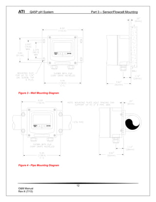
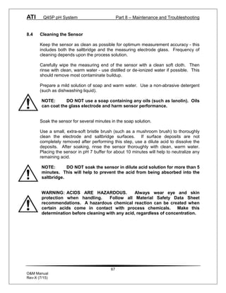
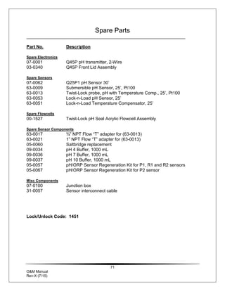
5.23 Calibration Menu [CAL]
The calibration menu contains items for frequent calibration of user parameters.
There are two items in this list: Cal pH, Cal Temp.
Cal pH The pH calibration function allows the user to adjust the
transmitter offset and span reading to match reference
buffers, or to adjust the sensor offset to match the sample
reading. See Part 6 - Calibration for more details.
Cal Temp The temperature calibration function allows the user to
adjust the offset of the temperature response by a small
factor of ±5 °C. The temperature input is factory calibrated
to very high accuracy. However, long cable lengths and
junction boxes may degrade the accuracy of the temperature
measurement in some extreme situations. Therefore, this
feature is provided as an adjustment. See Part 6 -
Calibration for more details.](https://image.slidesharecdn.com/q45p-2-wire-ph-transmitter-230608141209-3d24cdc6/85/Q45P-2-Wire-pH-Transmitter-pdf-43-320.jpg)
![ATI Q45P pH System Part 5 – Configuration
43
O&M Manual
Rev-X (7/15)
5.24 Configuration Menu [CONFIG]
The Configuration Menu contains all of the general user settings:
Entry Lock This function allows the user to lock out unauthorized
tampering with instrument settings. All settings may be
viewed while the instrument is locked, but they cannot be
modified. The Entry Lock feature is a toggle-type setting;
that is, entering the correct code will lock the transmitter and
entering the correct code again will unlock it. The code is
preset at a fixed value. Press ENTER to initiate user entry
mode and the first digit will flash. Use arrow keys to modify
value. See the last page of this manual for the Q45P
lock/unlock code. Press ENTER to toggle lock setting
once code is correct. Incorrect codes do not change state of
lock condition.
Set Delay The delay function sets the amount of damping on the
instrument. This function allows the user to apply a first
order time delay function to the pH measurements being
made. Both the display and the output value are affected by
the degree of damping. Functions such as calibration are
not affected by this parameter. The calibration routines
contain their own filtering and stability monitoring functions to
minimize the calibration timing. Press ENTER to initiate user
entry mode, and the value will flash. Use the arrow keys to
modify value; range is 0.1 to 9.9 minutes. Press ENTER to
store the new value.
Contrast This function sets the contrast level for the display. The
custom display is designed with a wide temperature range,
Super-Twist Nematic (STN) fluid.
The STN display provides the highest possible contrast and
widest viewing angle under all conditions. Contrast control
of this type of display is generally not necessary, so contrast
control is provided as a means for possible adjustment due
to aging at extreme ranges. In addition, the display has an
automatic temperature compensation network. Press
ENTER to initiate user entry mode, and the value will flash.
Use arrow keys to modify the value; range is 0 to 8 (0 being
lightest). Press ENTER to update and store the new value.](https://image.slidesharecdn.com/q45p-2-wire-ph-transmitter-230608141209-3d24cdc6/85/Q45P-2-Wire-pH-Transmitter-pdf-44-320.jpg)
![ATI Q45P pH System Part 5 – Configuration
44
O&M Manual
Rev-X (7/15)
Main This function allows the user to change the measurement in
Display the primary display area. The user may select between pH, sensor
temperature, or output current. Using this function, the user may
choose to put temperature in the main display area and pH on the
secondary, lower line of the display. Press ENTER to initiate user
entry mode, and the entire value will flash. Use the UP arrow key
to modify the desired display value. Press ENTER to store the new
value.
Select TC This function allows the user to select either a Pt1000 or Pt100
platinum RTD temperature element. The Pt1000 element is the
standard element in all high performance Q25 sensors; it is the
recommended temperature sensing element for all measurements.
The Pt100 selection is provided as an alternative for use with
existing combination-style sensors. Press ENTER to initiate user
entry mode, and the entire value will flash. Use the UP arrow key
to modify the desired value. Press ENTER to store the new value.
Sensor Type This function sets the sensor input type. This selection is critical for
control of the internal diagnostics and compensation factors. Press
ENTER to initiate user entry mode, and the entire value will flash.
Use the UP arrow key to modify the desired value. Selections are 1
for Q25P glass sensor, 2 for combination electrode, 3 for Q25P
antimony electrode, and 4 for pure water sensor using special
compensation table. Press ENTER to store the new value.
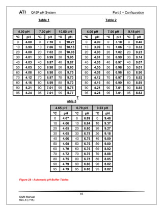
Auto Buffer This is a multiple variable function that allows the user to choose
which pH buffer sets that will be utilized in the 2-point calibration
mode. The Q45P contains 3 sets of built-in buffer tables with
compensation values ranging from 0 to 95 °C. During 2-point
calibration, the instrument will automatically identify which buffer is
being used and compensate for the value based on the built-in
tables. This allows very quick, highly accurate calibrations by the
user. The order in which the buffers are used during calibration is
unimportant, since the system automatically chooses the correct
buffer.
The default setting for this feature is OFF, which disables the auto-
recognition function. Press ENTER to change this setting. The
buffer table set options are: 1: [4/7/10], 2: [4/7/9.18], and 3:
[4.65/6.79/9.23]. See Figure 28 for buffer tables. Once the buffer
set is selected, press ENTER and the message Accepted! will be
displayed on the lower line.](https://image.slidesharecdn.com/q45p-2-wire-ph-transmitter-230608141209-3d24cdc6/85/Q45P-2-Wire-pH-Transmitter-pdf-45-320.jpg)
![ATI Q45P pH System Part 5 – Configuration
46
O&M Manual
Rev-X (7/15)
Iout#1 Mode This function sets analog output #1 to either track pH
(default) or enables the PID controller to operate on the pH
input. Press ENTER to initiate user entry mode, and the
entire value will flash. Use the UP arrow key to modify the
desired value; selections include 1-pH for pH tracking or 2-
PID for pH PID control. Press ENTER to store the new
value.
Temp Units This function sets the display units for temperature
measurement. Press ENTER to initiate user entry mode,
and the entire value will flash. Use the UP arrow key to
modify the desired display value. The choices are °F and
°C. Press ENTER to store the new value.
5.25 Control Menu [CONTROL]
The Control Menu contains all of the output control user settings:
Set PID 0% If the PID is enabled, this function sets the minimum and
Set PID 100% maximum controller end points. Unlike the standard 4-20
[Iout1=PID] mA output, the controller does not “scale” output values
across the endpoints. Rather, the endpoints determine
where the controller would normally force minimum or
maximum output in an attempt to recover the setpoint (even
though the controller can achieve 0% or 100% anywhere
within the range.)
If the 0% point is lower than the 100% point, then the
controller action will be “reverse” acting. That is, the output
of the controller will increase if the measured value is less
than the setpoint, and the output will decrease if the
measured value is larger than the setpoint. Flipping the
stored values in these points will reverse the action of the
controller to “direct” mode.
The entry value is limited to a value within the range
specified in “Set Range”, and the 0% and the 100% point
must be separated by at least 1% of this range Use the
LEFT arrow key to select the first digit to be modified. Then
use the UP and LEFT arrow keys to select the desired
numerical value. Press ENTER to store the new value.](https://image.slidesharecdn.com/q45p-2-wire-ph-transmitter-230608141209-3d24cdc6/85/Q45P-2-Wire-pH-Transmitter-pdf-47-320.jpg)
![ATI Q45P pH System Part 5 – Configuration
47
O&M Manual
Rev-X (7/15)
PID Setpnt The measured value which the controller is attempting to
[Iout1=PID] maintain by adjusting output value. It is the nature of the
PID controller that it never actually gets to the exact value
and stops. The controller is continually making smaller and
smaller adjustments as the measured value gets near the
setpoint.
PID Prop Proportional gain factor. The proportional gain value is a
[Iout1=PID] multiplier on the controller error (difference between
measured value and setpoint value.) Increasing this value
will make the controller more responsive.
PID Int Integral is the number of “repeats-per-minute” of the action
[Iout1=PID] of the controller. It is the number of times per minute that
the controller acts on the input error. At a setting of 2.0 rpm,
there are two repeats every minute. If the integral is set to
zero, a fixed offset value is added to the controller (manual
reset.) Increasing this value will make the controller more
responsive.
PID Deriv Derivative is a second order implementation of Integral, used
[Iout1=PID] to suppress “second-order” effects from process variables.
These variables may include items like pumps or mixers that
may have minor impacts on the measured value. The
derivative factor is rarely used in water treatment process,
and therefore, it is best in most cases to leave it at the
default value. Increasing this value will make the controller
more responsive.
Set 4 mA These functions set the main 4 and 20 mA current loop
Set 20 mA output points for the transmitter. The units displayed depend
[Iout1=pH] on the selection made in the CONFIG menu for Iout #1
Mode.
The value stored for the 4 mA point may be higher or lower
than the value stored for the 20 mA point. The entry values
are limited to values within the range specified in “Set
Range”, and the 4 mA and the 20 mA point must be
separated by at least 1% of this range Use the LEFT arrow
key to select the first digit to be modified. Then use the UP
and LEFT arrow keys to select the desired numerical value.
Press ENTER to store the new value.](https://image.slidesharecdn.com/q45p-2-wire-ph-transmitter-230608141209-3d24cdc6/85/Q45P-2-Wire-pH-Transmitter-pdf-48-320.jpg)
![ATI Q45P pH System Part 5 – Configuration
48
O&M Manual
Rev-X (7/15)
5.26 Diagnostics Menu [DIAG]
The diagnostics menu contains all of the user settings that are specific to the
system diagnostic functions, as well as functions that aid in troubleshooting
application problems.
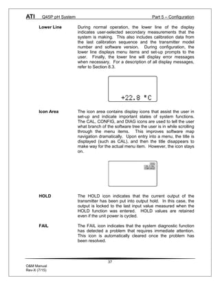
Set Hold The Set Hold function locks the current loop output values
on the present process value. This function can be used
prior to calibration, or when removing the sensor from the
process, to hold the output in a known state. Once HOLD is
released, the outputs return to their normal state of following
the process input. The transfer out of HOLD is bumpless on
the both analog outputs - that is, the transfer occurs in a
smooth manner rather than as an abrupt change. An icon
on the display indicates the HOLD state, and the HOLD state
is retained even if power is cycled. Press ENTER to initiate
user entry mode, and entire value will flash. Use the UP
arrow key to modify the desired value, selections are ON for
engaging the HOLD function, and OFF to disengage the
function. Press ENTER to store the new value.
The Set Hold function can also hold at an output value
specified by the user. To customize the hold value, first turn
the HOLD function on. Press the ESC key to go to the DIAG
Menu and scroll to Sim Output using the UP arrow key.
Press ENTER. Follow the instructions under Sim Output
(see following page).
Fault List The Fault List screen is a read-only screen that allows the
user to display the cause of the highest priority failure. The
screen indicates the number of faults present in the system
and a message detailing the highest priority fault present.
Note that some faults can result in multiple displayed failures
due to the high number of internal tests occurring. As faults
are corrected, they are immediately cleared.
Faults are not stored; therefore, they are immediately
removed if power is cycled. If the problem causing the faults
still exists, however, faults will be displayed again after
power is re-applied and a period of time elapses during
which the diagnostic system re-detects them. The exception
to this rule is the calibration failure. When a calibration fails,
no corrupt data is stored. Therefore, the system continues
to function normally on the data that was present before the
calibration was attempted.](https://image.slidesharecdn.com/q45p-2-wire-ph-transmitter-230608141209-3d24cdc6/85/Q45P-2-Wire-pH-Transmitter-pdf-49-320.jpg)
![ATI Q45P pH System Part 5 – Configuration
49
O&M Manual
Rev-X (7/15)
After 30 minutes or if power to the transmitter is cycled, the
failure for calibration will be cleared until calibration is
attempted again. If the problem still exists, the calibration
failure will re-occur. Press ENTER to initiate view of the
highest priority failure. The display will automatically return
to normal after a few seconds.
Sim Out The Sim Out function allows the user to simulate the pH
level of the instrument in the user selected display range.
The user enters a pH value directly onto the screen, and
the output responds as if it were actually receiving the signal
from the sensor. This allows the user to check the function
of attached monitoring equipment during set-up or
troubleshooting. Escaping this screen returns the unit to
normal operation. Press ENTER to initiate the user entry
mode, and the right-most digit of the value will flash. Use
arrow keys to modify desired value.
The starting display value will be the last read value of the
input. The output will be under control of the SIM screen
until the ESC key is pressed.
Note: If the HOLD function is engaged before the Sim Output
function is engaged, the simulated output will remain the
same even when the ESC key is pressed. Disengage the
HOLD function to return to normal output.
NOTE: If the HOLD function is engaged before the
Sim Output function is engaged, the simulated output
will remain the same even when the ESC key is pressed.
Disengage the HOLD function to return to normal
output.
Glass Diags This feature not for loop powered devices.
PID Timer This function sets a timer to monitor the amount of time the
[Iout1=PID] PID controller remains at 0% or 100%. This function only
appears if the PID controller is enabled. If the timer is set to
0000, the feature is effectively disabled. If the timer value is
set to any number other zero, a FAIL condition will occur if
the PID controller remains at 0% or 100% for the timer value.
If one of the relays are set to FAIL mode, this failure
condition can be signaled by a changing relay contact.](https://image.slidesharecdn.com/q45p-2-wire-ph-transmitter-230608141209-3d24cdc6/85/Q45P-2-Wire-pH-Transmitter-pdf-50-320.jpg)
![ATI Q45P pH System Part 6 – Calibration
55
O&M Manual
Rev-X (7/15)
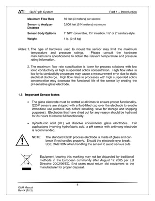
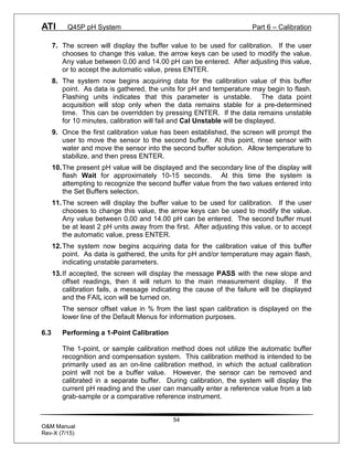
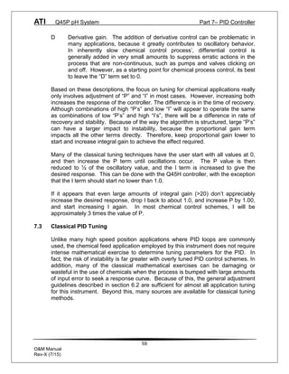
Procedure
1. Determine whether the calibration will be done on-line or with the sensor
removed and placed into a buffer. If the sensor is removed from the
application, rinse and clean if necessary.
2. If the sensor has been removed and placed into a buffer, allow sensor to
temperature equilibrate with the buffer as much as possible. With the sensor
coming from an application which differs greatly in temperature difference, the
user may have to wait as much as 20 minutes. If the sensor is on-line, the
user may want to set the output HOLD feature prior to calibration to lock out
any output fluctuations.
3. Scroll to the CAL menu section using the MENU key and press ENTER or the
UP arrow key. Cal pH will then be displayed.
4. Press the ENTER key. The screen will display a flashing 1 for 1-point or a 2
for 2-point calibration. Using the UP arrow key, set for a 1-point calibration
and press ENTER.
5. The system now begins acquiring data for the calibration value. As data is
gathered, the units for pH and temperature may flash. Flashing units indicate
that this parameter is unstable. The calibration data point acquisition will stop
only when the data remains stable for a pre-determined amount of time. This
can be overridden by pressing ENTER. If the data remains unstable for 10
minutes, the calibration will fail and the message Cal Unstable will be
displayed.
6. The screen will display the last measured pH value [or the auto buffer value, if
activated] and a message will be displayed prompting the user for the lab
value. The user must then modify the screen value with the arrow keys and
press ENTER. The system then performs the proper checks.
7. If accepted, the screen will display the message PASS with the new offset
reading, and then it will return to the main measurement display. If the
calibration fails, a message indicating the cause of the failure will be
displayed and the FAIL icon will be turned on.](https://image.slidesharecdn.com/q45p-2-wire-ph-transmitter-230608141209-3d24cdc6/85/Q45P-2-Wire-pH-Transmitter-pdf-56-320.jpg)

The document provides comprehensive details on the Q45P 2-wire pH transmitter, including product warranty, specifications, and operational instructions for installation, calibration, and maintenance. It outlines warranty terms, covering defects in materials and workmanship for specific periods, and describes the features and performance specifications of the Q45P and associated sensors. Additionally, it includes guidance on configuration, electrical installation, and troubleshooting to ensure optimal performance in various aqueous applications.


