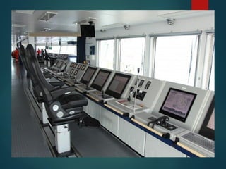
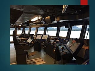
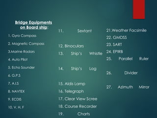
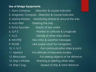
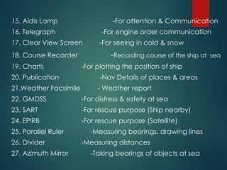
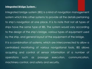
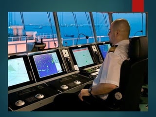
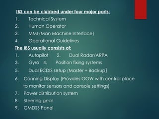
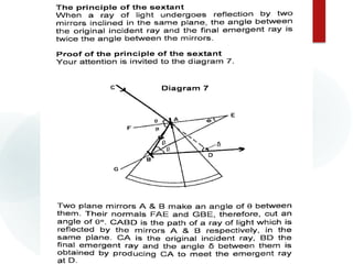
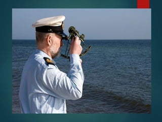
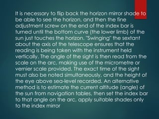
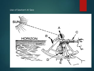
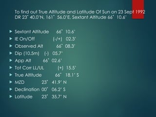
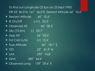
BRIDGE EQUIPMENT & WATCH KEEPING
Paper – I, SEM-III- SECTION A
Unit 1-
Lay out of Bridge and
Integrated Bridge
https://youtu.be/Bj3_peT4u9M
 Navigation Bridge and it’s Layout:
The bridge of a ship is the room or platform from which the
ship can be commanded/controlled. When a ship is
underway, the bridge is manned by an officer of the
watch aided usually by an able seaman acting as steering
man & lookout. During critical manoeuvres the captain will
be on the bridge, often supported by an officer of the
watch, an able seaman on the wheel, a look out and
sometimes a pilot, if required.
Today the bridge of a modem ship is totally enclosed by
glass screens or windows to give protection from cold, heat,
rain and wind. In addition to the steering wheel or steering
controls, the ship's main magnetic compass and a repeater
from the gyro compass are situated on the bridge. It also
houses a chart table, radar scanners and a rich array of
modem navigating and communication equipment.
The type and layout of the wheelhouse and the bridge,
as well as bridge wings, varies according to ship types
and to the changes in modem technology in
shipbuilding and navigation. Here is a layout of a
modem wheelhouse.
The bridge is the main control centre of a vessel, from
where the captain and officers are able to man the
entire operations of the vessel. It is generally located in
a position with an unrestricted view and immediate
access to the essential areas of a ship.
Types Of Bridge:
1- Normal Bridge
2- Integrated Bridge System(IBS)
3- Integrated Navigation System(INS)
Bridge Front
Main Bridge Inside with Equipments
After Side
Bridge Equipments
on Board ship:
1. Gyro Compass
2. Magnetic Compass
3.Marine Radars
4. Auto Pilot
5. Echo Sounder
6. G.P.S
7. A.I.S
8. NAVTEX
9. ECDIS
10. V. H. F
11. Sextant
12. Binoculars
13. Ship’s Whistle
14. Ship’s Log
15. Aldis Lamp
16. Telegraph
17. Clear View Scree
18. Course Recorder
19. Charts
21.Weather Facsimile
22. GMDSS
23. SART
24. EPIRB
25. Parallel Ruler
26. Divider
27. Azimuth Mirror
Use of Bridge Equipments
1. Gyro Compass -Direction & course indicator
2. Magnetic Compass -Direction & course indicator
3. Marine Radars -Monitoring ahead & around the ship
4. Auto Pilot -Steering the ship
5. Echo Sounder -Depth of sea water
6. G.P.S -Position in Latitude & Longitude
7. A.I.S -Details of other ships status
8. NAVTEX -Nav Infos & weather messages
9. ECDIS -Like paper chart for navigation
10. V. H. F -For communication ships & ports
11. Sextant -For altitude of heavenly bodies
12. Binoculars -For seeing objects at far distance
13. Ship’s Whistle -Warning or alerting other ships
14. Ship’s Log -Speed of ship & total distance
15. Aldis Lamp -For attention & Communication
16. Telegraph -For engine order communication
17. Clear View Screen -For seeing in cold & snow
18. Course Recorder -Recording course of the ship at sea
19. Charts -For plotting the position of ship
20. Publication -Nav Details of places & areas
21.Weather Facsimile - Weather report
22. GMDSS -For distress & safety at sea
23. SART -For rescue purpose (Ship nearby)
24. EPIRB -For rescue purpose (Satellite)
25. Parallel Ruler -Measuring bearings, drawing lines
26. Divider -Measuring distances
27. Azimuth Mirror -Taking bearings of objects at sea
Integrated Bridge System :
Integrated bridge system (IBS) is a kind of navigation management
system which links other systems to provide all the details pertaining
to ship’s navigation at one place. It is to note that not all types of
ships have the same type of IBS. The system would vary according
to the design of the ship’s bridge, various types of equipment used
by the ship, and general layout of the equipment of the bridge.
It is a combination of systems, which are interconnected to allow a
centralized monitoring of various navigational tools. IBS allows
acquiring and control of sensor information of a number of
operations such as passage execution, communication,
machinery control, and safety and security.
The IBS system should support two or more of the
following aspects:
 Execution of passage (Navigation)
 Communications
 Machinery control
 Cargo operations
 Safety and security
IBS is not mandatory on ships. Its installation and
design criteria is laid out by classification societies
such as the NAV1 class for LR, the W1-OC class from
DNC are examples of class arrangements for IBS.
Factors determining the layout includes bridge design,
type of equipment fitted and their positioning on the
bridge. IBS can be clubbed under four major parts:
IBS can be clubbed under four major parts:
1. Technical System
2. Human Operator
3. MMI (Man Machine Interface)
4. Operational Guidelines
The IBS usually consists of:
1. Autopilot 2. Dual Radar/ARPA
3. Gyro 4. Position fixing systems
5. Dual ECDIS setup (Master + Backup)
6. Conning Display (Provides OOW with central place
to monitor sensors and console settings)
7. Power distribution system
8. Steering gear
9. GMDSS Panel
Aim of Integrated Bridge System :
1. To promote safe & efficient management of the ship.
2. To reduce the workload of duty officer.
3. To provide centralised control.
4. To provide a recording unit (Voyage Data Recorder,
VDR).
5. To be capable of being operated by a qualified person.
6. Should be user friendly.
Advantages of Integrated Bridge System :
1. Centralized control.
2. All the parameters readily available which will help in
decision making at sea.
3. All equipments are well monitored, less chances of error.
4. Accuracy in navigation, thus time can be saved
5. Alarms for improper actions are available.
6. Better overall risk assessment & management.
7. Equipment built user friendly.
Disvantages of Integrated Bridge System :
1. Over rely on automation, as a result lethargy sets in.
2. Limitations of equipments should be kept in mind to avoid
dangerous situations.
3. Tendency to bypass the alarms, which may cause
dangerous / close quarter situations.
4. Reduction in man power, in emergency machine can not
replace man.
5. Different make systems may cause problems for pilots as
they can not learn in short time.
Integrated Navigation System: A system in which the
information from two or more navigation aids is combined in
a symbiotic manner to provide an output that is superior to
any one of the component aids.
Work stations situated at the main navigation console, chart
table and bridge wings are essentially identically built display-
control units on a single high-speed network. Each of the
navigational tasks can be carried out at any one of these
workstations:
1-Collision avoidance,
2-Route monitoring,
3-Route planning and alert management.
Every bit of navigation control data is seen at one place
without having to walk around to scattered display devices.
 Advantages of INS: The development in integrated
bridge system by
1-Integrating open design architecture
2-Combination of navigational equipment helps
in providing an efficient bridge design.
3-Improves safety,
4-Convenience,
5-Efficiency,
6-Flexibility of monitoring at real-time.
Difference between IBS & Integrated Navigation
System(INS)
 INS is a combination of navigational data and systems
interconnected to enhance safe navigation of the vessel.
IBS interconnects various other systems along with the INS
to increase overall management efficiency. It can be said
that the INS is specific while the IBS is general in approach.
 Though IBS is an excellent system for navigation, officers on
watch shouldn’t completely rely on the equipment but
should pay proper attention to visual navigational watch
keeping techniques as well.
 Also, proper guidelines should be provided on the bridge
manual as to when to use and when not to use the
Integrated Bridge System (IBS).
 Normal bridge has got bridge equipment located in
different parts of the bridge, but in IBS combined in
consoles.(Notes-1)
Unit: 2 Sextant
 A Sextant is a doubly reflecting navigation
instrument that measures the angular
distance between two visible objects.
 The primary use of a sextant is to measure the angle
between an astronomical object and
the horizon for the purposes of celestial navigation.
The estimation of this angle, the altitude, is known
as sighting or shooting the object, or taking a sight.
The angle, and the time when it was measured, can
be used to calculate a position line on a nautical or
aeronautical chart—for example, sighting
the Sun at noon or Polaris at night (in the Northern
Hemisphere) to estimate latitude.
 Sighting the height of a landmark can give a
measure of distance off and, held horizontally, a
sextant can measure angles between objects for
a position on a chart.
 A sextant can also be used to measure the lunar
distance between the moon and another celestial
object (such as a star or planet) in order to
determine Greenwich Mean Time and
hence longitude.
The sextant is an instrument used for measuring the angles
 Altitudes of celestial bodies
 (VSA)vertical sextant angles of terrestrial objects,
 (HAS) horizontal angles between terrestrial objects.
 It is so called because its arc is one sixth of a circle – 60
deg.
 Being an instrument of double reflection it can measure
angles up to 120 deg.
 In actual practice , the arc of the sextant is a little more
than 60 deg and is hence graduated up to 130 deg.
Horizon Glass
Index Glass
Telescope
Frame
Moving Arm
Shades
Handle
Arm (Rack)
Shades
Different Parts Of A Sextant
A sextant is shaped in the form of a sector (60 degrees or 1/6th of a
circle). It is the reason the navigational instrument is called a Sextant
(Latin word for 1/6th is Sextant). The sector-shaped part is called the
frame.
A horizontal mirror is attached to the frame, along with the index mirror,
shade glasses (sun shades), telescope, graduated scale and a
micrometre drum gauge.
Components of a sextant
The parts of a sextant may be grouped into three components
Mechanical components:
• A frame F fitted with a brass arc AC.
• An arm B, called the Index bar, pivoted at the geometric centre of the
arc.
• A spring-loaded disengaging clamp P, for large movements of the arm B.
Three legs, on the underside, for supporting the
sextant when placed on a table (not visible
indiagram 1).
• Handle N for holding the sextant during use.
 Release Clamp (P)
 Three legs, on the underside, for supporting the
sextant when placed on a table
 Handle N for Holding the Equipment
Principle of the Sextant
1-When a ray of light is reflected by a plane mirror,
the angle of the incident ray is equal to the angle
of the reflected ray, when the incident ray,
reflected ray and the normal lie on the same plane
2-When a ray of light suffers two successive
reflections in the same plane by two plane mirrors,
the angle between the incident ray and the
reflected ray is twice the angle between the mirrors
 Required to Prove : δ = 2θ
Proof:
Angle CAF = angle FAB = α and
Angle ABE = angle EBD = β
(Angles of Incidence and reflection)
 In triangle ABD, 2 α = 2β + δ (1)
(External angle = sum of internally opposite angles)
 In triangle ABE, α = β + θ
(External angle = sum of internally opposite angles)
 So 2 α = 2 β + 2 θ (2)
 Equation (1) = equation (2) as both = 2 α
 So 2 β + δ = 2 β + 2 θ and hence δ = 2θ.
 Reading On & Off the arc: The normal graduations of the arc, to the
left of zero, extending from 0 to 130 degrees are referred to as ON the
arc. To the right of 0 degrees, the graduations extend for few
degrees and are referred to as OFF the arc.
 Reading of a sextant reading:
1-Degrees are read directly from the graduated arc opposite the
index mark on the index arm.
2-Minutes are read from the micrometer drum opposite the Vernier
index mark.
3-Seconds are read from the vernier where one of the vernier
graduations lines up with one of the. micrometer graduations.
The normal graduations of the arc, to the left of zero, extending from 0
to 130 degrees are referred to as ON the arc. To the right of 0 degrees,
the graduations extend for few degrees and are referred to as OFF the
arc. When reading OFF the arc, graduations of the micrometre should
be read in the reverse direction (59 as 1’, 55 as 1’ and so on).
Errors of Sextant :
1- Errors adjustable on board ship
a. Error of Perpendicularity (Index Mirror)
b. Side Error (Horizon Mirror)
c. Error of Collimation (Telescope)
e. Index Error (Index Mirror & Horizon Mirror are not
parallel)
2. Errors not adjustable on board ship
a. Centring Error
b. Optical Error
c. Worm and Rack Error
Important Points on the use of sextant :
1-Always check the errors before use.
2-Focus the telescope while looking at the horizon and make
a mark on the circumference of the stem
3-During use, hold the sextant steady. For this, stand with feet
slightly apart for balance with hands holding the sextant
steady
4-While observing the altitude of a celestial body, remember
to swing the sextant to the other side, The body will appear to
move along the arc. Measure altitude at the lowest point on
this arc
5-Stand as close as practicable to the centreline of the ship
6-USe appropriate dark shades while observing the sun
7-If backlash error exists remember to rotate the micrometre in
one direction only
8-Altitudes of stars and planets should be taken during twilight.
9-Night time sextant observations should be avoided so
far as practicable. The strong moonlight gives the illusion
of a good horizon which is most probably false
10-While observing the HSA, set index at zero, look at the
object on the right through the telescope, gradually
swing the index around and finish while facing the object
on the left.
11-When measuring VSA, look at the top of the object,
set index at zero and look at the top of the object. VSA
= height of the object in meters X Tan VSA
Care and maintenance of a sextant
1-Do not put too much stress on the index bar when
grasping a sextant
2-Never touch the arc. It will get smeard.
3-Ensure that worm and rack are clean.
4-Coat worm and rack with Vaseline when not using it for too
long.
5-Mirrors, lenses and shades should be wiped clean with a
soft cloth.
6-After each use, gently wipe the index mirror, horizon glass.
7-Put it in the box when not using it.
8-Do not bump the sextant anywhere.
9-Avoid exposure to sunlight.
10-Keep sextant stowed away from direct sunlight, dampness,
heaters or blowers.
The sextant is an expensive, precision instrument which should
be handled with utmost care before and after use. This is used
as a secondary means of position fixing system at sea by
taking the sight of a heavenly bodies.
What is primary means of position fixing at coast & deep sea?
Taking a Sight
A sight (or measure) of the angle between the sun,
a star, or a planet, and the horizon is done with the
'star telescope' fitted to the sextant using a visible
horizon. On a vessel at sea even on misty days a sight
may be done from a low height above the water to give
a more definite, better horizon. Navigators hold the
sextant by its handle in the right hand, avoiding touching
the arc with the fingers. For a sun sight, a filter is used to
overcome the glare such as "shades" covering both
index mirror and the horizon mirror designed to prevent
eye damage. By setting the index bar to zero, the sun
can be viewed through the telescope. Releasing the
index bar (either by releasing a clamping screw, or on
modern instruments, using the quick-release button), the
image of the sun can be brought down to the level of
the horizon.
https://www.youtube.com/watch?v=7wKhsOQlmCY&t=2s
It is necessary to flip back the horizon mirror shade to
be able to see the horizon, and then the fine
adjustment screw on the end of the index bar is
turned until the bottom curve (the lower limb) of the
sun just touches the horizon. "Swinging" the sextant
about the axis of the telescope ensures that the
reading is being taken with the instrument held
vertically. The angle of the sight is then read from the
scale on the arc, making use of the micrometre or
vernier scale provided. The exact time of the sight
must also be noted simultaneously, and the height of
the eye above sea-level recorded. An alternative
method is to estimate the current altitude (angle) of
the sun from navigation tables, then set the index bar
to that angle on the arc, apply suitable shades only
to the index mirror
and point the instrument directly at the horizon,
sweeping it from side to side until a flash of the sun's
rays are seen in the telescope. Fine adjustments are
then made as above. This method is less likely to be
successful for sighting stars and planets.
Star and planet sights are normally taken
during nautical twilight at dawn or dusk, while both
the heavenly bodies and the sea horizon are visible.
There is no need to use shades or to distinguish the
lower limb as the body appears as a mere point in the
telescope. The moon can be sighted, but it appears
to move very fast, appears to have different sizes at
different times, and sometimes only the lower or upper
limb can be distinguished due to its phase.
Use of Sextant At Sea
To find out True Altitude and Latitude Of Sun on 23 Sept 1992
DR 23˚ 40.0’N, 161˚ 56.0’E, Sextant Altitude 66˚ 10.6’
 Sextant Altitude 66˚ 10.6’
 IE On/Off (-/+) 02.3’
 Observed Alt 66˚ 08.3’
 Dip (10.5m) (-) 05.7’
 App Alt 66˚ 02.6’
 Tot Corr LL/UL (+) 15.5’
 True Altitude 66˚ 18.1’ S
 MZD 23˚ 41.9’ N
 Declination 00˚ 06.2’ S
 Latitude 23˚ 35.7’ N
To find out Longitude Of Sun on 23 Sept 1992
DR 23˚ 40.0’N, 161˚ 56.0’E, Sextant Altitude 66˚ 10.6’
 Sextant Altitude 66˚ 10.6’
 IE On/Off (-/+) 02.3’
 Observed Alt 66˚ 08.3’
 Dip (10.5m) (-) 05.7’
 App Alt 66˚ 02.6’
 Tot Corr LL/UL (+) 15.5’
 True Altitude 66˚ 18.1’ S
 TZD 23˚ 41.9’ N
 LHA 290˚ 14.8’
 GHA 089˚ 44.4’
 Observed Long 159˚ 29.6’ E
Unit – 3,
MAGNETIC COMPASS
GYRO COMPASS
Magnetic Compass:
Earth’s Magnetism :Earth’s Magnetism is generated by
convection currents of molten iron and nickel in the earth’s
core. These currents carry streams of charged particles and
generate magnetic fields.
This magnetic field deflects ionizing charged particles
coming from the sun (called solar wind) and prevents them
from entering our atmosphere. Without this magnetic shield,
the solar wind could have slowly destroyed our atmosphere
preventing life on earth to exist. Mars does not have a
strong atmosphere that can sustain life because it does not
have a magnetic field protecting it.
 Magnetic Poles: The north and south poles of a magnet
were first defined by the Earth's magnetic field, not vice
versa, This practice was due to one of the first uses for a
magnet was as a compass needle. The depicted North
Magnetic Pole of the Earth is really the South pole of its
Magnetic field (the place where the field is directed
downward into the Earth). However Naming is done in
accordance with usual Geographical direction of North
and south.
 A magnet's North pole is defined as the pole that is
attracted by the Earth's North Magnetic Pole when the
magnet is suspended so it can turn freely. Since opposite
poles attract, considering Earth as a Giant Magnet,
Earth's magnetic north pole is actually the south pole of
Earth's geographic poles, and vice versa. Hence it seems
The magnetic north pole attracts the north magnetic
pole of other magnets, such as compass needles.
 The magnetic poles are near but not exactly in the
same places as the geographic poles. The direction of
Earth's magnetic field is from its southern hemisphere to
its northern hemisphere. The rotation of Earth around its
axis causes the core of the Earth to rotate, which
generates current and eventually the magnetic field.
 The positions of the magnetic poles can be defined in
at least two ways: locally or globally. The local
definition is the point where the magnetic field is
vertical. This can be determined by measuring the
inclination. The inclination of the Earth's field is 90°
(downwards) at the North Magnetic Pole and -90°
(upwards) at the South Magnetic Pole.
Magnetic Compass: The magnetic compass is fitted
on the upper bridge (Monkey Island), exactly on the
center line of the ship. It is referred to as the
standard compass because it is the primary means
of direction indication on board ship. There are two
basic types of compasses Cards :
1-Dry Card Compass
2-Wet Card compass
The Dry Compass Card: The compass card is made
of rice paper. This is very light & is not affected by
temperature changes. This paper is divided into
several segments and glued to each other and
connected to the aluminum ring at the edge by silk
threads.
 The directive element consists of three, four or five
pairs of thin cylindrical magnets arranged parallel
to each other in the N/S axis of the card a few
centimeters below the card. They are so arranged
that the longest pair is closest to the centre, such
that their ends form a circle. The method used
ensures that the centre of gravity of the entire card
assembly is below the tip of the pivot about which
the card is free to rotate.
The Wet Card Compass: As stated earlier wet card compass
is less sensitive to small disturbance and so more useful as a
steering compass, without any loss of accuracy.
 The Wet card is made of mica in one piece and the
graduations are printed on the edges. The card is attached
to a nickel silver float chamber, which has a sapphire cap at
the centre. The Cap rests on an iridium tipped pivot. Though
the weight of the wet card is considerable, the buoyancy of
the float chamber reduces the load on the pivot and allows
a frictionless rotation of the card.
 The directive element of the card is achieved by a ring
magnet fitted around the base of the float. In older type of
compasses, the directive element consisted of two
cylindrical bar magnets one on each side of the float
parallel to the North-South axis of the card.
Advantages of Wet compass over Dry Compass
Card
 The dry card compass is generally used as a standard
compass & the wet card compass as a steering
compass.
 The dry card compass is very sensitive. Even a slight
disturbance makes the dry card oscillate.
 In the wet card compass, the oscillation is damped in
the liquid and hence more useful as a steering
compass.
 In some ships, the wet compass is now used as a
standard compass, mainly because of the availability
of the gyro compass as the main direction indicating
instrument.
32-point Compass Card
The four primary directions of the compass;
the North, South, East, and West
Cardinal Directions
On the Traditional compass rose above,
only north is filled in.
Filled in the rest of the points on the
compass, going clockwise, using the
standard abbreviations.
Lubber line: A lubber line is a fixed line on compass
binnacle or radar plan position indicator display
pointing towards the front of the ship. The line
represents 000 degrees and is therefore the zero-
point from which relative bearings of targets are
measured. This also divides the ship into two parts
port & starboard.
The Binnacle:- The binnacle is a cylindrical container made
of teak wood and brass. No magnetic materials are used in
its construction. Even the screws are of brass and the nails,
copper. The compass bowl is slung inside the top portion of
the binnacle. The middle potion is accessible by a door
and contains an electric bulb. Light from this bulk passes
upwards through a slot, through an orange colored glass
fitted over the slot, through the bottom of the compass
bowl, to illuminate the compass card from below. The
orange color ensures that the night vision of the observer is
not adversely affected.
The lower part of the binnacle contains a number of holes
both in the fore and aft & athwart ship directions to
place corrector magnets at the time of compass
adjustment. The lower binnacle also has a brass vertical
tube at its centre. This tube carries a ‘bucket’ to introduce
vertical magnet to correct the heeling error. The bucket
can be raised or lowered by means of a brass chain, which
can be secured at the required height.
Corrector Magnets:- In the centre of the lower half of
the binnacle, there are a number of horizontal holes,
both fore & aft and athwart ships, for ‘hard iron’ or
‘permanent’ corrector magnets which are meant to
offset undesirable, disturbing, magnetic effects caused
by the ship’s steel hull. The lower two-thirds of the
binnacle has a vertical brass tube, at the centre, in
which slides a ‘bucket’. This bucket has some magnets
in it called ‘heeling error correctors’. The bucket is held
in position by a brass chain.
Flinders Bar:- This is a soft iron corrector, (diameter
about 7.5 to 10 cm) inserted in a 60 cm long brass case,
fitted vertically on the forward or on the after part of the
binnacle. If the ship has more superstructure abaft the
compass, the Flinders bar is fitted on the forward part of
the binnacle and vice versa.
 Quadrantal Correctors:- These are two ‘soft iron’
spheres which are fitted in brackets, one on either
side of the binnacle. The brackets are slotted so
that the distance between the spheres can be
altered as desired during compass adjustment.
 The position of these corrector magnets and the
soft iron correctors should not be altered except by
a qualified compass adjuster.
 The binnacle doors should always remain locked &
keys safely kept with master or a responsible officer
deputed by him. They are opened only during
compass adjustment.
A periscope tube arrangement consisting of lenses
and a mirror is usually fitted at the bottom of the
binnacle to view the compass card reading of the
magnetic compass. This is done to view the compass
reading inside the wheelhouse at the steering position.
Errors of Magnetic compass:
Magnetic Variation:
 Magnetic declination, sometimes called magnetic variation, is the
angle between magnetic north and true north.
 Declination is positive east of true north and negative when west.
Magnetic declination changes over time and with location.
Magnetic Deviation :
 The amount a magnetic compass needle is deflected by
magnetic material in the ship is called deviation.
 Although deviation remains a constant for any given compass
heading, it is not the same on all headings.
 As the ship goes through an entire 360° of swing Deviation
gradually increases, decreases and then on next cycle
increases, and decreases again.
 The standard compass provides a means for reference checking
by comparing the reading on the same and the gyrocompass.
Other Errors of Magnetic compass
Magnetic dip
When the Earth's magnetic field lines dip towards the center of the Earth near
the north and south magnetic poles, the compass needle may deviate from
north. This error is most noticeable when turning or accelerating or
decelerating, especially on north and south headings. For example, when
turning from north, the compass may indicate a turn in the opposite direction.
Acceleration/deceleration
In the Northern Hemisphere, as you accelerate, the compass may show a turn
to the North, and as you decelerate, it may show a turn to the South.
Turning error
When turning from a heading of east or west, the compass may lag behind or
lead ahead of the turn.
Oscillation
The compass card may move inside the compass fluid due to aircraft
maneuvers or turbulence.
Care & maintenance
 Doors giving access to corrector magnets should always
remain closed.
 Quadrantal correctors & their brackets should be painted to
prevent rust.
 Wooden parts of the binnacle should be varnished and not
painted, as painting may cause the doors to jam.
 Brass parts of the binnacle should be regularly polished.
 The binnacle light should be switched off at daytime & while
in port.
 All magnetic material & electric wires etc should be kept as
far as any from the compass as possible.
 The hood should always be in place except when the
compass is being used, Cover it again after use.
 Unship the azimuth mirror from magnetic compass when gyro
compass is used for bearings.
Gyro Compass: A Gyro compass is a form of gyroscope,
used widely on ships and works on electric power, a fast-
spinning gyroscope wheel and frictional forces among
other factors utilizing the basic physical laws, influences of
gravity and the Earth's rotation help to find the true north.
Gyrocompass is a navigational instrument which makes
use of a continuously driven gyroscope to accurately
seek the direction of true (geographic) north. It operates
by seeking an equilibrium direction under the combined
effects of the force of gravity and the daily rotation of
Earth.
A compass with a motorized gyroscope whose angular
momentum interacts with the force produced by the
earth's rotation to maintain a north-south orientation of
the gyroscopic spin axis, there by providing a stable
directional reference.
Basic Elements of Gyro Compass:
1-Gyroscopic inertia,
2-Precession
3-Earth's rotation
4-Gravity
Gyro Error: It is the difference between gyro bearing of an heavenly
body (Sun & Moon) taken with the help of azimuth mirror and True
bearing obtained by calculation. It is always denominated as High Or
Low
Gyro Error:
True Azimuth of sun (Calculated) - 251˚ T
Gyro Azimuth of sun (By bearing) - 250˚ G
Gyro Error - 1˚ low
Compass Error: It is the difference between True Gyro
bearing and Standard (Magnetic) Compass bearing. It is
always East or West.
True Azimuth – 050˚ T Gyro Compass
Compass Azimuth – 046˚ C Magnetic Compass
Compass Error - 04˚ E
Gyro Error and Compass Error are basically the same thing,
but on different types of compasses. Whenever going
away from True, you add West Errors and subtract East
Errors.
Azimuth Mirror: Used in conjunction with a compass, this
device enables the operator to take celestial and
terrestrial bearings of objects. By means of a mirror and a
lens, the azimuth mirror allows both the compass's cardinal
points (direction), and the 'object', to be seen at the same
time and in the same direction.
 Azimuth mirror is therefore portable
equipment which is placed over a magnetic or
gyro compass for measuring bearings of terrestrial
and celestial objects. Sight Vanes (Near vane & far
vane) Allow the observer to take bearings of
objects by aligning the two vanes to the object.
Azimuth circle: An azimuth circle consists of 360
degrees. Ninety degrees corresponds to east, 180
degrees is south, 270 degrees is west, and 360
degrees and 0 degrees mark north. The word
"bearing" is sometimes used interchangeably with
azimuth to mean the direction (the degree reading)
from one object to another.
Gyro Compass
Azimuth Mirror
(Circle)
Azimuth Mirror
UNIT: 4 STEERING CONTROL
SYSTEM
STEERING GEAR SYSTEM
A steering gear is the equipment provided on board ship to
turn the ship to port or stbd side while on motion during
sailing at sea. The gear works only when the ship is in motion.
All the ships are to be provided with an efficient main steering
gear, an auxiliary steering and except for very small, the main
steering should be power operated (standby)
Manually operated, mechanical steering gears were in use
during the sailing ships days. Sailors with strong body were
required to operate the steering gear. Later on, after the on
set of steam ships, mechanized gears were used. Modern
ships use very sophisticated steering gear system which could
come in either of following categories:
 Fully Hydraulic System
 Electro Hydraulic System
 Fully Electric System
Complete steering gear system consists of the three main parts
 Telemotor
 Control Unit
 Power Unit
1. Telemotor- It consists of two main parts namely, transmitter &
receiver. The transmitter Is located on the navigation bridge in the
form of a wheel, which transmits the given order to the receiver
unit located in steering compartment, by turning the steering
wheel. The receiver conveys this order to the control unit, also
located in the steering gear compartment via linear motion. The
telemotor is generally hydraulic type or it could also be electro
hydraulic type.
2. Control Unit- It is the link between the telemotor & the power unit.
It receives signals from the telemotor and operates the power unit
until it receives another signal, this time from the rudder through
the hunting gear to stop the operation of power unit.
3. Power Unit- This unit can be any prime mover, like steam pipe,
diesel engine or an electric motor, directly coupled to the rudder.
It can be an electric hydraulic or an all electric unit complete with
the telemotor.
Telemotor : Telemotor control is a hydraulic control
system employing a transmitter, a receiver, pipes and
a charging unit. The transmitter, which is built into
the steering wheel console, is located on the bridge
and the receiver is mounted on the steering gear.
Two rams are present in the transmitter which move in
opposite directions as the steering wheel is turned. The
fluid is therefore pumped down one pipe line and
drawn in from the other. The pumped fluid passes
through piping to the receiver and forces the
telemotor cylinder unit to move. The suction of fluid
from the opposite cylinder enables this movement to
take place.
The cylinder unit has a control spindle connected to it
by a pin. This control spindle operates the slipper ring
or swash plate of the variable delivery pump.
The steering gear provides a movement of the rudder in
response to a signal from the bridge. The total system
may be considered made up of three parts:
1-Control equipment.
2-Power unit.
3-Transmission to the rudder stock.
The control equipment conveys a signal of desired rudder
angle from the bridge and activates the power unit and
transmission system until the desired angle is reached.
The power unit provides the force, when required and
with immediate effect, to move the rudder to the desired
angle. The transmission system, the steering gear, is the
means by which the movement of the rudder is
accomplished.
Rudder position Indicator
Steering Control Panel
Steering Modes:
 Auto Steering (Auto Pilot)
 Hand Steering (With Steering wheel)
 Follow Up (With Joy stick like computer mouse)
 Non Follow Up (With Joy stick like computer mouse)
 Steering Control System: The controls provided on the
auto pilot control panel must be clearly under stood
and set by the officer of the watch, other wise the auto
pilot will not be able to steer a steady course, and the
steering gear system will be unnecessary overloaded
because of excessive helm orders.
 Operational Procedures: Auto pilot has got various
steering modes in its control panel, which can be
selected with the help of a selector switch.
Helm Orders and Internal Communications
Standard Marine Communication Phrases:
The IMO’s SMCP builds on a basic knowledge of the
English Language. It was drafted intentionally in a
simplified version of maritime English in order to
reduce grammatical, lexical and idiomatic varieties
to a tolerable minimum using standardized
structures for the sake of its function aspect i.e,
reducing misunderstanding in safety related verbal
communications, there by endeavoring to reflect
present maritime English language usage on board
ship-to-ship and ship-to-shore communications
Communication problems cause more accidents than
investigation reports record: They require root cause
analysis to acquire reliable data. Communicatively
relevant factors tend to be covered by more striking
"follow-up" events in the chain of causation, so that the
consequences are emphasized and recorded rather
than the root causes themselves, i.e. communication.
 A striking example is this: A Spanish speaking
motorman reported a developing fire in the engine
room during his watch and reported the incident
immediately to the bridge. The OOW ordered: “Close
all openings. Evacuate the engine room.” The
motorman understood “evacuate”, but didn’t catch
the meaning of “close all openings.” So he
abandoned the engine room leaving the skylights
open.
 The fire spread, it couldn’t be controlled, and the
vessel became a technical loss. This accident was
catalogued under “Fire” and not under
“Communication problems” where it actually
belonged to.
 The Standard Marine Communication Phrases (SMCP)
has been compiled: -
 to assist in the greater safety of navigation and of the
conduct of the ship, -
 to standardize the language used in communication
for navigation at sea, in port-approaches, in
waterways, harbors and on board vessels with
multilingual crews, and –
 to assist maritime training institutions in meeting the
objectives mentioned above.
 Further communicative features may be
summarized as follows:
1-Avoiding synonyms
2-Avoiding contracted forms
3-Providing fully worded answers to "yes/no"-
questions and basic alternative answers to
sentence questions
4-Providing one phrase for one event,
5-Structuring the corresponding phrases after the
principle identical invariable plus variable.
Purpose Of Standard Marime Communication Phrases:
1- To assist in the greater safety of navigation and
conduct of the ship
2- To standardize the language used in communication
for navigation at sea, in port approaches, water ways,
in harbors and on board ships with multi language
crew.
3- To assist maritime training institutions in meeting the
objectives mentioned above.
The SMCP meets the requirements of the STCW
Convention, 1978, as revised, and of the SOLAS
Convention, 1974, as revised, regarding verbal
communications; moreover, the phrases cover the
relevant communication safety aspects laid down in
these Conventions.
STEERING ORDERS/ HELM
ORDERS
The Helmsman and Helms Orders:
The Helm and Helmsman Duties never relieve the helm nor
should the helmsman surrender the helm when the vessel is
in a turn, and until the vessel has been steadied on the new
ordered course to steer. To relieve the helm and the
helmsman on watch, the following information should be
part of the pass down informations from the helmsman you
are relieving:
1-The ordered ship's course in true or magnetic, and the
compass or repeater that is being steered by.
2-If steering by gyro compass, what is the ordered true
course, what is the compass error, the gyro course to steer
true, and what is the magnetic compass checking course.
(The checking course is the equivalent course to steer by
magnetic compass if the gyro compass fails.)
3-Any steering peculiarity such as "Carrying a little right
rudder," or "Carrying mostly left.
4-Any received orders that are still standing, such as "Steer
Nothing to the Left," or "Steady on Course 090º ."
5-In restricted waters, is the ship being steered on a range,
landmark or light, make sure it is pointed out to you and you
are clear and sure that you recognize it.
6-What steering unit is engaged (Port or Starboard), and if the
standby steering unit is "off or in stand-by."
7-What is the condition of all helm equipment(steering
system).
8-What has the weather and sea state been.
9-Any special circumstances or instructions that helmsman
should know about.
Once ABs are ready to relieve the helm, first report to the
officer of the watch that they are ready to relieve the watch,
and request permission to relieve the helm. Wait for the
officer of the watch to acknowledge the report and gives
ABs permission to relieve the helm.
On some ships the routine is a bit more formal,
where a full report is required to be stated verbally
to the officer on watch by the person relieving the
helm, for example;
"Sir, request permission to relieve the helm, steering
course 100º true, 101º per gyro compass, checking
course is 106º , steering on the port steering,
starboard steering unit is in standby."
The officer on watch normally will acknowledge
and give permission to relieve the helm by stating
"very well" or "very well, relieve the helm or OK
relieve."
Helm Order Indicator
Rate of Turn Indicator :
It indicates the rate at which a ship is turning, it indicates the
rate a ship is turning degrees per minutes. It is one of the most
important instrument a OOW / helmsman will need in bridge
when steering. It is used to turn a ship at a steady rate of turn,
specially in pilotage waters.
Working of a Rate of Turn Indicator: The principle of the
rate of turn indicator is based on a gyroscope with an
availability of turning in just one direction. The indicator is fed
60-200 pulses per minute from the steering repeater & from
this input it will work out rate of turn. When the ship is steering
a straight course, the gyroscope will point in a straight
direction and the pointer will point to the zero on the display.
When the vessel makes a turn to port, the gyroscope will turn
to port due to inertia and this will be pointed on the display of
the rate of turn indicator, and same for the stbd side as well.
 Use of ROTI (Rate Of Turn Indicator):-
 The rate of turn indicator is equipment which indicates the
instantaneous rate at which the ship is turning.
 This indicator is fed 60 to 200 pulses per minute from
the steering repeater and from this input it works out the
instantaneous rate of turn.
 The dial is marked usually 0O
to 60O
on either side. As per IMO
performance standard the dial should be marked not less than
0O
to 30O
per minute on either side and graduated in intervals
of 1O
per minute.
 As when the ship turn she actually traverses some distance
round the arc of a circle and cannot execute a sharp turns
about a point.
 When ship is making a turn it precise the ship track uncertain
due to her characteristic, condition, weight and UKC.
 IMO recommends for passage planning is not only monitor the
position on straight course but also on curve section of
passage.
Helmsman on the steering wheel
 Helm Orders (Example-1)
OOW: (order) "Port fifteen"
Helmsman: (repeat)"Port fifteen"
Action - Applies 15˚ of port helm, once the rudder angle
indicator displays the ordered helm then report.
Helmsman: Report- “Fifteen of port wheel on, Sir"
OOW: (acknowledgement)"Very good"
(Example-2)
OOW: (order) “Starboard fifteen"
Helmsman: (repeat)”Starboard fifteen"
Action - Applies 15˚ of starboard helm, once the rudder angle
indicator displays the ordered helm then report.
Helmsman: Report- “Fifteen of starboard wheel on, Sir"
OOW: (acknowledgement)"Very good"
OOW: “Ease to five,”
Helmsman: “Ease to Five,” Slowly turns the wheel to 5° of port helm,
once the rudder angle indicator displays the ordered helm then
report.
Helmsman: “Five of Port wheel on Sir”
OOW: “Very Good,”
Example -3 Ordering Wheel Mid-ship
Mid-ship – Mid-ships is the order to bring the rudder to (000) Mid-ships
is used when an incorrect order or action is taken and is always
followed by either a Conning order, Helm order or the order Steady
the course
OOW: "Mid-ships"
Helmsman: "Mid-ships"
Helmsman: After bringing wheel to amid-ship report
"Wheel amid-ships, Sir"
OOW: "Very good, "
Example -4, Steadying the Wheel on New Course
OOW: "Mid-ships“
Helmsman: "Mid-ships"
Helmsman: "Wheel’s amidships, Sir"
OOW: "Very good, Steady“
Helmsman: “Steady, One Three Seven,”
OOW: “Very Good, Steer One Three Seven,”
Helmsman: “Steer One Three Seven,” Executes the order and
reports once the Ship is on course
Helmsman: “Course One Three Seven Sir,”
OOW: “Very Good,”
Example-5, Counter Helm : Counter Helm is a helm order
given in the opposite direction of a previous helm order to
stop the ship’s turning fast, this order is given several degrees
before the ship head reaches the desired course.
Example-6 (Altering a large course from 030˚ – to - 220˚
OOW: “starboard twenty"
Helmsman: “Starboard twenty"
Helmsman: “Twenty of starboard wheel on, Sir"
OOW: “Report every 10˚ passing of ship’s head”
Helmsman: “Report every 10˚ passing of ship’s head”
Helmsman: “ship’s passing 040˚, 050˚, 060˚ ….. So on, Sir/Ma’am"
OOW: “Very Good when ship’s head 200˚, wheel amidships”
Helmsman: "Mid-ships“
Helmsman: "Wheel’s amidships, Sir“
OOW: “Very Good, when ship head on 210˚, port ten,”
Helmsman: “Port ten,”
Helmsman: “Port ten wheel on Sir”
OOW: “Very Good,”
OOW: “Amid-ship, steer two two zero”
Helmsman: “Steer two two zero”
Helmsman:”After steadying the course 220, steering
course
two two zero sir ”
OOW: “Very good”
Passing Through a Cardinal Point
When the ship passes through a cardinal point the
helmsman makes a report. This can be done using the
Cardinal point or degrees.
Examples
Helmsman: “Ship’s Head Passing through South, 15 of Port
wheel on Sir,”
Helmsman: “Ship’s Head Passing through one eight zero,
15 of Port wheel on Sir”
OOW: Very Good
Compass
For Steering
Engine Orders
Example OOW: "Half ahead both engines"
QM/Helmsman: "Half ahead both engines.
QM: “Both engines half ahead, Sir“
OOW: "Very good“
OOW: " Starboard fifteen, Half ahead port, slow astern
starboard, "
QM: " Starboard fifteen, Half ahead port, slow astern
starboard, "
QM: " Fifteen of starboard wheel on, Port engine half
ahead,
starboard engine slow astern, Sir"
OOW: "Very good"
Example Speed Setting
OOW: “Set speed One Two”
Helmsman: “Set speed One Two”
Helmsman: “Speed One Two Ahead Set, Sir.”
OOW: “Check Telegraphs,”
QM: “Port Half ahead, starboard stopped, Sir”
OOW: “ Very Good”
Duties of Helmsman /Able Seaman/Quarter Master
 Shall be in possession of watch keeping/Steering
certificate
 To report duty 10mins before the Watch time to take
over from the relieving person.
 To be properly dressed/attired in his place of duty
 To be aware of steering system, Switching on/off steering
Motor, Change over from one mode to another.
 Shall obey and carry out the helms orders properly
 No other duty is to be taken during the watch
 To be well aware of emergency steering system &
procedure
 Shall be able to steer the ship in all modes
Methods of Calling the Master to the bridge:
The master can be called to the bridge by using the
following methods / ways
 By using intercom system
 By sending messenger (Helmsman or Lookout/Deck
Cadet)
 By calling on UHF hand sets (Walkie Talkie)
 Public Address System
 Calling on sound power telephone
 By Sounding General Alarm
 Voice Pipe
 Any other Communication system As agreed by the
master
Switch Over From Manual (Hand Steering) To Auto:
 Steer the vessel on hand until steady on course
 Keep the rudder a mid ship exactly
 Turn the auto pilot course setting pointer to the course to be
steered
 Adjust all auto pilot control as required
 Switch over to auto steering
 Switch on the off course alarm and set as required
Switch Over from Auto Pilot to Manual: This may be
done any time by putting the switch from auto pilot to
manual and the vessel can be steered by the hand steering.
The steering must be reverted to hand at least once in a
watch, and vessel steered for some time to ensure the
proper working of the auto pilot.
Testing of Steering Gear System: Steering gear system is to be tried
out (tested), before arrival and departure from a port or anchorage.
And to be checked / tried out for its operational status as follows:
 Using the two steering motors one by one (Port & stbd)
 Using two motors together
 Match the timings given as per required standard (from mid ship to
either side with one motor & with two motor)
 Testing the rudder angle in the bridge
 Test the steering system from main steering, auxiliary and emergency
positions
 Check the hydraulic system for any leak
 Synchronize the gyro repeater & clock
 Check communication system (internal, sound power & hand set)
 Ensure duty engineer & electrical officers are present during testing
 Make entry of the steering system testing in the bridge log book
 Ensure oil level in the hydraulic tank as required.
 Sem-III-D 09.11.2021
Emergency Steering System: Emergency
steering system is provided on board ship to
over come dangerous situations in case of
failure of main steering system in bridge. This
system is provided in the steering gear
compartment at the stern. All the navigating
officers, engineering officers and deck crew
are to be well familiarized with emergency
steering system and procedures.
Procedure for Emergency Steering: The following given
procedure is to be followed in case of steering gear failure in
bridge
 The procedure and diagram for operating emergency steering
system should be displayed in steering gear compartment and
in bridge
 Make announcement on the public address system about the
steering failure
 Concerned navigating officer, engineering officer and
helmsman to reach steering compartment
 Establish proper communication between bridge and
emergency steering compartment (Intercom, sound power,
UHF hand set)
 Ensure bridge steering system is off and system in steering
compartment is on
 Remove the safety pin at the manual operation wheel, so that
during normal operation the manual operation remains cut off
 Quickly check and align the gyro repeater with bridge gyro
 Report readiness of emergency steering in steering room
 Take orders from the bridge and steer the ship with the help
of steering wheel / pins
Emergency Drill: An emergency steering drill is to be
carried out at least once in every 3 months and to be
logged in the bridge (Mate’s log) and official log books. It
is consist of direct operation (emergency steering) from the
steering gear compartment by manual control. Steering is
to be directed by communication from the bridge to train
all the ship’s staff for proper operation of the system, so that
in case of an emergency situation ship’s control can be
regained as soon as possible, avoid close quarter situation
and grounding.
Unit : 7 AUTOMATIC PILOT
AUTOMATIC PILOT
The auto pilot Is basically used when a ship has to steer
a set course for a long duration without alteration of
course. Any deviation from the set course is controlled
electronically and automatically by the auto pilot. The
auto pilot compares the course to steer set by the
watch officer, with the vessel’s actual course as seen
from the gyro / magnetic compass and applies the
rudder correction to steer the correct course. Since the
vessel will behave differently in different weather
condition, it is very important to be able to adjust the
auto pilot for different weather conditions in the same
way as the helmsman would steer a ship in different
weather conditions.
Control Panel
Auto Pilot
Main Unit
Auto Pilot
Main Unit
 Working of Auto Pilot:-
 Course is selected by the course selector.
 Present heading is indicated by the compass.
 The output from the compass is fed to the comparator in the
control unit. The signal from the course selector is also fed to the
comparator.
 Difference between the two signals is causing the output error
signal detected by the comparator.
 Integrator and differentiator analyze the signal.
 The signals from the comparator, integrator and differentiator are
fed to summing amplifier (control unit).
 The summing amplifier in turn, passes the signals to error amplifier
 The output of error amplifier is transmitted to steering gear via
telemotor transmitter and telemotor receiver.
 The steering gear is activated and turn the rudder as per the
required rudder angle.
 A feed back sent to error amplifier and rudder angle indicator
which displays the amount of rudder angle.
 The Autopilot Control Unit –
 The PID Control Unit:- In order to maintain the ship’s
course accurately, the deviation signal has to be
generated under the following conditions.
1-When the set course is changed (by the navigator).
2-When the ship deviates from the set course (due to
external factors).
 This is achieved by electronic circuits with the help of
the following:
1-Proportional control
2-Derivative control
3-Integral control
1-Proportional Control:-
 The effect on steering, when only the proportional control is
applied, causes the rudder to move by an amount proportional
to the off-course error from the course to steer.
 When the ship has gone off-course to port, an error occurs
which generate error signal, and helm proportional to the
deviation is used to bring her back to the set course.
 As the ship starts to return to the set course, the error signal is
gradually reduce the helm is eased accordingly and finally
removed when the ship is back on the set course.
 The rudder will be amidships when the ship reaches its set course
and then the heading overshoots resulting in the vessel to go
more to starboard. Correcting helm is now applied causing the
ship to return to port and back to the original course.
 The vessel thus keeps on oscillating to port and starboard of the
course line.
2-Derivative Control:-
 In derivative control, the rudder is shifted by an amount
proportional to the rate of change of the ship’s deviation
from the course. Any deviation of course to port will cause
correcting rudder to be applied to starboard.
 As the rate of change of course decreases, the automatic
rudder control decreases and at a point the rudder will return
to mid ships before the vessel reaches its set course.
 The ship will now make good a course parallel to the required
course.
3-Integral Control:-
 Certain errors due to the design of the ship (bow going to port
due to transverse thrust, shape of the hull, current draft, etc.)
have an impact on the steering capabilities of the ship and
have to be corrected for effective overall steering
performance.
The settings of an autopilot system are as follows:
 Permanent helm: To be used only if a constant influence, like
cross wind or beam sea is experienced. If there is a very
strong beam wind from starboard side then a permanent 5
degrees starboard helm may be set.
 Rudder: This setting determines the rudder to be given for
each degree of course drifted. Eg. 2 degrees for every 1
degree off course.
 Counter rudder: Determines the amount of counter rudder to
be given once v/l has started swinging towards correct
course to stop swing. Both rudder & counter rudder to be set
after considering condition of v/l (ballast, loaded, etc.). Eg.
Laden condition full ahead, not advisable to go over 10
degrees rudder.
 Weather: The effect of weather & sea conditions effectively
counteracted by use of this control. This setting increases the
dead band width. Comes in handy if vessel is yawing
excessively.
 Alarms of Auto Pilot:
1-Power Failure alarm
2-Off course Alarm
Off Course Alarm: An off-course alarm serves for the
purpose of notifying the operator if there is any difference
in the set course and the actual heading of the vessel. The
user can manually set the required amount of degrees,
after which an alarm will sound to notify the user that the
set degree of difference has exceeded.
An audible and visible alarm is activated at the steering
position whenever the vessel deviates from a chosen
course by more than a preset amount (in degrees).
Testing: Just simply turn your autopilot heading knob more
than the preset margin of your off course alarm. When it
reaches that heading the alarm should sound.
Off Course Alarm: Usually an Off Course Alarm is fitted on
the Autopilot. This can be set for the required amount of
degrees. So that if at anytime the difference between the
actual course and the Autopilot set course is more than the
preset degrees, an alarm will warn the officer.
 There is however, one limitation which should be noted. In
case, the gyro compass itself begins to wander the
Autopilot well steer so as to follow the wandering compass
and the Off Course Alarm will not sound. It does not ring
unless the difference between the course setting and gyro
heading is more than the preset limit.
 Rudder Limit:- This setting specifies the maximum amount of
rudder to be used when correcting the ship’s head or
when altering course on autopilot. That is, if a setting of
10O
is applied for rudder limit, when altering course the
rudder will move to a maximum of 10O
. This limit can be
varied according to the requirements of the navigator.
Functions Of Autopilot: An autopilot is a mechanical,
electrical or hydraulic system which can maintain a vessel
on a predetermined (set) course without the need of human
intervention. The auto pilot is not to take the place of the
navigation watch officer or helmsman in bridge.
1-It is to be used at open sea for long courses / long duration.
2-It is not to be used for large course alteration (up to 20°).
3-Autopilot is a course keeper and not changer.
4-Auto pilot is to be used when ship’s speed is more than 5
knots.
5-In case of engine failure, autopilot not to be used.
6-It is not to be used in narrow channel and congested
waters.
7-Not to be used in heavy traffic areas and in restricted
visibility.
The below notes are a brief outline of 10 important points to
be considered while operating Auto-pilot system onboard
ship for safe and smooth navigation.
 1. Rate of Turn and Rudder Limits (When altering course).
 2. Steering Gear Pumps (Change over, oil level in the tank).
 3. Off Course Alarm (Set as required).
 4. Manual Mode (For hand steering)
 5. Traffic Density (Use hand steering)
 6. Speed (Auto-pilot is not effective in speed less than 5
kts).
 7. Weather Conditions (Hand steering in rough weather)
 8. Gyro Compass (To be checked for error)
 9. Important Alarms and signals (Off course alarm to be on)
 10. Important Limitations (it is a course keeper not changer)
Rate of Turn
Indicator(ROTI) :
Rate of Turn Indicator :
It indicates the rate at which a ship is turning, it indicates the
rate a ship is turning degrees per minutes. It is one of the most
important instrument a OOW / helmsman will need in bridge
when steering. It is used to turn a ship at a steady rate of turn,
specially in pilotage waters.
Working of a Rate of Turn Indicator: The principle of the
rate of turn indicator is based on a gyroscope with an
availability of turning in just one direction. The indicator is fed
60-200 pulses per minute from the steering repeater & from
this input it will work out rate of turn. When the ship is steering
a straight course, the gyroscope will point in a straight
direction and the pointer will point to the zero on the display.
When the vessel makes a turn to port, the gyroscope will turn
to port due to inertia and this will be pointed on the display of
the rate of turn indicator, and same for the stbd side as well.
 Use of ROTI (Rate Of Turn Indicator):-
 The rate of turn indicator is equipment which indicates the
instantaneous rate at which the ship is turning.
 This indicator is fed 60 to 200 pulses per minute from
the steering repeater and from this input it works out the
instantaneous rate of turn.
 The dial is marked usually 0O
to 60O
on either side. As per IMO
performance standard the dial should be marked not less than
0O
to 30O
per minute on either side and graduated in intervals
of 1O
per minute.
 As when the ship turn she actually traverses some distance
round the arc of a circle and cannot execute a sharp turns
about a point.
 When ship is making a turn it precise the ship track uncertain
due to her characteristic, condition, weight and UKC.
 IMO recommends for passage planning is not only monitor the
position on straight course but also on curve section of
passage.
Adaptive Autopilot: This is an advance version of the
auto-pilot, which adapts to the steering capabilities
of the ship as well as the wind and weather
conditions.
An adaptive autopilot automatically adjusts the
sensitivity of a ship's steering system to
accommodate changes in speed as well as sea
and wind conditions. The autopilot utilizes heading
error, speed and speed squared signals to produce
a rudder order signal for controlling rudder position.
Depending upon the selected mode of operation,
Adaptive Steering Module (ASM) will perform the
following functions:
1-Open Sea Course Keeping.
2-Confined Water Course Keeping.
3-Course Changing.
Ship safety, stability of control, and adaptation to ship
speed are dominant factors in the total design of the
ASM. Additionally, criteria for minimum fuel
consumption and self adaptation to ship and sea
‐
conditions are factors in the design for Open Sea
Course Keeping.
Bridge Poster (Wheel House Poster):
- Wheel House Poster - The wheelhouse poster should
be permanently displayed in the wheelhouse. It should contain
general particulars and detailed information describing the
manoeuvring characteristics of the ship,
- It gives the following information, which are very important for the
officer of the watch to know the characteristics of his vessel when on
duty in bridge.
 Details of the ship, Name, Call Sign, GT, NT, Max Displacement, DWT,
Cb, Summer draft & Full load
 Steering particulars (Type of rudders & steering system)
 Anchor chain details
 Propulsion details (Type of propeller-fixed pitch or CPP)
 Thrusters & their Effect
 Draft increase / decrease (loaded / ballast)- TPC
 Turning Circle & Max Rudder Angle
 Visibility
 Man over board rescue manoeuvre
 Manoeuvring Characteristics
 - Inherent dynamic stability - A ship is dynamically stable on
a straight course if it, after a small disturbance, soon will
settle on a new straight course without any corrective
rudder action. The resultant deviation from the original
heading will depend on the degree of inherent stability and
on the magnitude and duration of the disturbance.
 - Course-keeping ability – The course-keeping quality is a
measure of the ability of the steered ship to maintain a
straight path in a predetermined course direction without
excessive oscillations of rudder or heading. In most cases,
reasonable course control is still possible where there exists
an inherent dynamic instability of limited magnitude.
 - Initial turning/course-changing ability – The initial turning
ability is defined by the change-of-heading response to a
moderate helm, in terms of heading deviation per unit
distance sailed or in terms of the distance covered before
realizing a certain heading deviation
 - Yaw checking ability – The yaw checking ability of
the ship is a measure of the response to counter-
rudder applied in a certain state of turning, such as
the heading overshoot reached before the yawing
tendency has been cancelled by the counter-rudder
in a standard zig-zag manoeuvre.
 - Turning ability – Turning ability is the measure of the
ability to turn the ship using hard over rudder. The
result being a minimum “advance at 90° change of
heading” and “tactical diameter” defined by the
“transfer at 180° change of heading”.
 - Stopping ability – Stopping ability is measured by
the “track reach” and “time to dead in water”
realized in a stop engine-full astern manoeuvre
performed after a steady approach at full test speed.
Other Manuals on bridge.
- Pilot card – The pilot card is intended to provide
information to the pilot on boarding the ship. This
information should describe the current condition of
the ship, with regard to its loading, propulsion and
manoeuvring equipment.
- Manoeuvring booklet – The manoeuvring booklet
should be available on board and should contain
comprehensive details of the ship manoeuvring
characteristics and other relevant data.
COURSE RECORDER
Course Recorder:
The course recorder is a navigational equipment for automatically
recording the course of a ship over a period of time, when the ship is
sailing. The recording is done on a paper roll continuously. The course
recorder is interfaced with gyro, speed log & magnetic compass.
Working Of Course Recorder: The signal from the gyro compass
giving the ship’s heading is fed & amplified, which derives the drum
servo motor ‘A’ in the direction indicated. The drum consists of two
sections, one with a continuous zigzag groove cut in it, going round
the drum ‘B’ and other with a stepped groove running round drum
‘C’
There is also a guide bar horizontal with a slit in it ‘D’ through which
the pens are fitted & run. On getting a signal from gyro the
servomotor rotates & turns the drum. The course pen moves along
the zigzag groove across the paper.
Input to the Course Recorder:
1. Gyro Feeding
(a) Ship’s heading
(b) Clock feeding
(c) Speed log
2. Recording Paper & Stylus
(a) Course section
(b) Time scale section
(c) Zone section
Care & Checks of Course Recorder : (Features)
 Lubrication of all the moving parts
 Check for correct recording of time, course & zone
 On arrival port to be switched off
 Before departure to be checked & tested, and set for use
 Keep paper roll stand by on sighting red line
 Keep replaced paper with start & end dates clearly marked for 2 years
Starting of Course Recorder:
 Set time scale, course section & zone section
 Adjust paper in its proper slots
 After adjusting keep it in standby state
 Switch on once ship’s movement commences
 Mark starting date & GMT time, with signature of OOW
Changing Of Recording Paper:
 Once red marking appears keep the paper roll standby
 Once thick red line appears, keep it in standby state
 Remove glass cover / window
 Take out old paper roll & replace with the new one
 Set time, course & zone as required
 Switch on once all the settings are done
Unit: 5 SPEED LOG
SPEED LOG : It is used to measure the speed of
a vessel in the water. The speed is determined with
reference to water flowing by the hull (water
reference speed) or to the seabed (ground
reference speed). It is important to note that the
speed measured by the log is through the water
and not over the ground. Log speeds are affected
by current and tidal streams.
Speed logs, also known as ship logs or common
logs, to measure the speed of a vessel. Such
equipment is referred to as a log due to the
obsolete practice of using wood logs for detecting
how fast a ship is moving.
An old sailing day’s log for
measuring the speed of a vessel
Origin of the term knot
Chip Log
THE DIFFERENCE BETWEEN SPEED THROUGH WATER AND SPEED
THROUGH GROUND IS AS FOLLOWS:
Speed through water (STW): It is the speed of a vessel in relation
to the water in which it is moving. It is measured by instruments
such as paddle wheel logs, pitot tubes, and Doppler logs. STW is
important for navigational purposes as it determines the time of
arrival at a destination and the amount of fuel required to cover
a certain distance.
Speed over ground (SOG): It is the speed of a vessel in relation
to a fixed point on the Earth’s surface, usually measured by GPS.
SOG takes into account the effect of currents, wind, and other
environmental factors on the vessel’s movement. It is the actual
speed at which a vessel is moving and is important for
determining the vessel’s position and course.
The main differences between STW and SOG are:
Currents: STW is affected by the currents of water in which
the vessel is moving, whereas SOG takes into account the
effect of ocean currents on the vessel’s movement.
Wind: STW is affected by the wind’s effect on the water,
whereas SOG takes into account the wind’s effect on the
vessel’s movement.
Navigation: STW is important for navigational purposes,
such as determining the time of arrival at a destination
and fuel consumption. SOG is important for determining
the risk of collision and vessel’s actual speed and
position.
w
0800
0900
0900
1000
Types of Logs :
 ELECTROMAGNETIC (EM)
 PITOMETER
 DOPPLER
 IMPELLER
 GLOBAL POSITIONING SATELLITE (GPS)
1- Electromagnetic Log : This log works on the
principle that if any conductor cuts a magnetic field,
a small EMF will be induced within itself which is
proportional to the speed of movement of the
conductor. In the case of this log, the conductor is
the sea water, the magnetic field is created by a coil
in the tube and the induced EMF is measured by two
sensors on the side of the tube.
Since sea water is a conductor of electricity, when it cuts
through the magnetic field of the coil in the tube, a small
voltage will be induced which is measured by two sensors
(electrodes) on the sides of the tube. This induced voltage is
proportional to the speed of the ship through the water. The
speed integrated with time to display distance.
2. Doppler Log : Doppler log is based on the principle of
Doppler shift in frequency measurement ie, apparent change
in frequency received when the distance between source and
observer is changing due to the motion of either source of
observer or both. In Doppler log an observer is moving with a
source of sound towards a reflecting plane, then the received
frequency by measuring the received frequency and knowing
the value of transmitted frequency and velocity of sound in
seawater, the speed of the vessel can be determined.
fr = Recived frequency
ft = transmitted frequency
c = velocity of sound in seawater
v = velocity of the vessel,
fr = ft {c+ ( v cos a) / c-(v cos a)}
By measuring the received frequency & knowing the
value of transmitted frequency and velocity of sound in
sea water, the
the speed of the vessel can be determined.
Principle Of Doppler Log : A transducer is fitted on
the ship’s keel which transmits a beam of acoustic wave
at an angle alpha usually 60 deg to the keel in the
forward direction, this gives the component c cos alpha
of the ship’s velocity towards the sea bed thus causing
the Doppler shift and the frequency
Working Of Doppler Log : A transducer is fitted on the ship’s keel which
transmits a beam of the acoustic wave at an angle usually 60° to the
keel in the forward direction. The beam is bounced off the seabed or
layer of the water and received back at the transducer. The
difference in frequency between the transmitted and received signals
is measured and is proportional to the speed of the ship.
Janus Configuration-
In practice the ship has some vertical motion and the Doppler shift
measurement will have a component of this vertical motion.
This problem is overcome by installing two transducers, one
transmitting in the forward direction and another in the aft direction at
the same angle. This arrangement is known as Janus configuration.
Athwart Ship Speed . The unique feature of some of the Doppler log is
to provide athwart ship speed over ground, which was never possible
by any other logs. To measure the athwart ship speed, additional
transducers are employed. These are called dual axis speed logs. The
introduction of Doppler log has brought about a tremendous change
in the outlook and approach of Masters and officers at sea. Safety of
navigation can be improved considerably if all ships were equipped
with an operational Doppler log. Sem-III A & B 05.10.2021
Navigators who never looked at nor had any respect for the
speed indicated by older logs are using accurate speed and
drift indicated by Doppler to their advantage in all their
manoeuvres. Safety of navigation can be improved
considerably if all ships were equipped with an operational
Doppler log.
IMO Requirements for Doppler log
 IMO resolution A.824 (19) as amended by MSC 96(72) gives the
details of the performance standards for the Doppler logs
fitted on ships.
 The device measuring speed and distance through the water
should meet the performance standard in water of depth
greater than 3 m beneath the keel
 Error in the measured and indicated speed for a digital display
should not exceed 2% of the speed of the ship, or 0.2 knots,
which is greater. For analogue display the error should not
exceed 2.5% of the speed of the ship or 0.25 knots whichever is
greater.
 The performance of the equipment should be such
that it will meet the requirements of performance
standards when the ship is rolling up to 10 degrees
and pitching up to 5 degrees.
Errors of the Doppler log
 Error in transducer orientation: The transducers
should make a perfect angle of 60° with respect to
the keel or else the speed indicated will be
inaccurate.
 Errors in oscillator frequency: The frequency
generated by the oscillator must be accurate and
constant, any deviation in the frequency will result
in the speed indicated being in error.
 Error in propagation velocity of the acoustic wave: The
velocity of the acoustic wave at the temperature of 16°c
and salinity of 3.4% is 1505m/sec, but generally it is taken
as 1500m/sec for calculation. This velocity changes with
temperature, salinity or pressure.
 Errors due to ship’s motion: during the interval between
transmission and reception, the ship may marginally roll or
pitch and thereby the angle of transmission and reception
can change and for a two degree difference between
the angle of transmission and reception, the net effect will
be an error of 0.10% of the indicated speed which is
marginal and can be neglected.
 Errors due to the effect of rolling and pitching: The effect of
pitching will cause an error in the forward speed, but it has
no effect on the athwart ship speed. Similarly, rolling will
cause an error in athwart ship, but not in forward speed.
 Errors due to inaccuracy in the measurement of
comparison frequency: The difference in the
frequencies received by the forward and aft
transducers must be measured accurately as any
error in this will be directly reflected in the speed of
the vessel.
 Error due to side lobe: When the side lobe reception
dominates over the main beam reception, there will
be an error in the speed indicated. This error is more
pronounced on a sloppy bottom, where the side
lobe will be reflected at a more favourable angle
and will have path length less than the main beam.
w
Unit: 6 ECHO SOUNDER
ECHO SOUNDER: Is the equipment used to measure the
UNDER KEEL CLEARENCE( depth from ship’s bottom( Keel)
to the sea bed) The echo sounder works on the principle
of measuring the time taken by a sound wave to travel
from the ship’s bottom (keel) to the sea bed and back
again. The equipment transmits the signal, detect the
echo and measures the elapsed time interval and thus
gives the depth of water.
Working of Echo Sounder: In the water under the ship,
short pulses of sound vibration are transmitted through
the transmitter at the rate of 5-600 pulses per minute to
the bottom of the sea. The sea bed reflects those pulses
and after a time which depends up on the depth of
water the echo pulse is received back by the receiver at
the ship. During this time, the pulse has travelled a path
equal to two time the distance between the keel of the
ship and the sea bed.
Principle Of Echo Sounder
 It works on the principle of transmitting sound waves from
ship’s bottom and then measuring the time taken for the
echo to be returned from sea bed. If the velocity of sound in
water is known the time will be proportional to the distance
travelled.
 The time taken by the waves to travel to and from the
seabed is measured and depth can be determined, by the
formula Distance=Velocity x Time/2
The depth of water is checked from the echo sounder just as a
matter of routine to see that the depth obtained matches with
that show on the chart. However when the position is not
accurately known while approaching the port, or crossing over
a bar, or near the mouth of a river, or in a poorly surveyed area,
the under-keel clearance and depth of water needs to be
known. The echo sounder comes in handy in such situation.
w
Controls Of Echo Sounder:
 Range selector switch
 Feet / meter / fathom selector switch
 Paper speed control switch
 Fix marker
 Draught setting
 Gain / sensitivity switch
 Panel dimmer control
Errors of Echo Sounder:
 Velocity of pulse error
 Error due to aeration
 Turbulence error
 Error due to pitching of the vessel
 Error due to rolling.
 Error due to bad weather
 Multiple echoes
 Error due to list and trim
 Error due to false bottom
Ranging: In echo sounder the stylus is rotating with
certain constant speed and the transmission takes place
as the stylus passes the zero mark. When the higher range
scale is selected, the transmission will still take place when
the stylus comes to zero, but the stylus speed is reduced
because the stylus has to remain on the paper for the
longer period of time, since the echoes are returning from
greater depth.
In Ranging the range scales are as given below
0-50, 0-100, 0-200, 0-300, 0-400, 0-500 mtrs & so on
Phasing: In this the speed of the stylus is kept constant, but
the transmission point is advanced, the sensors are
positioned around the stylus belt and stylus is rotating at a
fixed speed. A magnet mounted on the belt generates the
pulse when it passes the sensor, which in turn activates the
transmitter. When the range is less sensor 1 is used and
when the range is higher sensor 2 is used.
 In phasing the range scales are as given below
0-100, 100-200, 200-300, 300-400, 400-500 mtrs and so on
Ranging & Phasing: In some echo sounding system the
ranging and phasing arrangements are used in
combination, thus such system is known as phased ranging.
On such system the range scales are
0-100, 100-200, 200-400, 400-800 mtrs and so on
Operation and Use Of Echo Sounder :
 Switch on during arrival, departure port and when required
 Select appropriate range scale
 Select feet / meter / fathom as appropriate
 Mark the date, time of starting and sign
 Match the reading with the digital read out
 Log the depths in the echo sounder log specially arrival and
departure port
 Monitor the alarms which are set for particular depth
 Keep the old paper with proper start & stop dates
 Check the echo sounder before departure for its operational
status
 Lubricate all the moving parts frequently.
Maintenance of Echo Sounder:
 The speed of the stylus must be checked and adjusted
 Carbon from the stylus must be cleaned regularly
 Moving parts are to be lubricated as & when required
 Depth accuracy must be checked with the hand lead line
during port stay of the vessel
 During dry docking the transducer area should not be painted
 During dry docking the servicing of the transducer is to be
carried out
 Replaced paper is to be kept with start & stop dates and
signatures of the OOW.
 It is not to be used in higher depths
 Record of switch on, off and depth noted to be maintained
during arrival and departure port.
 Change the paper roll once thick red line starts appearing
Unit : 8 OTHER EQUIPMENTS
IN THE WHEEL HOUSE
Other Equipments In The Wheel House:
9.1, Chronometer: The chronometer is an accurate
time keeping instrument carried on board ship. It is
required for taking exact time of GMT when calculating
the astronomical sight for fixing the position of the vessel
at sea. The face of the chronometer is similar to that of
an ordinary clock, except for two additional dials inset
on the main dial. The first one contains the second hand
and hence is graduated from 0—60 seconds, the
second small dial has a pointer showing the number of
hours elapsed since the chronometer was last wound.
 Types Of Chronometers : There are two main types
of Chronometers used on board ships
 Spring Tension Type
 Quartz Crystal Type
Spring Driven Chronometer: The spring-driven marine
chronometer is a precision timepiece used aboard ship to
provide accurate time for celestial observations. A
chronometer differs from a spring-driven watch principally in
that it contains a variable lever device to maintain even
pressure on the mainspring, and a special balance designed
to compensate for temperature variations. A spring-driven
chronometer is set approximately to Greenwich mean time
(GMT) and is not reset until the instrument is overhauled and
cleaned, usually at three-year intervals.
Quartz crystal marine chronometers: Quartz crystal have
replaced spring-driven chronometers aboard many ships
because of their greater accuracy. They are maintained on
GMT directly from radio time signals. This eliminates
chronometer error (CE) corrections. Should the second hand
be in error by a readable amount, it can be reset electrically.
w
w
 Chronometer Error : No chronometer is expected to keep
perfect time. But if a chronometer gains or loses the same
amount each day, it has a constant daily rate. It is suitable
for navigation , because the precise value of the
chronometer error at any instant can be obtained by simple
extrapolation. The chronometer error is noted each day at
sea by means of radio time signals and the error noted in the
chronometer error log book.
 The Admiralty List of Radio Signal Volume – V gives details of
radio time signals available.
The daily rate should be small but if it is excessive, the chrono
meter should be sent ashore at the earliest opportunity to a
recognized repairing firm for adjustment, overhaul or repair
as necessary.
The daily rate may change due to temperature variation,
vibration, shock, magnetic influence irregular winding and
age.
The difference between GMT obtained
directly from a radio time signal and chronometer time (C) is
carefully determined and applied as a correction to all
chronometer readings. This difference, called chronometer
error (CE), is fast (F) if chronometer time is later than GMT,
and slow (S) if earlier. The amount by which chronometer error
changes in 1 day is called chronometer rate or variance.
Chronometer Log: A chronometer log is maintained on board
to keep track of the chronometer error and the chronometer
rate. An erratic rate indicates a defective instrument requiring
repair.
w
Care Of Chronometer:
 To be kept in a suitable box with a glass cover to see the time
 It is not to be banged on the surface
 Time to be read from the exact top
 To be kept away from vibration area and magnetic objects
 Time signals to be taken properly to note the error, other wise
there will be error in sight calculation
 If the error is more to be sent ashore
Running Down : When the daily rate accumulate over a
few months, the error of the chronometer may become
more. When the error exceeds 10 minutes or so the
chronometer should be run down, reset and restarted at the
earliest opportunity. ‘Run Down’ means the chronometer is
allowed to a stop itself by not winding it again.
This is necessary because the hands of the chronometer
should never be moved manually when chronometer is
working. After it has run down, the hands should be set to
the required time , the instrument wound, restarted and the
error noted .
Resetting & Restarting : Lock the gimbals of the
chronometer and remove the glass of the dial by rotating it
anti-clockwise. Adjust the tipsy key and rotate it clockwise,
and move minutes & hours hands forward as required, 3
minutes before the next radio time signal available, never
move the hands backward. Screw on the glass of the dial,
release the gimbal lock and wind the chronometer. The
chronometer is now ready to be started. When the time
signal starts , lock the gimbals, close the lid of the box, once
the last beep of time signal sounds start the chronometer.
Note the error and make a entry in the chronometer error
log book.
TELEGRAPH: It is the means of communication between
the bridge and engine room. A provision is given to link both the
telegraph so that manual operations can also be done .
Two telegraph units and alarms must be installed; one on the
bridge and other in the engine room. The order is given by
moving the handle / push button to the desired position on the
dial face. This sends an electrical signal to the Engine Order
Telegraph(EOT) placed in the engine room whose pointer
acquires a position according to the signal given from the
bridge. An audible alarm sounds at both ends. Accordingly, the
watch-keeping engineer acknowledges the order by moving
the handle of the engine room EOT to the required position and
takes necessary action. This sends an electrical signal to the
Bridge EOT unit, causing its pointer to acquire the respective
position. The alarm stops ringing to acknowledge that the order
has been carried out carried out in case of automation failure.
w
Location of Engine Telegraph :
 The telegraph and its bell, also known as telegraph bell,
are located both in the engine control room (ECR) and
in the bridge. A responsible officer from each of the
departments handles the telegraph from these
locations. One more telegraph is located on the
emergency manoeuvring or local manoeuvring station
of the main engine. There is a changeover switch
located in the ECR for telegraph selection which can be
manually or automatically changed between the local
control and engine control room telegraph.
 Bridge Telegraph Operation
 The initial movement of telegraph is always from the
navigation bridge and is done by moving the lever in
the required direction, which rings the telegraph bell of
both the locations (Engine room and Bridge)
 Engine Room Telegraph: After hearing the bell, the
engineer officer acknowledges the telegraph of the
engine room to the same position as that of the
bridge which stops the ringing of the bell. This ensures
that the correct movement is acknowledged and the
engine speed and direction is controlled accordingly.
 In modern ships with automation and controls, the
bridge telegraph is directly connected with the
engine controls and it doesn’t require involvement of
engine room personnel. Such type of telegraph is
called remote controlled telegraph device. A
provision is given to link both the telegraph so that
manual operations can also be carried out in case of
automation failure.
Types Of telegraphs
 Mechanical Type
 Electronic Type
 Remote Type
Remote control systems on modern ships usually have a control
transfer system allowing control to be transferred between
locations. Remote control is usually possible from two locations
the bridge and the engine control room. Some ships lack a
remote control handle in the ECR. When in bridge control
mode, the bridge handle directly controls the engine set point.
When in Engine control room mode the bridge handle sends a
telegraph signal to the ECR and the ECR handle controls the
set point of the control system. In local control, the remote
control system is inactive and the bridge handle sends a
telegraph signal to the local control position and the engine is
operated by its manual controls in the engine room.
Typical Dial Markings :
Many ships have the following dial indications / markings:
 Navigation Full Ahead
 Full Ahead
 Half Ahead
 Slow Ahead
 Dead Slow Ahead
 Standby
 Stop
 Finished With Engines
 Dead Slow Astern
 Slow Astern
 Half Astern
 Full Astern
 All the movement orders would always be accompanied by an
RPM order, giving the precise engine speed desired.
Day Light Signaling Lamp (Aldis Lamp):
Daylight signaling lamp should be suitable for
conveying information between ships, or between
ship and shore, by means of light signals, both by day
and by night.
It’s purpose is to communicate by light during day
and night using an energy source of electrical power
not solely dependent on the ship’s power supply.
It's purpose is to communicate by light during day
and night using an energy source of electrical power
not solely dependent on the ship's power supply.
The daylight signalling lamp is usually found on
the ship's navigation bridge.
h
Requirement For Lamp:
Seawater- and weather proof synthetic material
(polycarbonate)
Reflector parabolic glass Ø150 mm
Halogen lamp 20W/24V
Signaling range by day, 4 - 5 km, by night 36 km
Electric signaling, sighting device, connection cable
with concentric plug
Yellow transport bag with side compartment for 4
pieces of colored filters, Built-in battery (non-spillable,
maintenance free and low dischargeable). 24V with
concentric socket and battery charger for 100V-240V,
50/60HZ
w
w
Operation Of Daylight Signaling Lamp
Daylight signaling lamps and any battery required for
operation should be designed in such a way that safe
handling in the intended application is ensured. The daylight
signaling lamp should be capable of being operated by
personnel wearing gloves.
 Daylight signaling lamps should not be solely dependent upon
the ship's main or emergency sources of electrical energy.
 Daylight signaling lamps should be provided with a portable
battery.
 The portable battery should have sufficient capacity to
operate the daylight signaling lamp for a period of not less
than 2 h.
 The power supply of daylight signaling lamps should meet the
requirements of resolution A.694(17) and the applicable
international standards.
SAFETY PRECAUTIONS : The outer parts of daylight signaling lamps should
not reach temperatures during operation which restrict their manual use.
Features:
 Capable of a maximum daylight signaling range of 8 miles
 Beam divergence of 5 degrees
 Transmission rate of 12 words per minute can be achieved
 Light reduction & colored filters provide control of light output as
required
 Supplied with 5-metres of power cable fitted as standard (connects to
battery pack or mains transformer unit)
 All aluminum construction and fitted with a super purity aluminum
parabolic reflector
 Tubular and V sights are fitted as standard
 Handle mounted switch to operate the lantern
 Signals made by triggering the tubular shutter which interrupts the light
from the reflector
 Semi gloss black enamel painted finish
 Lamp Weight 2.2 Kg
Care & Maintenance of Aldis Lamp :
 To be kept in a suitable place, known to everyone in
bridge
 Suitable Length of power cable attached with it
 Standby bulb kept ready in the place provided
 Additional battery properly charged, and kept near by
 It should be water resistant and shock proof
 Handle and trigger should be free of obstruction
 To be handled carefully to avoid damage and bulb
from getting fused
 Not to be used for any other purpose
 Not to be taken away from the bridge
Fog Signalling Equipments :(Sound Signaling Appliances )
 Whistle
 Bell
 Gong
 Whistle – A vessel of 12 m or more in length shall be provided with a
whistle. A whistle shall be placed as high as is practicable on a
vessel, in order to reduce interception of the emitted sound by
obstructions and also to minimize hearing damage risk to personnel.
 The sound pressure level of the vessel’s own signal
at listening posts shall not exceed 110 dB (A) and so far as
practicable shall not exceed 100 dB (A).
If whistles are fitted at a distance apart of more than 100
meters, it shall be so arranged that they are not sounded
simultaneously.
 Bell – A vessel of 20 m or more in length shall, in addition to a
whistle, be provided with a bell. It is used for the indication
of time as well as other traditional functions. The bell itself is
usually made of brass or bronze, and normally has the
ship's name engraved or cast on it.
 Gong - A vessel of 100 m or more in length shall, in addition
to whistle & bell, be provided with a gong, the tone and
sound of which can not be confused with that of the bell.
The whistle, bell and gong shall comply with the
specification in annex III of Collision Regulations.
Bells and gongs shall be made of corrosion-resistant material
and designed to give clear tone. The diameter of the mouth
of the bell shall be not less than 300 mm for vessels of 20
meters or more in length. Where practicable, a power-driven
bell striker is recommended to ensure constant force but
manual operation shall be possible. The mass of the striker
shall be not less than 3 per cent of the mass of the bell.
Combined whistle systems: If due to the presence of
obstructions the sound field of a single whistle or of one of
the whistles referred to in paragraph 1(f) above is likely to
have a zone of greatly reduced signal level, it is
recommended that a combined whistle system be fitted
so as to overcome this reduction. For the purposes of the
Rules a combined whistle system is to be regarded as a
single whistle. The whistles of a combined system shall be
located at a distance apart of not more than 100 meters
and arranged to be sounded simultaneously. The
frequency of any one whistle shall differ from those of the
others by at least 10 Hz.
Approval: The construction of sound signal appliances,
their performance and their installation on board the vessel
shall be to the satisfaction of the appropriate authority of
the State whose flag the vessel is entitled to fly.
Meaning of Signals:
1-One Prolonged Blast + Three Short Blasts – This is
technically two different signals in succession.
One prolonged blast indicates you are getting under way,
Three short blasts indicate you are backing up.
Five Short Blasts - This is the DANGER signal.
Common Sound Signals:
 One short blast tells other - “I intend to pass you on my left
(port) side.”
 Two short blasts tell other - “I intend to pass you on my right
(starboard) side.”
 Three short blasts tell other - “I am operating astern
propulsion.”
9.5, Window Wiper: A windshield wiper or windscreen wiper
is a device used to remove rain, snow, ice, washer fluid,
water, and/or debris from a vehicle's front window so the
vehicle's operator can better see what's ahead of them.
Window Wipers Maintain constant visibility in the harshest
conditions with our marine wiper systems. Ship’s wipers built
to withstand the harshest of conditions, powered by a low
voltage as standard or optionally using an on board power or
air supply.
Each wiper system has its own range of benefits and
operational types, from electric to pneumatic; single and twin
blades. Once installed, these wipers are robust, durable and
need little maintenance.
 Clear View Screen: Clear view screen is a glass disk
mounted in a window that rotates to disperse rain, spray,
and snow. A clear view screen is typically driven by an
electric motor at the centre of the disk, and is often heated
to prevent condensation or icing. Many fishermen call them
a "clear sight".
 Clear view screens were originally developed in the mid-
1930s for automobiles as a better option than standard
windscreen wipers but were soon found more suitable for
small boats and larger ships. On ships, a clear view screen is
usually on the bridge and rotates at high speed (~1500
rpm). These are very useful in severe cold weather
conditions, where snow accumulate outside the window.
Also due to moistures it is very difficult to see outside. Clear
view screen comes in use in such conditions. As inner round
glass rotate with high speed moisture and snow are thrown
to the sides of rotating glass, giving clear visibility ahead.
Screen
Bridge Equipment

Bridge Equipment

  • 1.
    BRIDGE EQUIPMENT &WATCH KEEPING Paper – I, SEM-III- SECTION A
  • 2.
    Unit 1- Lay outof Bridge and Integrated Bridge https://youtu.be/Bj3_peT4u9M
  • 3.
     Navigation Bridgeand it’s Layout: The bridge of a ship is the room or platform from which the ship can be commanded/controlled. When a ship is underway, the bridge is manned by an officer of the watch aided usually by an able seaman acting as steering man & lookout. During critical manoeuvres the captain will be on the bridge, often supported by an officer of the watch, an able seaman on the wheel, a look out and sometimes a pilot, if required. Today the bridge of a modem ship is totally enclosed by glass screens or windows to give protection from cold, heat, rain and wind. In addition to the steering wheel or steering controls, the ship's main magnetic compass and a repeater from the gyro compass are situated on the bridge. It also houses a chart table, radar scanners and a rich array of modem navigating and communication equipment.
  • 4.
    The type andlayout of the wheelhouse and the bridge, as well as bridge wings, varies according to ship types and to the changes in modem technology in shipbuilding and navigation. Here is a layout of a modem wheelhouse. The bridge is the main control centre of a vessel, from where the captain and officers are able to man the entire operations of the vessel. It is generally located in a position with an unrestricted view and immediate access to the essential areas of a ship. Types Of Bridge: 1- Normal Bridge 2- Integrated Bridge System(IBS) 3- Integrated Navigation System(INS)
  • 5.
    Bridge Front Main BridgeInside with Equipments After Side
  • 8.
    Bridge Equipments on Boardship: 1. Gyro Compass 2. Magnetic Compass 3.Marine Radars 4. Auto Pilot 5. Echo Sounder 6. G.P.S 7. A.I.S 8. NAVTEX 9. ECDIS 10. V. H. F 11. Sextant 12. Binoculars 13. Ship’s Whistle 14. Ship’s Log 15. Aldis Lamp 16. Telegraph 17. Clear View Scree 18. Course Recorder 19. Charts 21.Weather Facsimile 22. GMDSS 23. SART 24. EPIRB 25. Parallel Ruler 26. Divider 27. Azimuth Mirror
  • 9.
    Use of BridgeEquipments 1. Gyro Compass -Direction & course indicator 2. Magnetic Compass -Direction & course indicator 3. Marine Radars -Monitoring ahead & around the ship 4. Auto Pilot -Steering the ship 5. Echo Sounder -Depth of sea water 6. G.P.S -Position in Latitude & Longitude 7. A.I.S -Details of other ships status 8. NAVTEX -Nav Infos & weather messages 9. ECDIS -Like paper chart for navigation 10. V. H. F -For communication ships & ports 11. Sextant -For altitude of heavenly bodies 12. Binoculars -For seeing objects at far distance 13. Ship’s Whistle -Warning or alerting other ships 14. Ship’s Log -Speed of ship & total distance
  • 10.
    15. Aldis Lamp-For attention & Communication 16. Telegraph -For engine order communication 17. Clear View Screen -For seeing in cold & snow 18. Course Recorder -Recording course of the ship at sea 19. Charts -For plotting the position of ship 20. Publication -Nav Details of places & areas 21.Weather Facsimile - Weather report 22. GMDSS -For distress & safety at sea 23. SART -For rescue purpose (Ship nearby) 24. EPIRB -For rescue purpose (Satellite) 25. Parallel Ruler -Measuring bearings, drawing lines 26. Divider -Measuring distances 27. Azimuth Mirror -Taking bearings of objects at sea
  • 11.
    Integrated Bridge System: Integrated bridge system (IBS) is a kind of navigation management system which links other systems to provide all the details pertaining to ship’s navigation at one place. It is to note that not all types of ships have the same type of IBS. The system would vary according to the design of the ship’s bridge, various types of equipment used by the ship, and general layout of the equipment of the bridge. It is a combination of systems, which are interconnected to allow a centralized monitoring of various navigational tools. IBS allows acquiring and control of sensor information of a number of operations such as passage execution, communication, machinery control, and safety and security.
  • 12.
    The IBS systemshould support two or more of the following aspects:  Execution of passage (Navigation)  Communications  Machinery control  Cargo operations  Safety and security IBS is not mandatory on ships. Its installation and design criteria is laid out by classification societies such as the NAV1 class for LR, the W1-OC class from DNC are examples of class arrangements for IBS. Factors determining the layout includes bridge design, type of equipment fitted and their positioning on the bridge. IBS can be clubbed under four major parts:
  • 14.
    IBS can beclubbed under four major parts: 1. Technical System 2. Human Operator 3. MMI (Man Machine Interface) 4. Operational Guidelines The IBS usually consists of: 1. Autopilot 2. Dual Radar/ARPA 3. Gyro 4. Position fixing systems 5. Dual ECDIS setup (Master + Backup) 6. Conning Display (Provides OOW with central place to monitor sensors and console settings) 7. Power distribution system 8. Steering gear 9. GMDSS Panel
  • 15.
    Aim of IntegratedBridge System : 1. To promote safe & efficient management of the ship. 2. To reduce the workload of duty officer. 3. To provide centralised control. 4. To provide a recording unit (Voyage Data Recorder, VDR). 5. To be capable of being operated by a qualified person. 6. Should be user friendly. Advantages of Integrated Bridge System : 1. Centralized control. 2. All the parameters readily available which will help in decision making at sea. 3. All equipments are well monitored, less chances of error. 4. Accuracy in navigation, thus time can be saved
  • 16.
    5. Alarms forimproper actions are available. 6. Better overall risk assessment & management. 7. Equipment built user friendly. Disvantages of Integrated Bridge System : 1. Over rely on automation, as a result lethargy sets in. 2. Limitations of equipments should be kept in mind to avoid dangerous situations. 3. Tendency to bypass the alarms, which may cause dangerous / close quarter situations. 4. Reduction in man power, in emergency machine can not replace man. 5. Different make systems may cause problems for pilots as they can not learn in short time.
  • 17.
    Integrated Navigation System:A system in which the information from two or more navigation aids is combined in a symbiotic manner to provide an output that is superior to any one of the component aids. Work stations situated at the main navigation console, chart table and bridge wings are essentially identically built display- control units on a single high-speed network. Each of the navigational tasks can be carried out at any one of these workstations: 1-Collision avoidance, 2-Route monitoring, 3-Route planning and alert management. Every bit of navigation control data is seen at one place without having to walk around to scattered display devices.
  • 18.
     Advantages ofINS: The development in integrated bridge system by 1-Integrating open design architecture 2-Combination of navigational equipment helps in providing an efficient bridge design. 3-Improves safety, 4-Convenience, 5-Efficiency, 6-Flexibility of monitoring at real-time.
  • 19.
    Difference between IBS& Integrated Navigation System(INS)  INS is a combination of navigational data and systems interconnected to enhance safe navigation of the vessel. IBS interconnects various other systems along with the INS to increase overall management efficiency. It can be said that the INS is specific while the IBS is general in approach.  Though IBS is an excellent system for navigation, officers on watch shouldn’t completely rely on the equipment but should pay proper attention to visual navigational watch keeping techniques as well.  Also, proper guidelines should be provided on the bridge manual as to when to use and when not to use the Integrated Bridge System (IBS).  Normal bridge has got bridge equipment located in different parts of the bridge, but in IBS combined in consoles.(Notes-1)
  • 20.
  • 21.
     A Sextantis a doubly reflecting navigation instrument that measures the angular distance between two visible objects.  The primary use of a sextant is to measure the angle between an astronomical object and the horizon for the purposes of celestial navigation. The estimation of this angle, the altitude, is known as sighting or shooting the object, or taking a sight. The angle, and the time when it was measured, can be used to calculate a position line on a nautical or aeronautical chart—for example, sighting the Sun at noon or Polaris at night (in the Northern Hemisphere) to estimate latitude.
  • 22.
     Sighting theheight of a landmark can give a measure of distance off and, held horizontally, a sextant can measure angles between objects for a position on a chart.  A sextant can also be used to measure the lunar distance between the moon and another celestial object (such as a star or planet) in order to determine Greenwich Mean Time and hence longitude.
  • 23.
    The sextant isan instrument used for measuring the angles  Altitudes of celestial bodies  (VSA)vertical sextant angles of terrestrial objects,  (HAS) horizontal angles between terrestrial objects.  It is so called because its arc is one sixth of a circle – 60 deg.  Being an instrument of double reflection it can measure angles up to 120 deg.  In actual practice , the arc of the sextant is a little more than 60 deg and is hence graduated up to 130 deg.
  • 24.
    Horizon Glass Index Glass Telescope Frame MovingArm Shades Handle Arm (Rack) Shades
  • 26.
    Different Parts OfA Sextant A sextant is shaped in the form of a sector (60 degrees or 1/6th of a circle). It is the reason the navigational instrument is called a Sextant (Latin word for 1/6th is Sextant). The sector-shaped part is called the frame. A horizontal mirror is attached to the frame, along with the index mirror, shade glasses (sun shades), telescope, graduated scale and a micrometre drum gauge. Components of a sextant The parts of a sextant may be grouped into three components Mechanical components: • A frame F fitted with a brass arc AC. • An arm B, called the Index bar, pivoted at the geometric centre of the arc. • A spring-loaded disengaging clamp P, for large movements of the arm B.
  • 27.
    Three legs, onthe underside, for supporting the sextant when placed on a table (not visible indiagram 1). • Handle N for holding the sextant during use.  Release Clamp (P)  Three legs, on the underside, for supporting the sextant when placed on a table  Handle N for Holding the Equipment
  • 28.
    Principle of theSextant 1-When a ray of light is reflected by a plane mirror, the angle of the incident ray is equal to the angle of the reflected ray, when the incident ray, reflected ray and the normal lie on the same plane 2-When a ray of light suffers two successive reflections in the same plane by two plane mirrors, the angle between the incident ray and the reflected ray is twice the angle between the mirrors
  • 30.
     Required toProve : δ = 2θ Proof: Angle CAF = angle FAB = α and Angle ABE = angle EBD = β (Angles of Incidence and reflection)  In triangle ABD, 2 α = 2β + δ (1) (External angle = sum of internally opposite angles)  In triangle ABE, α = β + θ (External angle = sum of internally opposite angles)  So 2 α = 2 β + 2 θ (2)  Equation (1) = equation (2) as both = 2 α  So 2 β + δ = 2 β + 2 θ and hence δ = 2θ.
  • 31.
     Reading On& Off the arc: The normal graduations of the arc, to the left of zero, extending from 0 to 130 degrees are referred to as ON the arc. To the right of 0 degrees, the graduations extend for few degrees and are referred to as OFF the arc.  Reading of a sextant reading: 1-Degrees are read directly from the graduated arc opposite the index mark on the index arm. 2-Minutes are read from the micrometer drum opposite the Vernier index mark. 3-Seconds are read from the vernier where one of the vernier graduations lines up with one of the. micrometer graduations. The normal graduations of the arc, to the left of zero, extending from 0 to 130 degrees are referred to as ON the arc. To the right of 0 degrees, the graduations extend for few degrees and are referred to as OFF the arc. When reading OFF the arc, graduations of the micrometre should be read in the reverse direction (59 as 1’, 55 as 1’ and so on).
  • 33.
    Errors of Sextant: 1- Errors adjustable on board ship a. Error of Perpendicularity (Index Mirror) b. Side Error (Horizon Mirror) c. Error of Collimation (Telescope) e. Index Error (Index Mirror & Horizon Mirror are not parallel) 2. Errors not adjustable on board ship a. Centring Error b. Optical Error c. Worm and Rack Error
  • 34.
    Important Points onthe use of sextant : 1-Always check the errors before use. 2-Focus the telescope while looking at the horizon and make a mark on the circumference of the stem 3-During use, hold the sextant steady. For this, stand with feet slightly apart for balance with hands holding the sextant steady 4-While observing the altitude of a celestial body, remember to swing the sextant to the other side, The body will appear to move along the arc. Measure altitude at the lowest point on this arc 5-Stand as close as practicable to the centreline of the ship 6-USe appropriate dark shades while observing the sun 7-If backlash error exists remember to rotate the micrometre in one direction only 8-Altitudes of stars and planets should be taken during twilight.
  • 35.
    9-Night time sextantobservations should be avoided so far as practicable. The strong moonlight gives the illusion of a good horizon which is most probably false 10-While observing the HSA, set index at zero, look at the object on the right through the telescope, gradually swing the index around and finish while facing the object on the left. 11-When measuring VSA, look at the top of the object, set index at zero and look at the top of the object. VSA = height of the object in meters X Tan VSA Care and maintenance of a sextant 1-Do not put too much stress on the index bar when grasping a sextant 2-Never touch the arc. It will get smeard. 3-Ensure that worm and rack are clean.
  • 36.
    4-Coat worm andrack with Vaseline when not using it for too long. 5-Mirrors, lenses and shades should be wiped clean with a soft cloth. 6-After each use, gently wipe the index mirror, horizon glass. 7-Put it in the box when not using it. 8-Do not bump the sextant anywhere. 9-Avoid exposure to sunlight. 10-Keep sextant stowed away from direct sunlight, dampness, heaters or blowers. The sextant is an expensive, precision instrument which should be handled with utmost care before and after use. This is used as a secondary means of position fixing system at sea by taking the sight of a heavenly bodies. What is primary means of position fixing at coast & deep sea?
  • 37.
    Taking a Sight Asight (or measure) of the angle between the sun, a star, or a planet, and the horizon is done with the 'star telescope' fitted to the sextant using a visible horizon. On a vessel at sea even on misty days a sight may be done from a low height above the water to give a more definite, better horizon. Navigators hold the sextant by its handle in the right hand, avoiding touching the arc with the fingers. For a sun sight, a filter is used to overcome the glare such as "shades" covering both index mirror and the horizon mirror designed to prevent eye damage. By setting the index bar to zero, the sun can be viewed through the telescope. Releasing the index bar (either by releasing a clamping screw, or on modern instruments, using the quick-release button), the image of the sun can be brought down to the level of the horizon.
  • 38.
  • 39.
    It is necessaryto flip back the horizon mirror shade to be able to see the horizon, and then the fine adjustment screw on the end of the index bar is turned until the bottom curve (the lower limb) of the sun just touches the horizon. "Swinging" the sextant about the axis of the telescope ensures that the reading is being taken with the instrument held vertically. The angle of the sight is then read from the scale on the arc, making use of the micrometre or vernier scale provided. The exact time of the sight must also be noted simultaneously, and the height of the eye above sea-level recorded. An alternative method is to estimate the current altitude (angle) of the sun from navigation tables, then set the index bar to that angle on the arc, apply suitable shades only to the index mirror
  • 40.
    and point theinstrument directly at the horizon, sweeping it from side to side until a flash of the sun's rays are seen in the telescope. Fine adjustments are then made as above. This method is less likely to be successful for sighting stars and planets. Star and planet sights are normally taken during nautical twilight at dawn or dusk, while both the heavenly bodies and the sea horizon are visible. There is no need to use shades or to distinguish the lower limb as the body appears as a mere point in the telescope. The moon can be sighted, but it appears to move very fast, appears to have different sizes at different times, and sometimes only the lower or upper limb can be distinguished due to its phase.
  • 41.
  • 42.
    To find outTrue Altitude and Latitude Of Sun on 23 Sept 1992 DR 23˚ 40.0’N, 161˚ 56.0’E, Sextant Altitude 66˚ 10.6’  Sextant Altitude 66˚ 10.6’  IE On/Off (-/+) 02.3’  Observed Alt 66˚ 08.3’  Dip (10.5m) (-) 05.7’  App Alt 66˚ 02.6’  Tot Corr LL/UL (+) 15.5’  True Altitude 66˚ 18.1’ S  MZD 23˚ 41.9’ N  Declination 00˚ 06.2’ S  Latitude 23˚ 35.7’ N
  • 43.
    To find outLongitude Of Sun on 23 Sept 1992 DR 23˚ 40.0’N, 161˚ 56.0’E, Sextant Altitude 66˚ 10.6’  Sextant Altitude 66˚ 10.6’  IE On/Off (-/+) 02.3’  Observed Alt 66˚ 08.3’  Dip (10.5m) (-) 05.7’  App Alt 66˚ 02.6’  Tot Corr LL/UL (+) 15.5’  True Altitude 66˚ 18.1’ S  TZD 23˚ 41.9’ N  LHA 290˚ 14.8’  GHA 089˚ 44.4’  Observed Long 159˚ 29.6’ E
  • 44.
    Unit – 3, MAGNETICCOMPASS GYRO COMPASS
  • 45.
    Magnetic Compass: Earth’s Magnetism:Earth’s Magnetism is generated by convection currents of molten iron and nickel in the earth’s core. These currents carry streams of charged particles and generate magnetic fields. This magnetic field deflects ionizing charged particles coming from the sun (called solar wind) and prevents them from entering our atmosphere. Without this magnetic shield, the solar wind could have slowly destroyed our atmosphere preventing life on earth to exist. Mars does not have a strong atmosphere that can sustain life because it does not have a magnetic field protecting it.
  • 47.
     Magnetic Poles:The north and south poles of a magnet were first defined by the Earth's magnetic field, not vice versa, This practice was due to one of the first uses for a magnet was as a compass needle. The depicted North Magnetic Pole of the Earth is really the South pole of its Magnetic field (the place where the field is directed downward into the Earth). However Naming is done in accordance with usual Geographical direction of North and south.  A magnet's North pole is defined as the pole that is attracted by the Earth's North Magnetic Pole when the magnet is suspended so it can turn freely. Since opposite poles attract, considering Earth as a Giant Magnet, Earth's magnetic north pole is actually the south pole of Earth's geographic poles, and vice versa. Hence it seems The magnetic north pole attracts the north magnetic pole of other magnets, such as compass needles.
  • 48.
     The magneticpoles are near but not exactly in the same places as the geographic poles. The direction of Earth's magnetic field is from its southern hemisphere to its northern hemisphere. The rotation of Earth around its axis causes the core of the Earth to rotate, which generates current and eventually the magnetic field.  The positions of the magnetic poles can be defined in at least two ways: locally or globally. The local definition is the point where the magnetic field is vertical. This can be determined by measuring the inclination. The inclination of the Earth's field is 90° (downwards) at the North Magnetic Pole and -90° (upwards) at the South Magnetic Pole.
  • 49.
    Magnetic Compass: Themagnetic compass is fitted on the upper bridge (Monkey Island), exactly on the center line of the ship. It is referred to as the standard compass because it is the primary means of direction indication on board ship. There are two basic types of compasses Cards : 1-Dry Card Compass 2-Wet Card compass
  • 50.
    The Dry CompassCard: The compass card is made of rice paper. This is very light & is not affected by temperature changes. This paper is divided into several segments and glued to each other and connected to the aluminum ring at the edge by silk threads.  The directive element consists of three, four or five pairs of thin cylindrical magnets arranged parallel to each other in the N/S axis of the card a few centimeters below the card. They are so arranged that the longest pair is closest to the centre, such that their ends form a circle. The method used ensures that the centre of gravity of the entire card assembly is below the tip of the pivot about which the card is free to rotate.
  • 51.
    The Wet CardCompass: As stated earlier wet card compass is less sensitive to small disturbance and so more useful as a steering compass, without any loss of accuracy.  The Wet card is made of mica in one piece and the graduations are printed on the edges. The card is attached to a nickel silver float chamber, which has a sapphire cap at the centre. The Cap rests on an iridium tipped pivot. Though the weight of the wet card is considerable, the buoyancy of the float chamber reduces the load on the pivot and allows a frictionless rotation of the card.  The directive element of the card is achieved by a ring magnet fitted around the base of the float. In older type of compasses, the directive element consisted of two cylindrical bar magnets one on each side of the float parallel to the North-South axis of the card.
  • 53.
    Advantages of Wetcompass over Dry Compass Card  The dry card compass is generally used as a standard compass & the wet card compass as a steering compass.  The dry card compass is very sensitive. Even a slight disturbance makes the dry card oscillate.  In the wet card compass, the oscillation is damped in the liquid and hence more useful as a steering compass.  In some ships, the wet compass is now used as a standard compass, mainly because of the availability of the gyro compass as the main direction indicating instrument.
  • 54.
  • 55.
    The four primarydirections of the compass; the North, South, East, and West Cardinal Directions
  • 56.
    On the Traditionalcompass rose above, only north is filled in.
  • 57.
    Filled in therest of the points on the compass, going clockwise, using the standard abbreviations.
  • 58.
    Lubber line: Alubber line is a fixed line on compass binnacle or radar plan position indicator display pointing towards the front of the ship. The line represents 000 degrees and is therefore the zero- point from which relative bearings of targets are measured. This also divides the ship into two parts port & starboard.
  • 61.
    The Binnacle:- Thebinnacle is a cylindrical container made of teak wood and brass. No magnetic materials are used in its construction. Even the screws are of brass and the nails, copper. The compass bowl is slung inside the top portion of the binnacle. The middle potion is accessible by a door and contains an electric bulb. Light from this bulk passes upwards through a slot, through an orange colored glass fitted over the slot, through the bottom of the compass bowl, to illuminate the compass card from below. The orange color ensures that the night vision of the observer is not adversely affected. The lower part of the binnacle contains a number of holes both in the fore and aft & athwart ship directions to place corrector magnets at the time of compass adjustment. The lower binnacle also has a brass vertical tube at its centre. This tube carries a ‘bucket’ to introduce vertical magnet to correct the heeling error. The bucket can be raised or lowered by means of a brass chain, which can be secured at the required height.
  • 62.
    Corrector Magnets:- Inthe centre of the lower half of the binnacle, there are a number of horizontal holes, both fore & aft and athwart ships, for ‘hard iron’ or ‘permanent’ corrector magnets which are meant to offset undesirable, disturbing, magnetic effects caused by the ship’s steel hull. The lower two-thirds of the binnacle has a vertical brass tube, at the centre, in which slides a ‘bucket’. This bucket has some magnets in it called ‘heeling error correctors’. The bucket is held in position by a brass chain. Flinders Bar:- This is a soft iron corrector, (diameter about 7.5 to 10 cm) inserted in a 60 cm long brass case, fitted vertically on the forward or on the after part of the binnacle. If the ship has more superstructure abaft the compass, the Flinders bar is fitted on the forward part of the binnacle and vice versa.
  • 63.
     Quadrantal Correctors:-These are two ‘soft iron’ spheres which are fitted in brackets, one on either side of the binnacle. The brackets are slotted so that the distance between the spheres can be altered as desired during compass adjustment.  The position of these corrector magnets and the soft iron correctors should not be altered except by a qualified compass adjuster.  The binnacle doors should always remain locked & keys safely kept with master or a responsible officer deputed by him. They are opened only during compass adjustment.
  • 64.
    A periscope tubearrangement consisting of lenses and a mirror is usually fitted at the bottom of the binnacle to view the compass card reading of the magnetic compass. This is done to view the compass reading inside the wheelhouse at the steering position.
  • 66.
    Errors of Magneticcompass: Magnetic Variation:  Magnetic declination, sometimes called magnetic variation, is the angle between magnetic north and true north.  Declination is positive east of true north and negative when west. Magnetic declination changes over time and with location. Magnetic Deviation :  The amount a magnetic compass needle is deflected by magnetic material in the ship is called deviation.  Although deviation remains a constant for any given compass heading, it is not the same on all headings.  As the ship goes through an entire 360° of swing Deviation gradually increases, decreases and then on next cycle increases, and decreases again.  The standard compass provides a means for reference checking by comparing the reading on the same and the gyrocompass.
  • 67.
    Other Errors ofMagnetic compass Magnetic dip When the Earth's magnetic field lines dip towards the center of the Earth near the north and south magnetic poles, the compass needle may deviate from north. This error is most noticeable when turning or accelerating or decelerating, especially on north and south headings. For example, when turning from north, the compass may indicate a turn in the opposite direction. Acceleration/deceleration In the Northern Hemisphere, as you accelerate, the compass may show a turn to the North, and as you decelerate, it may show a turn to the South. Turning error When turning from a heading of east or west, the compass may lag behind or lead ahead of the turn. Oscillation The compass card may move inside the compass fluid due to aircraft maneuvers or turbulence.
  • 68.
    Care & maintenance Doors giving access to corrector magnets should always remain closed.  Quadrantal correctors & their brackets should be painted to prevent rust.  Wooden parts of the binnacle should be varnished and not painted, as painting may cause the doors to jam.  Brass parts of the binnacle should be regularly polished.  The binnacle light should be switched off at daytime & while in port.  All magnetic material & electric wires etc should be kept as far as any from the compass as possible.  The hood should always be in place except when the compass is being used, Cover it again after use.  Unship the azimuth mirror from magnetic compass when gyro compass is used for bearings.
  • 69.
    Gyro Compass: AGyro compass is a form of gyroscope, used widely on ships and works on electric power, a fast- spinning gyroscope wheel and frictional forces among other factors utilizing the basic physical laws, influences of gravity and the Earth's rotation help to find the true north. Gyrocompass is a navigational instrument which makes use of a continuously driven gyroscope to accurately seek the direction of true (geographic) north. It operates by seeking an equilibrium direction under the combined effects of the force of gravity and the daily rotation of Earth. A compass with a motorized gyroscope whose angular momentum interacts with the force produced by the earth's rotation to maintain a north-south orientation of the gyroscopic spin axis, there by providing a stable directional reference.
  • 70.
    Basic Elements ofGyro Compass: 1-Gyroscopic inertia, 2-Precession 3-Earth's rotation 4-Gravity Gyro Error: It is the difference between gyro bearing of an heavenly body (Sun & Moon) taken with the help of azimuth mirror and True bearing obtained by calculation. It is always denominated as High Or Low Gyro Error: True Azimuth of sun (Calculated) - 251˚ T Gyro Azimuth of sun (By bearing) - 250˚ G Gyro Error - 1˚ low
  • 71.
    Compass Error: Itis the difference between True Gyro bearing and Standard (Magnetic) Compass bearing. It is always East or West. True Azimuth – 050˚ T Gyro Compass Compass Azimuth – 046˚ C Magnetic Compass Compass Error - 04˚ E Gyro Error and Compass Error are basically the same thing, but on different types of compasses. Whenever going away from True, you add West Errors and subtract East Errors. Azimuth Mirror: Used in conjunction with a compass, this device enables the operator to take celestial and terrestrial bearings of objects. By means of a mirror and a lens, the azimuth mirror allows both the compass's cardinal points (direction), and the 'object', to be seen at the same time and in the same direction.
  • 72.
     Azimuth mirroris therefore portable equipment which is placed over a magnetic or gyro compass for measuring bearings of terrestrial and celestial objects. Sight Vanes (Near vane & far vane) Allow the observer to take bearings of objects by aligning the two vanes to the object. Azimuth circle: An azimuth circle consists of 360 degrees. Ninety degrees corresponds to east, 180 degrees is south, 270 degrees is west, and 360 degrees and 0 degrees mark north. The word "bearing" is sometimes used interchangeably with azimuth to mean the direction (the degree reading) from one object to another.
  • 73.
  • 74.
  • 75.
  • 76.
    UNIT: 4 STEERINGCONTROL SYSTEM
  • 77.
    STEERING GEAR SYSTEM Asteering gear is the equipment provided on board ship to turn the ship to port or stbd side while on motion during sailing at sea. The gear works only when the ship is in motion. All the ships are to be provided with an efficient main steering gear, an auxiliary steering and except for very small, the main steering should be power operated (standby) Manually operated, mechanical steering gears were in use during the sailing ships days. Sailors with strong body were required to operate the steering gear. Later on, after the on set of steam ships, mechanized gears were used. Modern ships use very sophisticated steering gear system which could come in either of following categories:  Fully Hydraulic System  Electro Hydraulic System  Fully Electric System
  • 79.
    Complete steering gearsystem consists of the three main parts  Telemotor  Control Unit  Power Unit 1. Telemotor- It consists of two main parts namely, transmitter & receiver. The transmitter Is located on the navigation bridge in the form of a wheel, which transmits the given order to the receiver unit located in steering compartment, by turning the steering wheel. The receiver conveys this order to the control unit, also located in the steering gear compartment via linear motion. The telemotor is generally hydraulic type or it could also be electro hydraulic type. 2. Control Unit- It is the link between the telemotor & the power unit. It receives signals from the telemotor and operates the power unit until it receives another signal, this time from the rudder through the hunting gear to stop the operation of power unit. 3. Power Unit- This unit can be any prime mover, like steam pipe, diesel engine or an electric motor, directly coupled to the rudder. It can be an electric hydraulic or an all electric unit complete with the telemotor.
  • 80.
    Telemotor : Telemotorcontrol is a hydraulic control system employing a transmitter, a receiver, pipes and a charging unit. The transmitter, which is built into the steering wheel console, is located on the bridge and the receiver is mounted on the steering gear. Two rams are present in the transmitter which move in opposite directions as the steering wheel is turned. The fluid is therefore pumped down one pipe line and drawn in from the other. The pumped fluid passes through piping to the receiver and forces the telemotor cylinder unit to move. The suction of fluid from the opposite cylinder enables this movement to take place. The cylinder unit has a control spindle connected to it by a pin. This control spindle operates the slipper ring or swash plate of the variable delivery pump.
  • 81.
    The steering gearprovides a movement of the rudder in response to a signal from the bridge. The total system may be considered made up of three parts: 1-Control equipment. 2-Power unit. 3-Transmission to the rudder stock. The control equipment conveys a signal of desired rudder angle from the bridge and activates the power unit and transmission system until the desired angle is reached. The power unit provides the force, when required and with immediate effect, to move the rudder to the desired angle. The transmission system, the steering gear, is the means by which the movement of the rudder is accomplished.
  • 82.
  • 83.
  • 84.
    Steering Modes:  AutoSteering (Auto Pilot)  Hand Steering (With Steering wheel)  Follow Up (With Joy stick like computer mouse)  Non Follow Up (With Joy stick like computer mouse)  Steering Control System: The controls provided on the auto pilot control panel must be clearly under stood and set by the officer of the watch, other wise the auto pilot will not be able to steer a steady course, and the steering gear system will be unnecessary overloaded because of excessive helm orders.  Operational Procedures: Auto pilot has got various steering modes in its control panel, which can be selected with the help of a selector switch.
  • 85.
    Helm Orders andInternal Communications Standard Marine Communication Phrases: The IMO’s SMCP builds on a basic knowledge of the English Language. It was drafted intentionally in a simplified version of maritime English in order to reduce grammatical, lexical and idiomatic varieties to a tolerable minimum using standardized structures for the sake of its function aspect i.e, reducing misunderstanding in safety related verbal communications, there by endeavoring to reflect present maritime English language usage on board ship-to-ship and ship-to-shore communications
  • 86.
    Communication problems causemore accidents than investigation reports record: They require root cause analysis to acquire reliable data. Communicatively relevant factors tend to be covered by more striking "follow-up" events in the chain of causation, so that the consequences are emphasized and recorded rather than the root causes themselves, i.e. communication.  A striking example is this: A Spanish speaking motorman reported a developing fire in the engine room during his watch and reported the incident immediately to the bridge. The OOW ordered: “Close all openings. Evacuate the engine room.” The motorman understood “evacuate”, but didn’t catch the meaning of “close all openings.” So he abandoned the engine room leaving the skylights open.
  • 87.
     The firespread, it couldn’t be controlled, and the vessel became a technical loss. This accident was catalogued under “Fire” and not under “Communication problems” where it actually belonged to.  The Standard Marine Communication Phrases (SMCP) has been compiled: -  to assist in the greater safety of navigation and of the conduct of the ship, -  to standardize the language used in communication for navigation at sea, in port-approaches, in waterways, harbors and on board vessels with multilingual crews, and –  to assist maritime training institutions in meeting the objectives mentioned above.
  • 88.
     Further communicativefeatures may be summarized as follows: 1-Avoiding synonyms 2-Avoiding contracted forms 3-Providing fully worded answers to "yes/no"- questions and basic alternative answers to sentence questions 4-Providing one phrase for one event, 5-Structuring the corresponding phrases after the principle identical invariable plus variable.
  • 89.
    Purpose Of StandardMarime Communication Phrases: 1- To assist in the greater safety of navigation and conduct of the ship 2- To standardize the language used in communication for navigation at sea, in port approaches, water ways, in harbors and on board ships with multi language crew. 3- To assist maritime training institutions in meeting the objectives mentioned above. The SMCP meets the requirements of the STCW Convention, 1978, as revised, and of the SOLAS Convention, 1974, as revised, regarding verbal communications; moreover, the phrases cover the relevant communication safety aspects laid down in these Conventions.
  • 90.
  • 91.
    The Helmsman andHelms Orders: The Helm and Helmsman Duties never relieve the helm nor should the helmsman surrender the helm when the vessel is in a turn, and until the vessel has been steadied on the new ordered course to steer. To relieve the helm and the helmsman on watch, the following information should be part of the pass down informations from the helmsman you are relieving: 1-The ordered ship's course in true or magnetic, and the compass or repeater that is being steered by. 2-If steering by gyro compass, what is the ordered true course, what is the compass error, the gyro course to steer true, and what is the magnetic compass checking course. (The checking course is the equivalent course to steer by magnetic compass if the gyro compass fails.) 3-Any steering peculiarity such as "Carrying a little right rudder," or "Carrying mostly left.
  • 92.
    4-Any received ordersthat are still standing, such as "Steer Nothing to the Left," or "Steady on Course 090º ." 5-In restricted waters, is the ship being steered on a range, landmark or light, make sure it is pointed out to you and you are clear and sure that you recognize it. 6-What steering unit is engaged (Port or Starboard), and if the standby steering unit is "off or in stand-by." 7-What is the condition of all helm equipment(steering system). 8-What has the weather and sea state been. 9-Any special circumstances or instructions that helmsman should know about. Once ABs are ready to relieve the helm, first report to the officer of the watch that they are ready to relieve the watch, and request permission to relieve the helm. Wait for the officer of the watch to acknowledge the report and gives ABs permission to relieve the helm.
  • 93.
    On some shipsthe routine is a bit more formal, where a full report is required to be stated verbally to the officer on watch by the person relieving the helm, for example; "Sir, request permission to relieve the helm, steering course 100º true, 101º per gyro compass, checking course is 106º , steering on the port steering, starboard steering unit is in standby." The officer on watch normally will acknowledge and give permission to relieve the helm by stating "very well" or "very well, relieve the helm or OK relieve."
  • 94.
  • 96.
    Rate of TurnIndicator : It indicates the rate at which a ship is turning, it indicates the rate a ship is turning degrees per minutes. It is one of the most important instrument a OOW / helmsman will need in bridge when steering. It is used to turn a ship at a steady rate of turn, specially in pilotage waters. Working of a Rate of Turn Indicator: The principle of the rate of turn indicator is based on a gyroscope with an availability of turning in just one direction. The indicator is fed 60-200 pulses per minute from the steering repeater & from this input it will work out rate of turn. When the ship is steering a straight course, the gyroscope will point in a straight direction and the pointer will point to the zero on the display. When the vessel makes a turn to port, the gyroscope will turn to port due to inertia and this will be pointed on the display of the rate of turn indicator, and same for the stbd side as well.
  • 97.
     Use ofROTI (Rate Of Turn Indicator):-  The rate of turn indicator is equipment which indicates the instantaneous rate at which the ship is turning.  This indicator is fed 60 to 200 pulses per minute from the steering repeater and from this input it works out the instantaneous rate of turn.  The dial is marked usually 0O to 60O on either side. As per IMO performance standard the dial should be marked not less than 0O to 30O per minute on either side and graduated in intervals of 1O per minute.  As when the ship turn she actually traverses some distance round the arc of a circle and cannot execute a sharp turns about a point.  When ship is making a turn it precise the ship track uncertain due to her characteristic, condition, weight and UKC.  IMO recommends for passage planning is not only monitor the position on straight course but also on curve section of passage.
  • 99.
    Helmsman on thesteering wheel
  • 101.
     Helm Orders(Example-1) OOW: (order) "Port fifteen" Helmsman: (repeat)"Port fifteen" Action - Applies 15˚ of port helm, once the rudder angle indicator displays the ordered helm then report. Helmsman: Report- “Fifteen of port wheel on, Sir" OOW: (acknowledgement)"Very good" (Example-2) OOW: (order) “Starboard fifteen" Helmsman: (repeat)”Starboard fifteen" Action - Applies 15˚ of starboard helm, once the rudder angle indicator displays the ordered helm then report. Helmsman: Report- “Fifteen of starboard wheel on, Sir" OOW: (acknowledgement)"Very good"
  • 102.
    OOW: “Ease tofive,” Helmsman: “Ease to Five,” Slowly turns the wheel to 5° of port helm, once the rudder angle indicator displays the ordered helm then report. Helmsman: “Five of Port wheel on Sir” OOW: “Very Good,” Example -3 Ordering Wheel Mid-ship Mid-ship – Mid-ships is the order to bring the rudder to (000) Mid-ships is used when an incorrect order or action is taken and is always followed by either a Conning order, Helm order or the order Steady the course OOW: "Mid-ships" Helmsman: "Mid-ships" Helmsman: After bringing wheel to amid-ship report "Wheel amid-ships, Sir" OOW: "Very good, "
  • 103.
    Example -4, Steadyingthe Wheel on New Course OOW: "Mid-ships“ Helmsman: "Mid-ships" Helmsman: "Wheel’s amidships, Sir" OOW: "Very good, Steady“ Helmsman: “Steady, One Three Seven,” OOW: “Very Good, Steer One Three Seven,” Helmsman: “Steer One Three Seven,” Executes the order and reports once the Ship is on course Helmsman: “Course One Three Seven Sir,” OOW: “Very Good,” Example-5, Counter Helm : Counter Helm is a helm order given in the opposite direction of a previous helm order to stop the ship’s turning fast, this order is given several degrees before the ship head reaches the desired course.
  • 104.
    Example-6 (Altering alarge course from 030˚ – to - 220˚ OOW: “starboard twenty" Helmsman: “Starboard twenty" Helmsman: “Twenty of starboard wheel on, Sir" OOW: “Report every 10˚ passing of ship’s head” Helmsman: “Report every 10˚ passing of ship’s head” Helmsman: “ship’s passing 040˚, 050˚, 060˚ ….. So on, Sir/Ma’am" OOW: “Very Good when ship’s head 200˚, wheel amidships” Helmsman: "Mid-ships“ Helmsman: "Wheel’s amidships, Sir“ OOW: “Very Good, when ship head on 210˚, port ten,” Helmsman: “Port ten,” Helmsman: “Port ten wheel on Sir” OOW: “Very Good,” OOW: “Amid-ship, steer two two zero”
  • 105.
    Helmsman: “Steer twotwo zero” Helmsman:”After steadying the course 220, steering course two two zero sir ” OOW: “Very good” Passing Through a Cardinal Point When the ship passes through a cardinal point the helmsman makes a report. This can be done using the Cardinal point or degrees. Examples Helmsman: “Ship’s Head Passing through South, 15 of Port wheel on Sir,” Helmsman: “Ship’s Head Passing through one eight zero, 15 of Port wheel on Sir” OOW: Very Good
  • 106.
  • 107.
    Engine Orders Example OOW:"Half ahead both engines" QM/Helmsman: "Half ahead both engines. QM: “Both engines half ahead, Sir“ OOW: "Very good“ OOW: " Starboard fifteen, Half ahead port, slow astern starboard, " QM: " Starboard fifteen, Half ahead port, slow astern starboard, " QM: " Fifteen of starboard wheel on, Port engine half ahead, starboard engine slow astern, Sir" OOW: "Very good"
  • 108.
    Example Speed Setting OOW:“Set speed One Two” Helmsman: “Set speed One Two” Helmsman: “Speed One Two Ahead Set, Sir.” OOW: “Check Telegraphs,” QM: “Port Half ahead, starboard stopped, Sir” OOW: “ Very Good”
  • 109.
    Duties of Helmsman/Able Seaman/Quarter Master  Shall be in possession of watch keeping/Steering certificate  To report duty 10mins before the Watch time to take over from the relieving person.  To be properly dressed/attired in his place of duty  To be aware of steering system, Switching on/off steering Motor, Change over from one mode to another.  Shall obey and carry out the helms orders properly  No other duty is to be taken during the watch  To be well aware of emergency steering system & procedure  Shall be able to steer the ship in all modes
  • 110.
    Methods of Callingthe Master to the bridge: The master can be called to the bridge by using the following methods / ways  By using intercom system  By sending messenger (Helmsman or Lookout/Deck Cadet)  By calling on UHF hand sets (Walkie Talkie)  Public Address System  Calling on sound power telephone  By Sounding General Alarm  Voice Pipe  Any other Communication system As agreed by the master
  • 111.
    Switch Over FromManual (Hand Steering) To Auto:  Steer the vessel on hand until steady on course  Keep the rudder a mid ship exactly  Turn the auto pilot course setting pointer to the course to be steered  Adjust all auto pilot control as required  Switch over to auto steering  Switch on the off course alarm and set as required Switch Over from Auto Pilot to Manual: This may be done any time by putting the switch from auto pilot to manual and the vessel can be steered by the hand steering. The steering must be reverted to hand at least once in a watch, and vessel steered for some time to ensure the proper working of the auto pilot.
  • 112.
    Testing of SteeringGear System: Steering gear system is to be tried out (tested), before arrival and departure from a port or anchorage. And to be checked / tried out for its operational status as follows:  Using the two steering motors one by one (Port & stbd)  Using two motors together  Match the timings given as per required standard (from mid ship to either side with one motor & with two motor)  Testing the rudder angle in the bridge  Test the steering system from main steering, auxiliary and emergency positions  Check the hydraulic system for any leak  Synchronize the gyro repeater & clock  Check communication system (internal, sound power & hand set)  Ensure duty engineer & electrical officers are present during testing  Make entry of the steering system testing in the bridge log book  Ensure oil level in the hydraulic tank as required.  Sem-III-D 09.11.2021
  • 113.
    Emergency Steering System:Emergency steering system is provided on board ship to over come dangerous situations in case of failure of main steering system in bridge. This system is provided in the steering gear compartment at the stern. All the navigating officers, engineering officers and deck crew are to be well familiarized with emergency steering system and procedures.
  • 114.
    Procedure for EmergencySteering: The following given procedure is to be followed in case of steering gear failure in bridge  The procedure and diagram for operating emergency steering system should be displayed in steering gear compartment and in bridge  Make announcement on the public address system about the steering failure  Concerned navigating officer, engineering officer and helmsman to reach steering compartment  Establish proper communication between bridge and emergency steering compartment (Intercom, sound power, UHF hand set)  Ensure bridge steering system is off and system in steering compartment is on  Remove the safety pin at the manual operation wheel, so that during normal operation the manual operation remains cut off
  • 115.
     Quickly checkand align the gyro repeater with bridge gyro  Report readiness of emergency steering in steering room  Take orders from the bridge and steer the ship with the help of steering wheel / pins Emergency Drill: An emergency steering drill is to be carried out at least once in every 3 months and to be logged in the bridge (Mate’s log) and official log books. It is consist of direct operation (emergency steering) from the steering gear compartment by manual control. Steering is to be directed by communication from the bridge to train all the ship’s staff for proper operation of the system, so that in case of an emergency situation ship’s control can be regained as soon as possible, avoid close quarter situation and grounding.
  • 116.
    Unit : 7AUTOMATIC PILOT
  • 117.
    AUTOMATIC PILOT The autopilot Is basically used when a ship has to steer a set course for a long duration without alteration of course. Any deviation from the set course is controlled electronically and automatically by the auto pilot. The auto pilot compares the course to steer set by the watch officer, with the vessel’s actual course as seen from the gyro / magnetic compass and applies the rudder correction to steer the correct course. Since the vessel will behave differently in different weather condition, it is very important to be able to adjust the auto pilot for different weather conditions in the same way as the helmsman would steer a ship in different weather conditions.
  • 119.
  • 120.
  • 121.
  • 122.
     Working ofAuto Pilot:-  Course is selected by the course selector.  Present heading is indicated by the compass.  The output from the compass is fed to the comparator in the control unit. The signal from the course selector is also fed to the comparator.  Difference between the two signals is causing the output error signal detected by the comparator.  Integrator and differentiator analyze the signal.  The signals from the comparator, integrator and differentiator are fed to summing amplifier (control unit).  The summing amplifier in turn, passes the signals to error amplifier  The output of error amplifier is transmitted to steering gear via telemotor transmitter and telemotor receiver.  The steering gear is activated and turn the rudder as per the required rudder angle.  A feed back sent to error amplifier and rudder angle indicator which displays the amount of rudder angle.
  • 124.
     The AutopilotControl Unit –  The PID Control Unit:- In order to maintain the ship’s course accurately, the deviation signal has to be generated under the following conditions. 1-When the set course is changed (by the navigator). 2-When the ship deviates from the set course (due to external factors).  This is achieved by electronic circuits with the help of the following: 1-Proportional control 2-Derivative control 3-Integral control
  • 125.
    1-Proportional Control:-  Theeffect on steering, when only the proportional control is applied, causes the rudder to move by an amount proportional to the off-course error from the course to steer.  When the ship has gone off-course to port, an error occurs which generate error signal, and helm proportional to the deviation is used to bring her back to the set course.  As the ship starts to return to the set course, the error signal is gradually reduce the helm is eased accordingly and finally removed when the ship is back on the set course.  The rudder will be amidships when the ship reaches its set course and then the heading overshoots resulting in the vessel to go more to starboard. Correcting helm is now applied causing the ship to return to port and back to the original course.  The vessel thus keeps on oscillating to port and starboard of the course line.
  • 126.
    2-Derivative Control:-  Inderivative control, the rudder is shifted by an amount proportional to the rate of change of the ship’s deviation from the course. Any deviation of course to port will cause correcting rudder to be applied to starboard.  As the rate of change of course decreases, the automatic rudder control decreases and at a point the rudder will return to mid ships before the vessel reaches its set course.  The ship will now make good a course parallel to the required course. 3-Integral Control:-  Certain errors due to the design of the ship (bow going to port due to transverse thrust, shape of the hull, current draft, etc.) have an impact on the steering capabilities of the ship and have to be corrected for effective overall steering performance.
  • 127.
    The settings ofan autopilot system are as follows:  Permanent helm: To be used only if a constant influence, like cross wind or beam sea is experienced. If there is a very strong beam wind from starboard side then a permanent 5 degrees starboard helm may be set.  Rudder: This setting determines the rudder to be given for each degree of course drifted. Eg. 2 degrees for every 1 degree off course.  Counter rudder: Determines the amount of counter rudder to be given once v/l has started swinging towards correct course to stop swing. Both rudder & counter rudder to be set after considering condition of v/l (ballast, loaded, etc.). Eg. Laden condition full ahead, not advisable to go over 10 degrees rudder.  Weather: The effect of weather & sea conditions effectively counteracted by use of this control. This setting increases the dead band width. Comes in handy if vessel is yawing excessively.
  • 128.
     Alarms ofAuto Pilot: 1-Power Failure alarm 2-Off course Alarm Off Course Alarm: An off-course alarm serves for the purpose of notifying the operator if there is any difference in the set course and the actual heading of the vessel. The user can manually set the required amount of degrees, after which an alarm will sound to notify the user that the set degree of difference has exceeded. An audible and visible alarm is activated at the steering position whenever the vessel deviates from a chosen course by more than a preset amount (in degrees). Testing: Just simply turn your autopilot heading knob more than the preset margin of your off course alarm. When it reaches that heading the alarm should sound.
  • 129.
    Off Course Alarm:Usually an Off Course Alarm is fitted on the Autopilot. This can be set for the required amount of degrees. So that if at anytime the difference between the actual course and the Autopilot set course is more than the preset degrees, an alarm will warn the officer.  There is however, one limitation which should be noted. In case, the gyro compass itself begins to wander the Autopilot well steer so as to follow the wandering compass and the Off Course Alarm will not sound. It does not ring unless the difference between the course setting and gyro heading is more than the preset limit.  Rudder Limit:- This setting specifies the maximum amount of rudder to be used when correcting the ship’s head or when altering course on autopilot. That is, if a setting of 10O is applied for rudder limit, when altering course the rudder will move to a maximum of 10O . This limit can be varied according to the requirements of the navigator.
  • 130.
    Functions Of Autopilot:An autopilot is a mechanical, electrical or hydraulic system which can maintain a vessel on a predetermined (set) course without the need of human intervention. The auto pilot is not to take the place of the navigation watch officer or helmsman in bridge. 1-It is to be used at open sea for long courses / long duration. 2-It is not to be used for large course alteration (up to 20°). 3-Autopilot is a course keeper and not changer. 4-Auto pilot is to be used when ship’s speed is more than 5 knots. 5-In case of engine failure, autopilot not to be used. 6-It is not to be used in narrow channel and congested waters. 7-Not to be used in heavy traffic areas and in restricted visibility.
  • 131.
    The below notesare a brief outline of 10 important points to be considered while operating Auto-pilot system onboard ship for safe and smooth navigation.  1. Rate of Turn and Rudder Limits (When altering course).  2. Steering Gear Pumps (Change over, oil level in the tank).  3. Off Course Alarm (Set as required).  4. Manual Mode (For hand steering)  5. Traffic Density (Use hand steering)  6. Speed (Auto-pilot is not effective in speed less than 5 kts).  7. Weather Conditions (Hand steering in rough weather)  8. Gyro Compass (To be checked for error)  9. Important Alarms and signals (Off course alarm to be on)  10. Important Limitations (it is a course keeper not changer)
  • 132.
  • 133.
    Rate of TurnIndicator : It indicates the rate at which a ship is turning, it indicates the rate a ship is turning degrees per minutes. It is one of the most important instrument a OOW / helmsman will need in bridge when steering. It is used to turn a ship at a steady rate of turn, specially in pilotage waters. Working of a Rate of Turn Indicator: The principle of the rate of turn indicator is based on a gyroscope with an availability of turning in just one direction. The indicator is fed 60-200 pulses per minute from the steering repeater & from this input it will work out rate of turn. When the ship is steering a straight course, the gyroscope will point in a straight direction and the pointer will point to the zero on the display. When the vessel makes a turn to port, the gyroscope will turn to port due to inertia and this will be pointed on the display of the rate of turn indicator, and same for the stbd side as well.
  • 134.
     Use ofROTI (Rate Of Turn Indicator):-  The rate of turn indicator is equipment which indicates the instantaneous rate at which the ship is turning.  This indicator is fed 60 to 200 pulses per minute from the steering repeater and from this input it works out the instantaneous rate of turn.  The dial is marked usually 0O to 60O on either side. As per IMO performance standard the dial should be marked not less than 0O to 30O per minute on either side and graduated in intervals of 1O per minute.  As when the ship turn she actually traverses some distance round the arc of a circle and cannot execute a sharp turns about a point.  When ship is making a turn it precise the ship track uncertain due to her characteristic, condition, weight and UKC.  IMO recommends for passage planning is not only monitor the position on straight course but also on curve section of passage.
  • 135.
    Adaptive Autopilot: Thisis an advance version of the auto-pilot, which adapts to the steering capabilities of the ship as well as the wind and weather conditions. An adaptive autopilot automatically adjusts the sensitivity of a ship's steering system to accommodate changes in speed as well as sea and wind conditions. The autopilot utilizes heading error, speed and speed squared signals to produce a rudder order signal for controlling rudder position.
  • 141.
    Depending upon theselected mode of operation, Adaptive Steering Module (ASM) will perform the following functions: 1-Open Sea Course Keeping. 2-Confined Water Course Keeping. 3-Course Changing. Ship safety, stability of control, and adaptation to ship speed are dominant factors in the total design of the ASM. Additionally, criteria for minimum fuel consumption and self adaptation to ship and sea ‐ conditions are factors in the design for Open Sea Course Keeping.
  • 143.
    Bridge Poster (WheelHouse Poster): - Wheel House Poster - The wheelhouse poster should be permanently displayed in the wheelhouse. It should contain general particulars and detailed information describing the manoeuvring characteristics of the ship, - It gives the following information, which are very important for the officer of the watch to know the characteristics of his vessel when on duty in bridge.  Details of the ship, Name, Call Sign, GT, NT, Max Displacement, DWT, Cb, Summer draft & Full load  Steering particulars (Type of rudders & steering system)  Anchor chain details  Propulsion details (Type of propeller-fixed pitch or CPP)  Thrusters & their Effect  Draft increase / decrease (loaded / ballast)- TPC  Turning Circle & Max Rudder Angle  Visibility  Man over board rescue manoeuvre
  • 144.
     Manoeuvring Characteristics - Inherent dynamic stability - A ship is dynamically stable on a straight course if it, after a small disturbance, soon will settle on a new straight course without any corrective rudder action. The resultant deviation from the original heading will depend on the degree of inherent stability and on the magnitude and duration of the disturbance.  - Course-keeping ability – The course-keeping quality is a measure of the ability of the steered ship to maintain a straight path in a predetermined course direction without excessive oscillations of rudder or heading. In most cases, reasonable course control is still possible where there exists an inherent dynamic instability of limited magnitude.  - Initial turning/course-changing ability – The initial turning ability is defined by the change-of-heading response to a moderate helm, in terms of heading deviation per unit distance sailed or in terms of the distance covered before realizing a certain heading deviation
  • 145.
     - Yawchecking ability – The yaw checking ability of the ship is a measure of the response to counter- rudder applied in a certain state of turning, such as the heading overshoot reached before the yawing tendency has been cancelled by the counter-rudder in a standard zig-zag manoeuvre.  - Turning ability – Turning ability is the measure of the ability to turn the ship using hard over rudder. The result being a minimum “advance at 90° change of heading” and “tactical diameter” defined by the “transfer at 180° change of heading”.  - Stopping ability – Stopping ability is measured by the “track reach” and “time to dead in water” realized in a stop engine-full astern manoeuvre performed after a steady approach at full test speed.
  • 148.
    Other Manuals onbridge. - Pilot card – The pilot card is intended to provide information to the pilot on boarding the ship. This information should describe the current condition of the ship, with regard to its loading, propulsion and manoeuvring equipment. - Manoeuvring booklet – The manoeuvring booklet should be available on board and should contain comprehensive details of the ship manoeuvring characteristics and other relevant data.
  • 150.
  • 151.
    Course Recorder: The courserecorder is a navigational equipment for automatically recording the course of a ship over a period of time, when the ship is sailing. The recording is done on a paper roll continuously. The course recorder is interfaced with gyro, speed log & magnetic compass. Working Of Course Recorder: The signal from the gyro compass giving the ship’s heading is fed & amplified, which derives the drum servo motor ‘A’ in the direction indicated. The drum consists of two sections, one with a continuous zigzag groove cut in it, going round the drum ‘B’ and other with a stepped groove running round drum ‘C’ There is also a guide bar horizontal with a slit in it ‘D’ through which the pens are fitted & run. On getting a signal from gyro the servomotor rotates & turns the drum. The course pen moves along the zigzag groove across the paper.
  • 152.
    Input to theCourse Recorder: 1. Gyro Feeding (a) Ship’s heading (b) Clock feeding (c) Speed log 2. Recording Paper & Stylus (a) Course section (b) Time scale section (c) Zone section Care & Checks of Course Recorder : (Features)  Lubrication of all the moving parts  Check for correct recording of time, course & zone  On arrival port to be switched off  Before departure to be checked & tested, and set for use  Keep paper roll stand by on sighting red line  Keep replaced paper with start & end dates clearly marked for 2 years
  • 153.
    Starting of CourseRecorder:  Set time scale, course section & zone section  Adjust paper in its proper slots  After adjusting keep it in standby state  Switch on once ship’s movement commences  Mark starting date & GMT time, with signature of OOW Changing Of Recording Paper:  Once red marking appears keep the paper roll standby  Once thick red line appears, keep it in standby state  Remove glass cover / window  Take out old paper roll & replace with the new one  Set time, course & zone as required  Switch on once all the settings are done
  • 156.
  • 157.
    SPEED LOG :It is used to measure the speed of a vessel in the water. The speed is determined with reference to water flowing by the hull (water reference speed) or to the seabed (ground reference speed). It is important to note that the speed measured by the log is through the water and not over the ground. Log speeds are affected by current and tidal streams. Speed logs, also known as ship logs or common logs, to measure the speed of a vessel. Such equipment is referred to as a log due to the obsolete practice of using wood logs for detecting how fast a ship is moving.
  • 158.
    An old sailingday’s log for measuring the speed of a vessel Origin of the term knot Chip Log
  • 160.
    THE DIFFERENCE BETWEENSPEED THROUGH WATER AND SPEED THROUGH GROUND IS AS FOLLOWS: Speed through water (STW): It is the speed of a vessel in relation to the water in which it is moving. It is measured by instruments such as paddle wheel logs, pitot tubes, and Doppler logs. STW is important for navigational purposes as it determines the time of arrival at a destination and the amount of fuel required to cover a certain distance. Speed over ground (SOG): It is the speed of a vessel in relation to a fixed point on the Earth’s surface, usually measured by GPS. SOG takes into account the effect of currents, wind, and other environmental factors on the vessel’s movement. It is the actual speed at which a vessel is moving and is important for determining the vessel’s position and course.
  • 161.
    The main differencesbetween STW and SOG are: Currents: STW is affected by the currents of water in which the vessel is moving, whereas SOG takes into account the effect of ocean currents on the vessel’s movement. Wind: STW is affected by the wind’s effect on the water, whereas SOG takes into account the wind’s effect on the vessel’s movement. Navigation: STW is important for navigational purposes, such as determining the time of arrival at a destination and fuel consumption. SOG is important for determining the risk of collision and vessel’s actual speed and position.
  • 162.
  • 163.
    Types of Logs:  ELECTROMAGNETIC (EM)  PITOMETER  DOPPLER  IMPELLER  GLOBAL POSITIONING SATELLITE (GPS) 1- Electromagnetic Log : This log works on the principle that if any conductor cuts a magnetic field, a small EMF will be induced within itself which is proportional to the speed of movement of the conductor. In the case of this log, the conductor is the sea water, the magnetic field is created by a coil in the tube and the induced EMF is measured by two sensors on the side of the tube.
  • 164.
    Since sea wateris a conductor of electricity, when it cuts through the magnetic field of the coil in the tube, a small voltage will be induced which is measured by two sensors (electrodes) on the sides of the tube. This induced voltage is proportional to the speed of the ship through the water. The speed integrated with time to display distance. 2. Doppler Log : Doppler log is based on the principle of Doppler shift in frequency measurement ie, apparent change in frequency received when the distance between source and observer is changing due to the motion of either source of observer or both. In Doppler log an observer is moving with a source of sound towards a reflecting plane, then the received frequency by measuring the received frequency and knowing the value of transmitted frequency and velocity of sound in seawater, the speed of the vessel can be determined.
  • 165.
    fr = Recivedfrequency ft = transmitted frequency c = velocity of sound in seawater v = velocity of the vessel, fr = ft {c+ ( v cos a) / c-(v cos a)} By measuring the received frequency & knowing the value of transmitted frequency and velocity of sound in sea water, the the speed of the vessel can be determined. Principle Of Doppler Log : A transducer is fitted on the ship’s keel which transmits a beam of acoustic wave at an angle alpha usually 60 deg to the keel in the forward direction, this gives the component c cos alpha of the ship’s velocity towards the sea bed thus causing the Doppler shift and the frequency
  • 168.
    Working Of DopplerLog : A transducer is fitted on the ship’s keel which transmits a beam of the acoustic wave at an angle usually 60° to the keel in the forward direction. The beam is bounced off the seabed or layer of the water and received back at the transducer. The difference in frequency between the transmitted and received signals is measured and is proportional to the speed of the ship. Janus Configuration- In practice the ship has some vertical motion and the Doppler shift measurement will have a component of this vertical motion. This problem is overcome by installing two transducers, one transmitting in the forward direction and another in the aft direction at the same angle. This arrangement is known as Janus configuration. Athwart Ship Speed . The unique feature of some of the Doppler log is to provide athwart ship speed over ground, which was never possible by any other logs. To measure the athwart ship speed, additional transducers are employed. These are called dual axis speed logs. The introduction of Doppler log has brought about a tremendous change in the outlook and approach of Masters and officers at sea. Safety of navigation can be improved considerably if all ships were equipped with an operational Doppler log. Sem-III A & B 05.10.2021
  • 170.
    Navigators who neverlooked at nor had any respect for the speed indicated by older logs are using accurate speed and drift indicated by Doppler to their advantage in all their manoeuvres. Safety of navigation can be improved considerably if all ships were equipped with an operational Doppler log. IMO Requirements for Doppler log  IMO resolution A.824 (19) as amended by MSC 96(72) gives the details of the performance standards for the Doppler logs fitted on ships.  The device measuring speed and distance through the water should meet the performance standard in water of depth greater than 3 m beneath the keel  Error in the measured and indicated speed for a digital display should not exceed 2% of the speed of the ship, or 0.2 knots, which is greater. For analogue display the error should not exceed 2.5% of the speed of the ship or 0.25 knots whichever is greater.
  • 171.
     The performanceof the equipment should be such that it will meet the requirements of performance standards when the ship is rolling up to 10 degrees and pitching up to 5 degrees. Errors of the Doppler log  Error in transducer orientation: The transducers should make a perfect angle of 60° with respect to the keel or else the speed indicated will be inaccurate.  Errors in oscillator frequency: The frequency generated by the oscillator must be accurate and constant, any deviation in the frequency will result in the speed indicated being in error.
  • 172.
     Error inpropagation velocity of the acoustic wave: The velocity of the acoustic wave at the temperature of 16°c and salinity of 3.4% is 1505m/sec, but generally it is taken as 1500m/sec for calculation. This velocity changes with temperature, salinity or pressure.  Errors due to ship’s motion: during the interval between transmission and reception, the ship may marginally roll or pitch and thereby the angle of transmission and reception can change and for a two degree difference between the angle of transmission and reception, the net effect will be an error of 0.10% of the indicated speed which is marginal and can be neglected.  Errors due to the effect of rolling and pitching: The effect of pitching will cause an error in the forward speed, but it has no effect on the athwart ship speed. Similarly, rolling will cause an error in athwart ship, but not in forward speed.
  • 173.
     Errors dueto inaccuracy in the measurement of comparison frequency: The difference in the frequencies received by the forward and aft transducers must be measured accurately as any error in this will be directly reflected in the speed of the vessel.  Error due to side lobe: When the side lobe reception dominates over the main beam reception, there will be an error in the speed indicated. This error is more pronounced on a sloppy bottom, where the side lobe will be reflected at a more favourable angle and will have path length less than the main beam.
  • 174.
  • 175.
    Unit: 6 ECHOSOUNDER
  • 176.
    ECHO SOUNDER: Isthe equipment used to measure the UNDER KEEL CLEARENCE( depth from ship’s bottom( Keel) to the sea bed) The echo sounder works on the principle of measuring the time taken by a sound wave to travel from the ship’s bottom (keel) to the sea bed and back again. The equipment transmits the signal, detect the echo and measures the elapsed time interval and thus gives the depth of water. Working of Echo Sounder: In the water under the ship, short pulses of sound vibration are transmitted through the transmitter at the rate of 5-600 pulses per minute to the bottom of the sea. The sea bed reflects those pulses and after a time which depends up on the depth of water the echo pulse is received back by the receiver at the ship. During this time, the pulse has travelled a path equal to two time the distance between the keel of the ship and the sea bed.
  • 177.
    Principle Of EchoSounder  It works on the principle of transmitting sound waves from ship’s bottom and then measuring the time taken for the echo to be returned from sea bed. If the velocity of sound in water is known the time will be proportional to the distance travelled.  The time taken by the waves to travel to and from the seabed is measured and depth can be determined, by the formula Distance=Velocity x Time/2 The depth of water is checked from the echo sounder just as a matter of routine to see that the depth obtained matches with that show on the chart. However when the position is not accurately known while approaching the port, or crossing over a bar, or near the mouth of a river, or in a poorly surveyed area, the under-keel clearance and depth of water needs to be known. The echo sounder comes in handy in such situation.
  • 181.
  • 183.
    Controls Of EchoSounder:  Range selector switch  Feet / meter / fathom selector switch  Paper speed control switch  Fix marker  Draught setting  Gain / sensitivity switch  Panel dimmer control Errors of Echo Sounder:  Velocity of pulse error  Error due to aeration  Turbulence error  Error due to pitching of the vessel
  • 184.
     Error dueto rolling.  Error due to bad weather  Multiple echoes  Error due to list and trim  Error due to false bottom Ranging: In echo sounder the stylus is rotating with certain constant speed and the transmission takes place as the stylus passes the zero mark. When the higher range scale is selected, the transmission will still take place when the stylus comes to zero, but the stylus speed is reduced because the stylus has to remain on the paper for the longer period of time, since the echoes are returning from greater depth. In Ranging the range scales are as given below 0-50, 0-100, 0-200, 0-300, 0-400, 0-500 mtrs & so on
  • 185.
    Phasing: In thisthe speed of the stylus is kept constant, but the transmission point is advanced, the sensors are positioned around the stylus belt and stylus is rotating at a fixed speed. A magnet mounted on the belt generates the pulse when it passes the sensor, which in turn activates the transmitter. When the range is less sensor 1 is used and when the range is higher sensor 2 is used.  In phasing the range scales are as given below 0-100, 100-200, 200-300, 300-400, 400-500 mtrs and so on Ranging & Phasing: In some echo sounding system the ranging and phasing arrangements are used in combination, thus such system is known as phased ranging. On such system the range scales are 0-100, 100-200, 200-400, 400-800 mtrs and so on
  • 187.
    Operation and UseOf Echo Sounder :  Switch on during arrival, departure port and when required  Select appropriate range scale  Select feet / meter / fathom as appropriate  Mark the date, time of starting and sign  Match the reading with the digital read out  Log the depths in the echo sounder log specially arrival and departure port  Monitor the alarms which are set for particular depth  Keep the old paper with proper start & stop dates  Check the echo sounder before departure for its operational status  Lubricate all the moving parts frequently.
  • 188.
    Maintenance of EchoSounder:  The speed of the stylus must be checked and adjusted  Carbon from the stylus must be cleaned regularly  Moving parts are to be lubricated as & when required  Depth accuracy must be checked with the hand lead line during port stay of the vessel  During dry docking the transducer area should not be painted  During dry docking the servicing of the transducer is to be carried out  Replaced paper is to be kept with start & stop dates and signatures of the OOW.  It is not to be used in higher depths  Record of switch on, off and depth noted to be maintained during arrival and departure port.  Change the paper roll once thick red line starts appearing
  • 189.
    Unit : 8OTHER EQUIPMENTS IN THE WHEEL HOUSE
  • 190.
    Other Equipments InThe Wheel House: 9.1, Chronometer: The chronometer is an accurate time keeping instrument carried on board ship. It is required for taking exact time of GMT when calculating the astronomical sight for fixing the position of the vessel at sea. The face of the chronometer is similar to that of an ordinary clock, except for two additional dials inset on the main dial. The first one contains the second hand and hence is graduated from 0—60 seconds, the second small dial has a pointer showing the number of hours elapsed since the chronometer was last wound.  Types Of Chronometers : There are two main types of Chronometers used on board ships  Spring Tension Type  Quartz Crystal Type
  • 191.
    Spring Driven Chronometer:The spring-driven marine chronometer is a precision timepiece used aboard ship to provide accurate time for celestial observations. A chronometer differs from a spring-driven watch principally in that it contains a variable lever device to maintain even pressure on the mainspring, and a special balance designed to compensate for temperature variations. A spring-driven chronometer is set approximately to Greenwich mean time (GMT) and is not reset until the instrument is overhauled and cleaned, usually at three-year intervals. Quartz crystal marine chronometers: Quartz crystal have replaced spring-driven chronometers aboard many ships because of their greater accuracy. They are maintained on GMT directly from radio time signals. This eliminates chronometer error (CE) corrections. Should the second hand be in error by a readable amount, it can be reset electrically.
  • 192.
  • 193.
  • 194.
     Chronometer Error: No chronometer is expected to keep perfect time. But if a chronometer gains or loses the same amount each day, it has a constant daily rate. It is suitable for navigation , because the precise value of the chronometer error at any instant can be obtained by simple extrapolation. The chronometer error is noted each day at sea by means of radio time signals and the error noted in the chronometer error log book.  The Admiralty List of Radio Signal Volume – V gives details of radio time signals available. The daily rate should be small but if it is excessive, the chrono meter should be sent ashore at the earliest opportunity to a recognized repairing firm for adjustment, overhaul or repair as necessary. The daily rate may change due to temperature variation, vibration, shock, magnetic influence irregular winding and age.
  • 195.
    The difference betweenGMT obtained directly from a radio time signal and chronometer time (C) is carefully determined and applied as a correction to all chronometer readings. This difference, called chronometer error (CE), is fast (F) if chronometer time is later than GMT, and slow (S) if earlier. The amount by which chronometer error changes in 1 day is called chronometer rate or variance. Chronometer Log: A chronometer log is maintained on board to keep track of the chronometer error and the chronometer rate. An erratic rate indicates a defective instrument requiring repair.
  • 196.
  • 197.
    Care Of Chronometer: To be kept in a suitable box with a glass cover to see the time  It is not to be banged on the surface  Time to be read from the exact top  To be kept away from vibration area and magnetic objects  Time signals to be taken properly to note the error, other wise there will be error in sight calculation  If the error is more to be sent ashore Running Down : When the daily rate accumulate over a few months, the error of the chronometer may become more. When the error exceeds 10 minutes or so the chronometer should be run down, reset and restarted at the earliest opportunity. ‘Run Down’ means the chronometer is allowed to a stop itself by not winding it again.
  • 198.
    This is necessarybecause the hands of the chronometer should never be moved manually when chronometer is working. After it has run down, the hands should be set to the required time , the instrument wound, restarted and the error noted . Resetting & Restarting : Lock the gimbals of the chronometer and remove the glass of the dial by rotating it anti-clockwise. Adjust the tipsy key and rotate it clockwise, and move minutes & hours hands forward as required, 3 minutes before the next radio time signal available, never move the hands backward. Screw on the glass of the dial, release the gimbal lock and wind the chronometer. The chronometer is now ready to be started. When the time signal starts , lock the gimbals, close the lid of the box, once the last beep of time signal sounds start the chronometer. Note the error and make a entry in the chronometer error log book.
  • 199.
    TELEGRAPH: It isthe means of communication between the bridge and engine room. A provision is given to link both the telegraph so that manual operations can also be done . Two telegraph units and alarms must be installed; one on the bridge and other in the engine room. The order is given by moving the handle / push button to the desired position on the dial face. This sends an electrical signal to the Engine Order Telegraph(EOT) placed in the engine room whose pointer acquires a position according to the signal given from the bridge. An audible alarm sounds at both ends. Accordingly, the watch-keeping engineer acknowledges the order by moving the handle of the engine room EOT to the required position and takes necessary action. This sends an electrical signal to the Bridge EOT unit, causing its pointer to acquire the respective position. The alarm stops ringing to acknowledge that the order has been carried out carried out in case of automation failure.
  • 202.
  • 204.
    Location of EngineTelegraph :  The telegraph and its bell, also known as telegraph bell, are located both in the engine control room (ECR) and in the bridge. A responsible officer from each of the departments handles the telegraph from these locations. One more telegraph is located on the emergency manoeuvring or local manoeuvring station of the main engine. There is a changeover switch located in the ECR for telegraph selection which can be manually or automatically changed between the local control and engine control room telegraph.  Bridge Telegraph Operation  The initial movement of telegraph is always from the navigation bridge and is done by moving the lever in the required direction, which rings the telegraph bell of both the locations (Engine room and Bridge)
  • 205.
     Engine RoomTelegraph: After hearing the bell, the engineer officer acknowledges the telegraph of the engine room to the same position as that of the bridge which stops the ringing of the bell. This ensures that the correct movement is acknowledged and the engine speed and direction is controlled accordingly.  In modern ships with automation and controls, the bridge telegraph is directly connected with the engine controls and it doesn’t require involvement of engine room personnel. Such type of telegraph is called remote controlled telegraph device. A provision is given to link both the telegraph so that manual operations can also be carried out in case of automation failure.
  • 206.
    Types Of telegraphs Mechanical Type  Electronic Type  Remote Type Remote control systems on modern ships usually have a control transfer system allowing control to be transferred between locations. Remote control is usually possible from two locations the bridge and the engine control room. Some ships lack a remote control handle in the ECR. When in bridge control mode, the bridge handle directly controls the engine set point. When in Engine control room mode the bridge handle sends a telegraph signal to the ECR and the ECR handle controls the set point of the control system. In local control, the remote control system is inactive and the bridge handle sends a telegraph signal to the local control position and the engine is operated by its manual controls in the engine room.
  • 207.
    Typical Dial Markings: Many ships have the following dial indications / markings:  Navigation Full Ahead  Full Ahead  Half Ahead  Slow Ahead  Dead Slow Ahead  Standby  Stop  Finished With Engines  Dead Slow Astern  Slow Astern  Half Astern  Full Astern  All the movement orders would always be accompanied by an RPM order, giving the precise engine speed desired.
  • 208.
    Day Light SignalingLamp (Aldis Lamp): Daylight signaling lamp should be suitable for conveying information between ships, or between ship and shore, by means of light signals, both by day and by night. It’s purpose is to communicate by light during day and night using an energy source of electrical power not solely dependent on the ship’s power supply. It's purpose is to communicate by light during day and night using an energy source of electrical power not solely dependent on the ship's power supply. The daylight signalling lamp is usually found on the ship's navigation bridge. h
  • 209.
    Requirement For Lamp: Seawater-and weather proof synthetic material (polycarbonate) Reflector parabolic glass Ø150 mm Halogen lamp 20W/24V Signaling range by day, 4 - 5 km, by night 36 km Electric signaling, sighting device, connection cable with concentric plug Yellow transport bag with side compartment for 4 pieces of colored filters, Built-in battery (non-spillable, maintenance free and low dischargeable). 24V with concentric socket and battery charger for 100V-240V, 50/60HZ
  • 210.
  • 211.
  • 212.
    Operation Of DaylightSignaling Lamp Daylight signaling lamps and any battery required for operation should be designed in such a way that safe handling in the intended application is ensured. The daylight signaling lamp should be capable of being operated by personnel wearing gloves.  Daylight signaling lamps should not be solely dependent upon the ship's main or emergency sources of electrical energy.  Daylight signaling lamps should be provided with a portable battery.  The portable battery should have sufficient capacity to operate the daylight signaling lamp for a period of not less than 2 h.  The power supply of daylight signaling lamps should meet the requirements of resolution A.694(17) and the applicable international standards.
  • 213.
    SAFETY PRECAUTIONS :The outer parts of daylight signaling lamps should not reach temperatures during operation which restrict their manual use. Features:  Capable of a maximum daylight signaling range of 8 miles  Beam divergence of 5 degrees  Transmission rate of 12 words per minute can be achieved  Light reduction & colored filters provide control of light output as required  Supplied with 5-metres of power cable fitted as standard (connects to battery pack or mains transformer unit)  All aluminum construction and fitted with a super purity aluminum parabolic reflector  Tubular and V sights are fitted as standard  Handle mounted switch to operate the lantern  Signals made by triggering the tubular shutter which interrupts the light from the reflector  Semi gloss black enamel painted finish  Lamp Weight 2.2 Kg
  • 214.
    Care & Maintenanceof Aldis Lamp :  To be kept in a suitable place, known to everyone in bridge  Suitable Length of power cable attached with it  Standby bulb kept ready in the place provided  Additional battery properly charged, and kept near by  It should be water resistant and shock proof  Handle and trigger should be free of obstruction  To be handled carefully to avoid damage and bulb from getting fused  Not to be used for any other purpose  Not to be taken away from the bridge
  • 215.
    Fog Signalling Equipments:(Sound Signaling Appliances )  Whistle  Bell  Gong  Whistle – A vessel of 12 m or more in length shall be provided with a whistle. A whistle shall be placed as high as is practicable on a vessel, in order to reduce interception of the emitted sound by obstructions and also to minimize hearing damage risk to personnel.  The sound pressure level of the vessel’s own signal at listening posts shall not exceed 110 dB (A) and so far as practicable shall not exceed 100 dB (A). If whistles are fitted at a distance apart of more than 100 meters, it shall be so arranged that they are not sounded simultaneously.
  • 216.
     Bell –A vessel of 20 m or more in length shall, in addition to a whistle, be provided with a bell. It is used for the indication of time as well as other traditional functions. The bell itself is usually made of brass or bronze, and normally has the ship's name engraved or cast on it.  Gong - A vessel of 100 m or more in length shall, in addition to whistle & bell, be provided with a gong, the tone and sound of which can not be confused with that of the bell. The whistle, bell and gong shall comply with the specification in annex III of Collision Regulations. Bells and gongs shall be made of corrosion-resistant material and designed to give clear tone. The diameter of the mouth of the bell shall be not less than 300 mm for vessels of 20 meters or more in length. Where practicable, a power-driven bell striker is recommended to ensure constant force but manual operation shall be possible. The mass of the striker shall be not less than 3 per cent of the mass of the bell.
  • 217.
    Combined whistle systems:If due to the presence of obstructions the sound field of a single whistle or of one of the whistles referred to in paragraph 1(f) above is likely to have a zone of greatly reduced signal level, it is recommended that a combined whistle system be fitted so as to overcome this reduction. For the purposes of the Rules a combined whistle system is to be regarded as a single whistle. The whistles of a combined system shall be located at a distance apart of not more than 100 meters and arranged to be sounded simultaneously. The frequency of any one whistle shall differ from those of the others by at least 10 Hz. Approval: The construction of sound signal appliances, their performance and their installation on board the vessel shall be to the satisfaction of the appropriate authority of the State whose flag the vessel is entitled to fly.
  • 218.
    Meaning of Signals: 1-OneProlonged Blast + Three Short Blasts – This is technically two different signals in succession. One prolonged blast indicates you are getting under way, Three short blasts indicate you are backing up. Five Short Blasts - This is the DANGER signal. Common Sound Signals:  One short blast tells other - “I intend to pass you on my left (port) side.”  Two short blasts tell other - “I intend to pass you on my right (starboard) side.”  Three short blasts tell other - “I am operating astern propulsion.”
  • 222.
    9.5, Window Wiper:A windshield wiper or windscreen wiper is a device used to remove rain, snow, ice, washer fluid, water, and/or debris from a vehicle's front window so the vehicle's operator can better see what's ahead of them. Window Wipers Maintain constant visibility in the harshest conditions with our marine wiper systems. Ship’s wipers built to withstand the harshest of conditions, powered by a low voltage as standard or optionally using an on board power or air supply. Each wiper system has its own range of benefits and operational types, from electric to pneumatic; single and twin blades. Once installed, these wipers are robust, durable and need little maintenance.
  • 224.
     Clear ViewScreen: Clear view screen is a glass disk mounted in a window that rotates to disperse rain, spray, and snow. A clear view screen is typically driven by an electric motor at the centre of the disk, and is often heated to prevent condensation or icing. Many fishermen call them a "clear sight".  Clear view screens were originally developed in the mid- 1930s for automobiles as a better option than standard windscreen wipers but were soon found more suitable for small boats and larger ships. On ships, a clear view screen is usually on the bridge and rotates at high speed (~1500 rpm). These are very useful in severe cold weather conditions, where snow accumulate outside the window. Also due to moistures it is very difficult to see outside. Clear view screen comes in use in such conditions. As inner round glass rotate with high speed moisture and snow are thrown to the sides of rotating glass, giving clear visibility ahead.
  • 225.