Download to read offline


![55
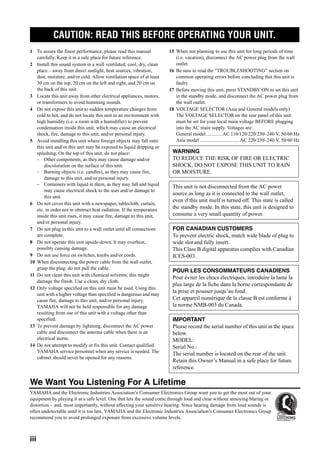
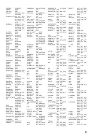
SYSTEM OPTIONS
ADVANCED
OPERATION
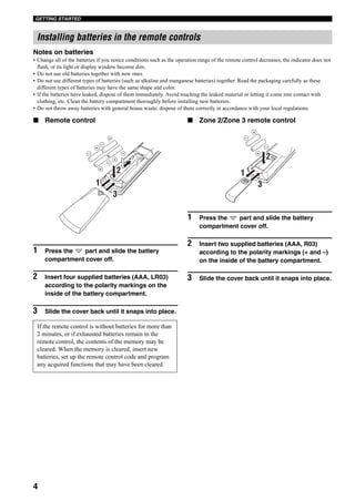
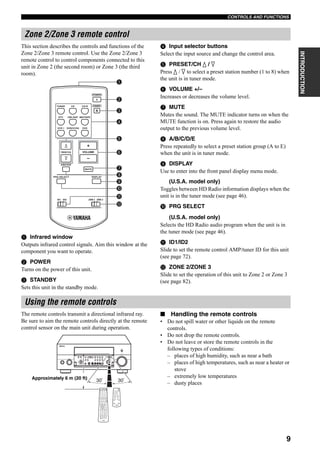
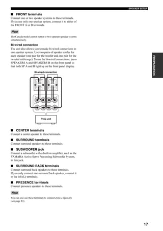
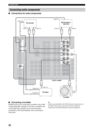
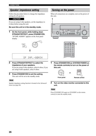
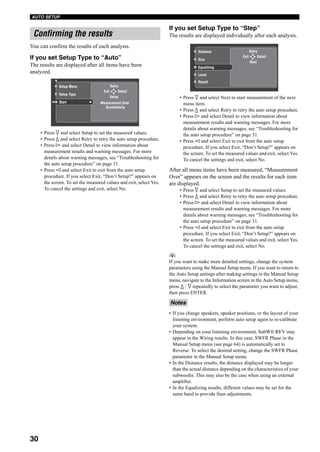
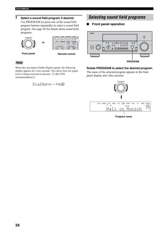
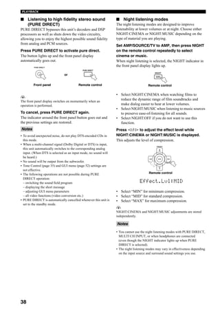
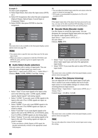
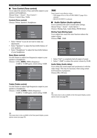
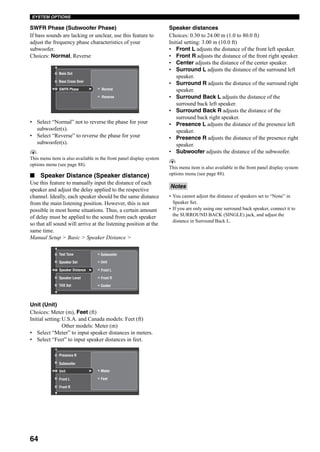
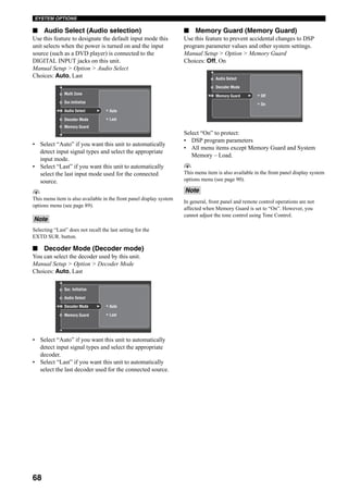
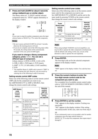
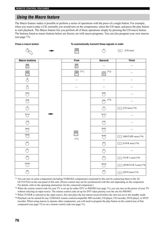
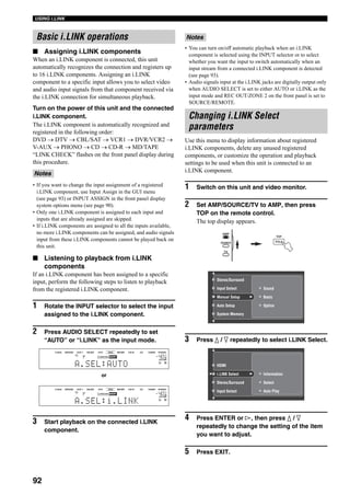
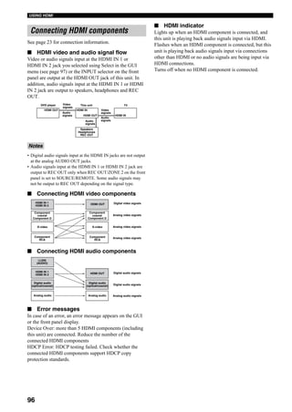
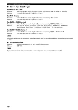
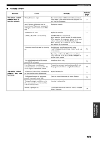
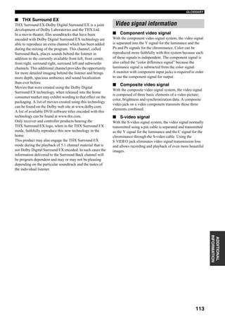
Use this feature to reassign digital input/outputs, select the
input signal, rename the inputs, or adjust the level of the
signal input at each jack.
1 Set AMP/SOURCE/TV to AMP, then press
TOP on the remote control.
2 Select Input Select, then press h.
3 Select the desired input (CD, DVD, etc.), then
press h to access and adjust.
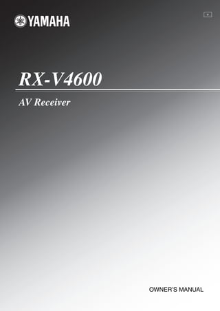
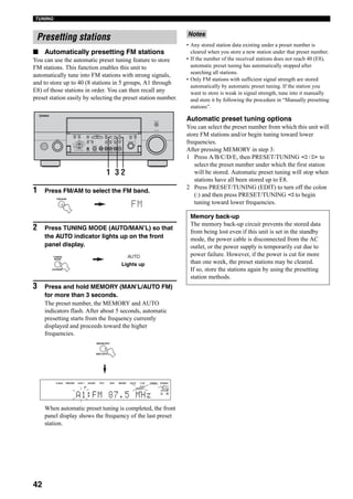
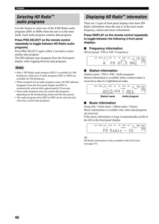
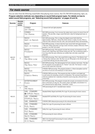
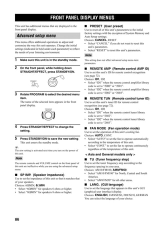
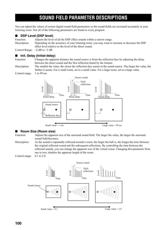
■ Information (Information)
There are 2 types of GUI displays that show HD Radio
information when the unit is in the tuner mode: station and
music information.
Input Select > TUNER > Information >
Station information
(Band / Frequency / Station name / Program /
Program type)
Station information is available when a station name is
received as data in 4 alphabetical codes.
Music information
Page 1: the summary of music information
(Song title / Artist name / Album name)
Page 2: the details of the song title
Page 3: the details of the artist
Page 4: the details of the album
Page 5: the details of the genre
Press l / h repeatedly to toggle between pages.
Press ENTER on the remote control to hold the display
temporarily. “Hold:ENTER” changes to
“Release:ENTER”. Press ENTER again to release it.
Music information is available only when data programs
are received.
y
HD Radio information is also available in the front panel display
menu (see page 46).
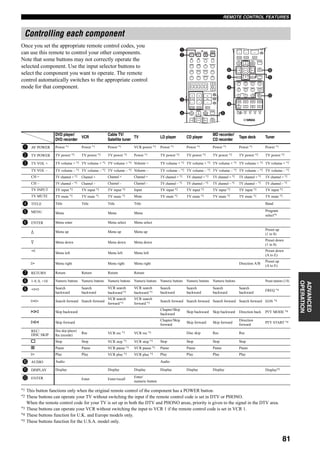
■ I/O Assignment
(Input/output assignment)
You can assign the digital audio input/output and
component video jacks to other components if this unit’s
initial settings do not correspond to your needs. Change
the following parameters to reassign the jacks and
effectively connect more components.
Once the jacks are reassigned, you can select the
corresponding component using the INPUT selector on
the front panel or the input selector buttons on the remote
control.
Input Select > input source (DVD, etc.) >
I/O Assignment >
Example 1:
To assign the COAXIAL 7 (CD) jack to the DVD input.
1) Select Input Select, then select DVD.
2) Select I/O Assignment > Coaxial Input, then select
7 CD.
Input Select
TOP
TITLE
AMP
SOURCE
TV
MD/TAPE
CD-R
DTV
CBL/SAT
DVDInput Select
Manual Setup
Auto Setup
Stereo/Surround
Station
Current
Information
Volume Trim
Rename
Music
Freq.
Program Type
Name
Band
Program
FM
87.50MHz
Current
Station
Music
Hold:ENTER [1] 2
Station
Music](https://image.slidesharecdn.com/c43c0abd-30f7-4179-be0c-5c23df2d1ad9-150717232153-lva1-app6891/85/RX-V4600_e-59-320.jpg)

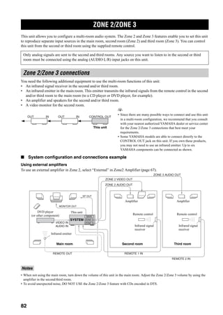

![87
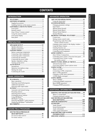
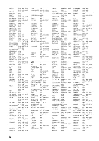
FRONT PANEL DISPLAY MENUS
ADVANCED
OPERATION
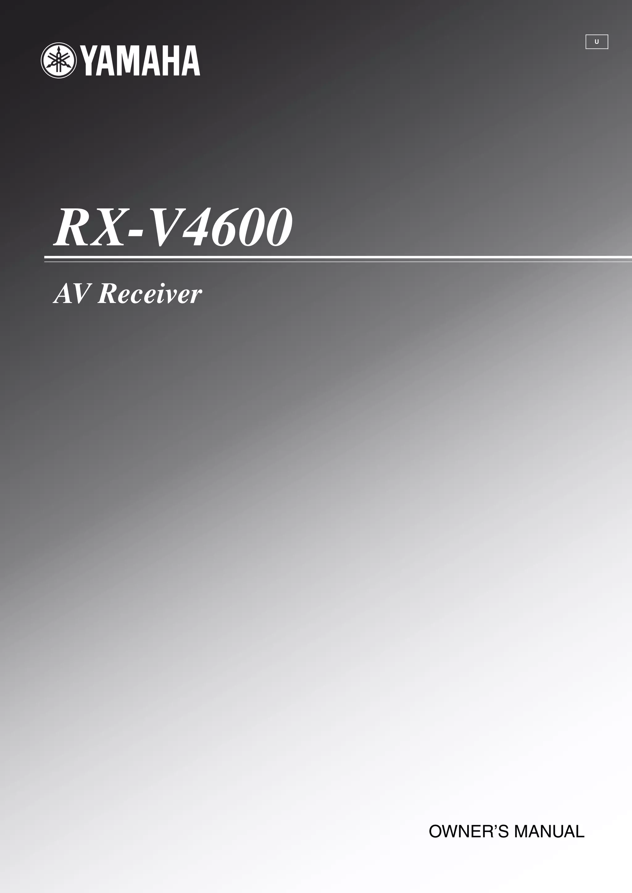
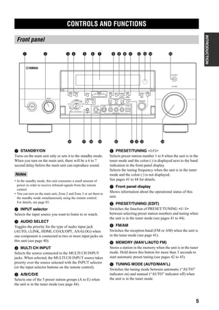
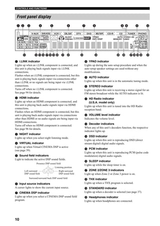
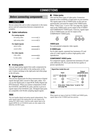
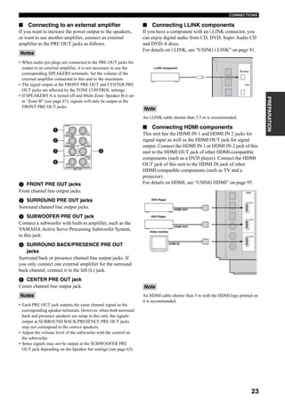
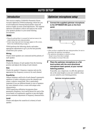
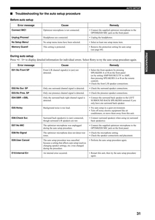
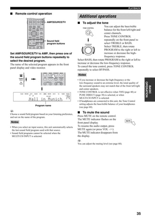
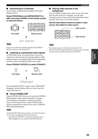
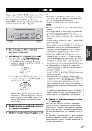
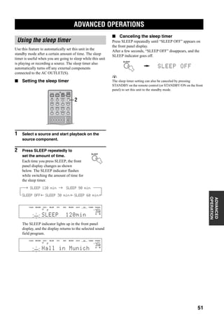
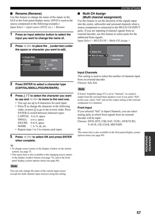
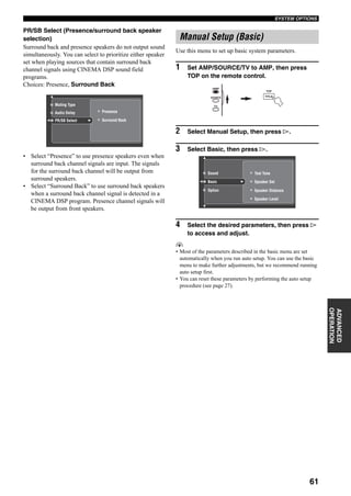
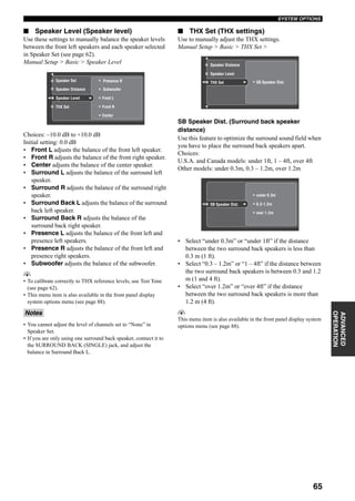
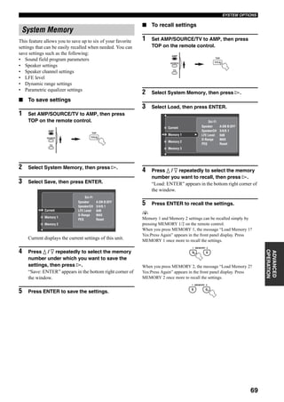
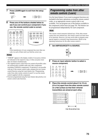
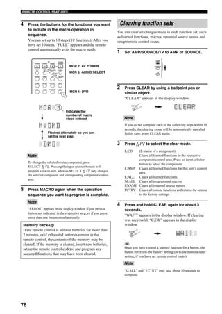
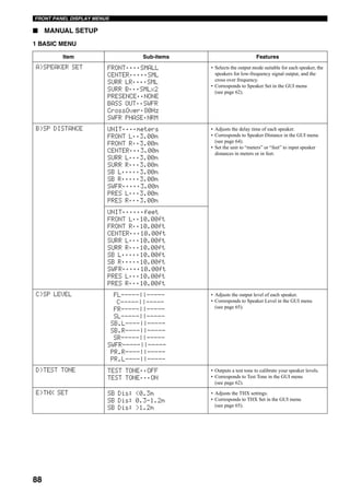
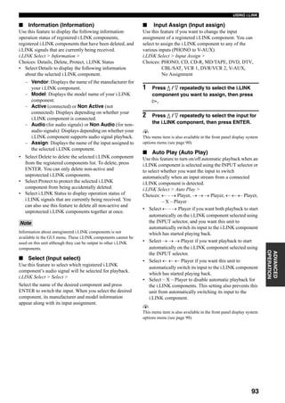
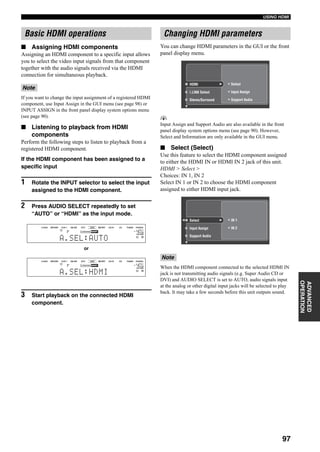
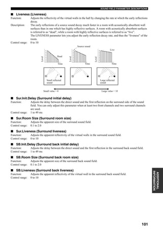
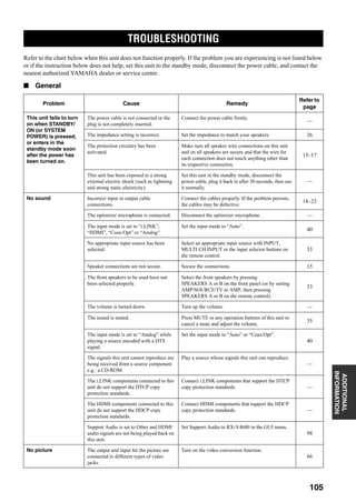
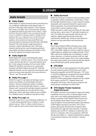
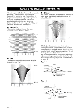
This is a complimentary menu that allows you to access
most GUI menu system option parameters without using a
video monitor.
Use the remote control to access and adjust each
parameter.
1 Set AMP/SOURCE/TV to AMP.
2 Press DISPLAY on the remote control to
enter the menu.
3 Press k / n repeatedly to select an item, then
press ENTER to enter the selected item.
4 Press k / n repeatedly to select the
parameter you want to adjust.
5 Press ENTER, then press l / h repeatedly to
change the setting of the item you want to
adjust.
6 Press DISPLAY to exit.
y
If you want to adjust another parameter, press RETURN to return
to the previously selected menu item.
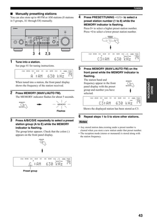
■ AUTO SETUP
Front panel display system options menu
EXIT
MENU
EFFECT
RETURN DISPLAY
STRAIGHT
BAND PRG SELECT
A/B/C/D/E
NIGHT
AUDIO
PURE DIRECT
ENTER
TOP
TITLE
VOL
+
–
CH
+
–
TV VOL
TV MUTE TV INPUT MUTE
+
–
AMP
SOURCE
TV
PRESET
2,6
1
3-5
Item Sub-items Features
SETUP AUTO • Use to specify the speaker parameters auto setup
adjusts.
• Corresponds to Setup Type in the GUI menu
(see page 29).
EQ NATURAL
FRONT
FLAT
• Use to specify the equalizer characteristics auto setup
uses.
• Corresponds to Setup Menu – Equalizing in the GUI
menu (see page 28).
START [ENTER] • Use to activate the auto setup procedure.
• Corresponds to Start in the GUI menu (see page 29).](https://image.slidesharecdn.com/c43c0abd-30f7-4179-be0c-5c23df2d1ad9-150717232153-lva1-app6891/85/RX-V4600_e-91-320.jpg)
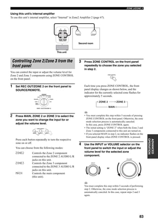
![89
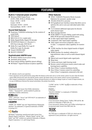
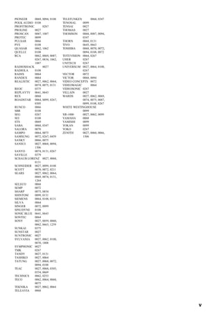
FRONT PANEL DISPLAY MENUS
ADVANCED
OPERATION
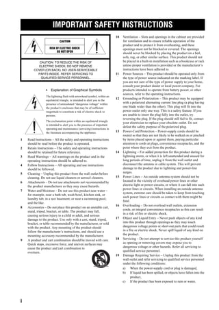
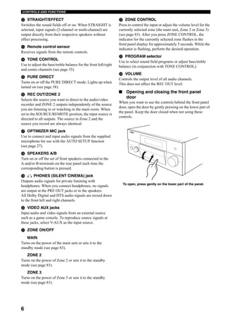
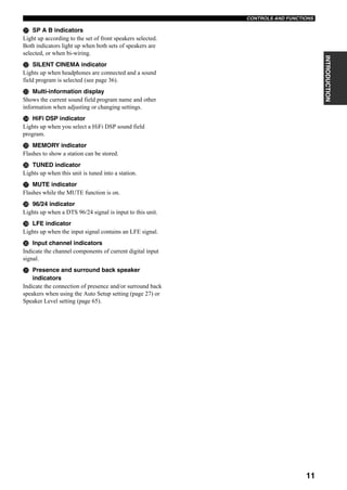
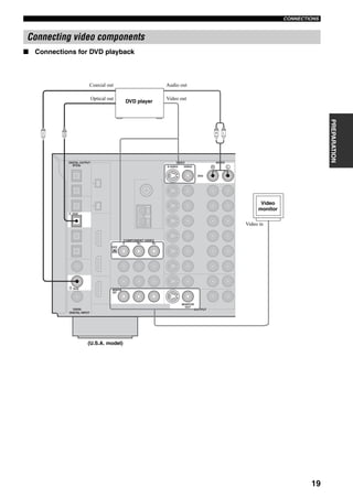
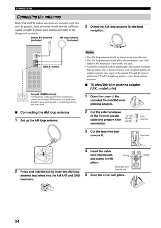
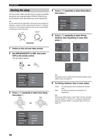
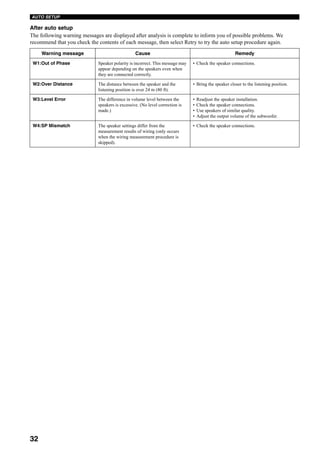
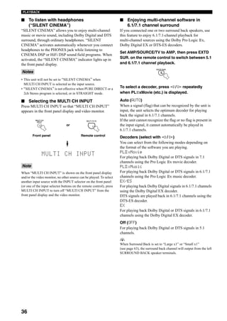
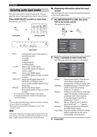
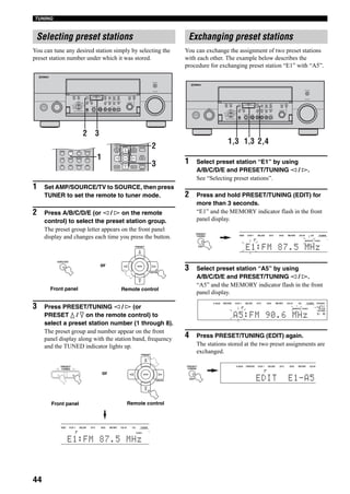
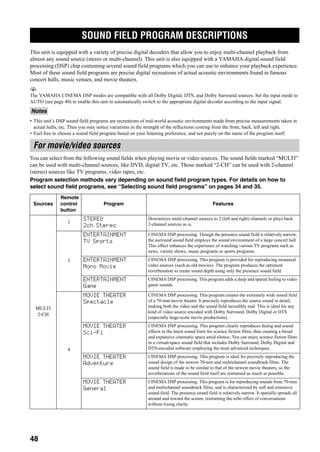
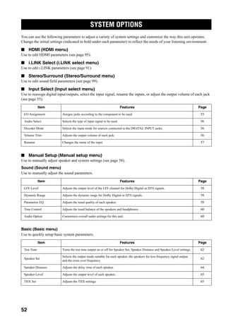
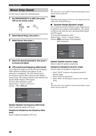
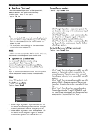
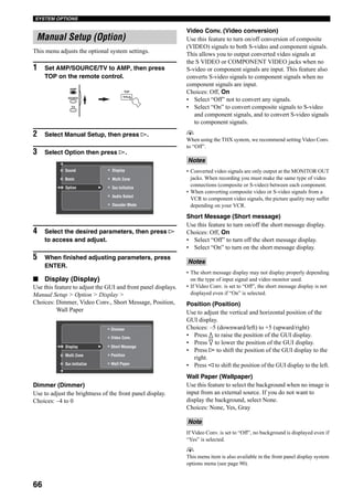
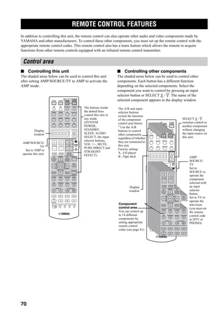
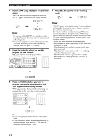
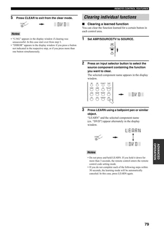
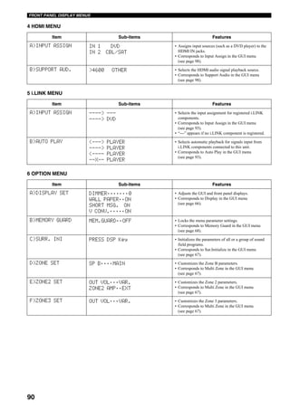
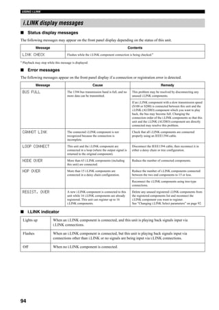
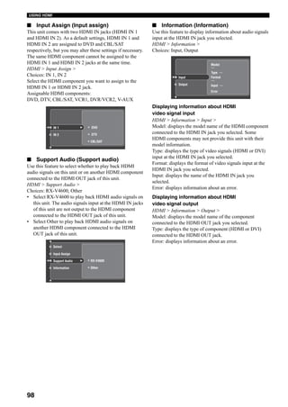
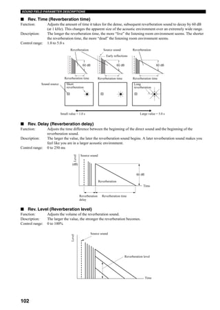
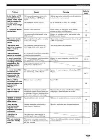
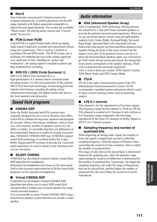
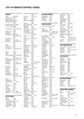
2 SOUND MENU
3 INPUT MENU
Item Sub-items Features
A)LFE LEVEL SP LFE;;;;;;;0
HP LFE;;;;;;;0
• Adjusts the output level of the LFE channel for Dolby
Digital or DTS signals.
• Corresponds to LFE Level in the GUI menu
(see page 58).
B)D.RANGE SP D.R;;;;MAX
HP D.R;;;;MAX
• Adjusts the dynamic range for Dolby Digital or DTS
signals.
• Corresponds to Dynamic Range in the GUI menu
(see page 58).
C)TONE CON FRQ BASS SP 350Hz
TRBL SP 3.5kHz
• Adjusts the tonal balance of the speakers and
headphones.
• Corresponds to Tone Control in the GUI menu
(see page 60).
• “BASS SP” and “TRBL SP” appear when no
headphones are connected to this unit, and
“BASS HP” and “TRBL HP” appear when
headphones are connected to this unit.
BASS HP 350Hz
TRBL HP 3.5kHz
D)AUDIO OPTION A.MUTE;;;;MUTE
A.DELAY;;;;0ms
PRch >SBch
• Customizes overall audio settings for this unit.
• Corresponds to Audio Option in the GUI menu
(see page 60).
Item Sub-items Features
A)I/O ASSIGN C.V[A] DVD
C.V[B] DTV
C.V[C]CBL/SAT
OUT(1)MD/TAPE
OUT(2) CD-R
IN (3) CD
IN (4) DVD
IN (5) DTV
IN (6) CBL/SAT
IN (7) CD
IN (8) DVD
IN (9)DVR/VCR2
• Assigns jacks according to the component to be used.
• Corresponds to I/O assignment in the GUI menu
(see page 55).
B)INPUT TRIM DVD;;;;;0.0 • Adjusts the output volume of each jack.
• Corresponds to Volume Trim in the GUI menu
(see page 56).
C)AUDIO SELECT >AUTO LAST • Selects the initial input mode of the source.
• Corresponds to Audio Select in the GUI menu
(see page 68).
D)DECODER MODE >AUTO LAST • Selects the decoder used by this unit.
• Corresponds to Decoder Mode in the GUI menu
(see page 56).
E)INPUT RENAME DVD ._ DVD • Changes the name of the input.
• Corresponds to Rename in the GUI menu
(see page 57).
F)MULTI CH IN >6CH 8CH • Selects the number of audio channels input at the
MULTI CH INPUT jacks.
• Corresponds to Multi CH Assign in the GUI menu
(see page 57).](https://image.slidesharecdn.com/c43c0abd-30f7-4179-be0c-5c23df2d1ad9-150717232153-lva1-app6891/85/RX-V4600_e-93-320.jpg)
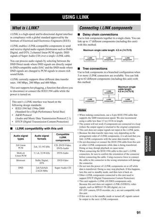

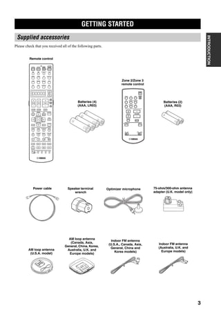
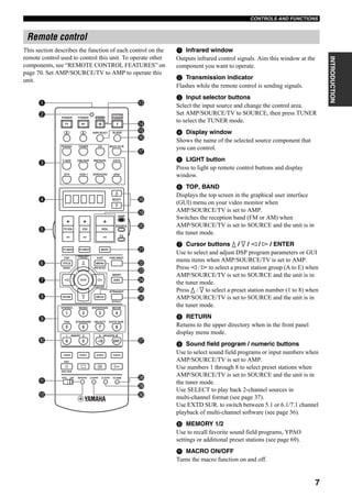
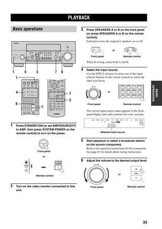
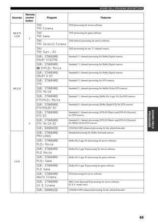
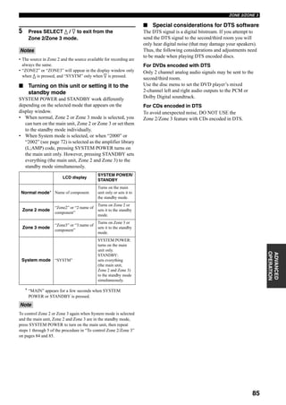
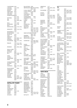
![SPECIFICATIONS
115
ADDITIONAL
INFORMATION
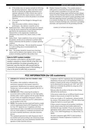
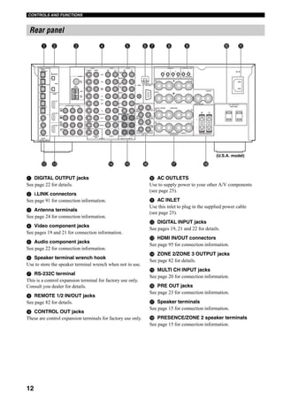
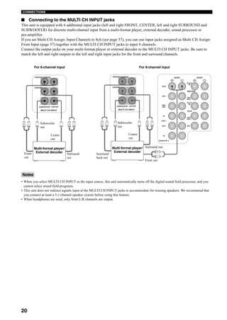
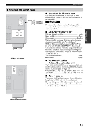
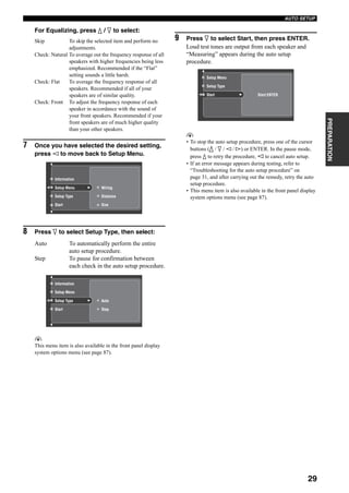
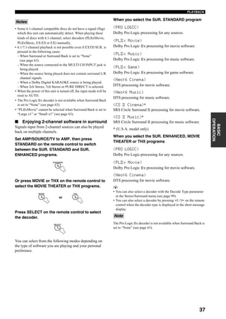
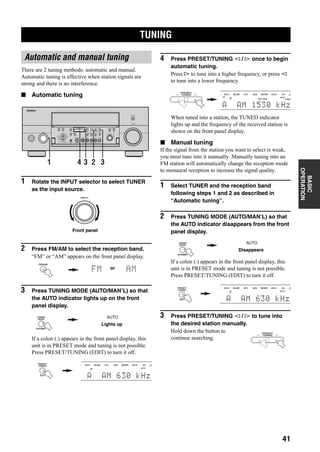
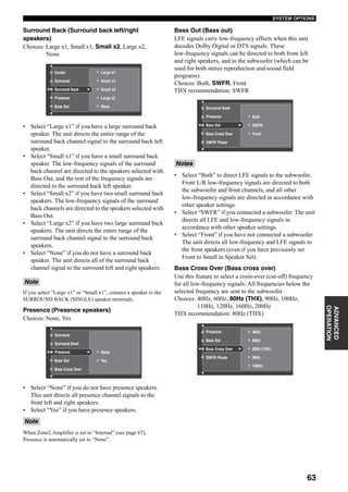
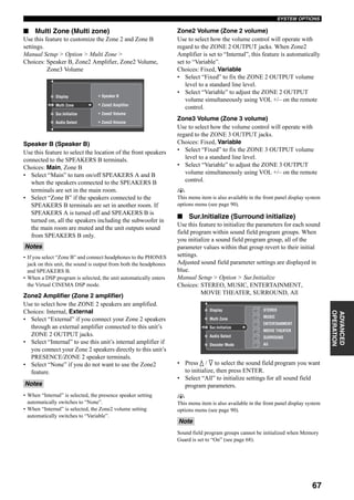
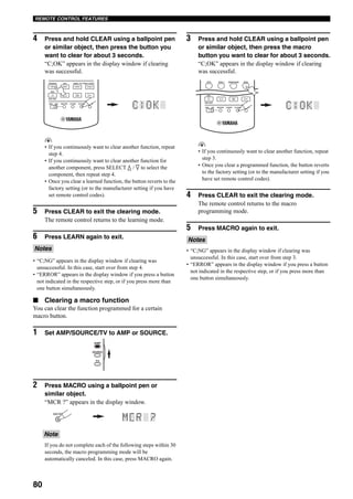
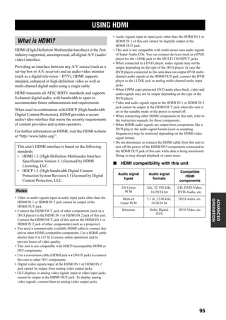
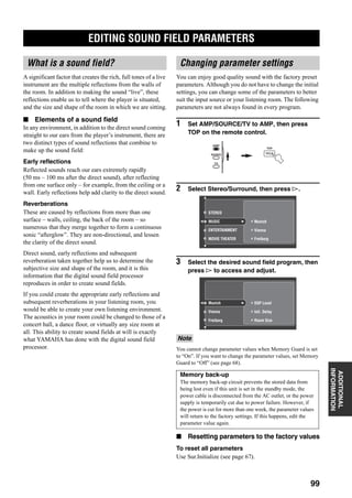
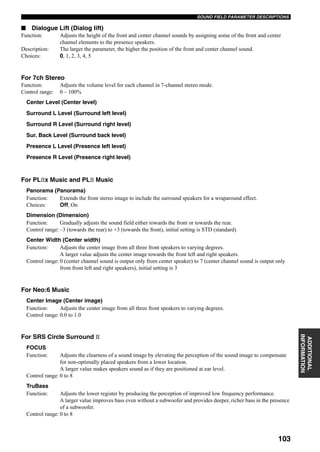
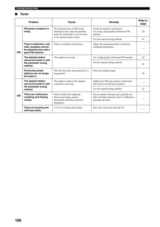
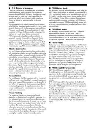
AUDIO SECTION
• Minimum RMS Output Power for Front, Center, Surround,
Surround back
20 Hz to 20 kHz, 0.04% THD, 8 Ω ..................................... 130 W
• Maximum Power (EIAJ)
[Asia, General, China and Korea models]
1 kHz, 10% THD, 8 Ω..........................................................180 W
• Dynamic Power (IHF)
[U.S.A., Canada, Asia, General, China, Korea and Australia
models]
8/6/4/2 Ω ........................................................ 165/205/260/340 W
• DIN Standard Output Power [U.K. and Europe models]
1 kHz, 0.7% THD, 4 Ω.........................................................190 W
• Dynamic Headroom
[U.S.A., Canada, Asia, General, China, Korea and Australia
models]
8 Ω ......................................................................................1.03 dB
• IEC Output Power [U.K. and Europe models]
1 kHz, 0.04% THD, 8 Ω.......................................................140 W
• Damping Factor (IHF)
20 Hz to 20 kHz, 8 Ω...................................................140 or more
• Input Sensitivity/Input Impedance
PHONO .................................................................. 3.5 mV/47 kΩ
CD, etc. ................................................................. 200 mV/47 kΩ
MULTI CH INPUT ............................................... 200 mV/47 kΩ
• Maximum Input Signal
PHONO (1 kHz, 0.1% THD) .............................. 100 mV or more
CD, etc. (1 kHz, 0.5% THD) .................................. 2.4 V or more
• Output Level/Output Impedance
REC OUT ............................................................ 200 mV/1.2 kΩ
PRE OUT ................................................................... 1.0 V/500 Ω
SUBWOOFER ........................................................... 2.0 V/500 Ω
ZONE 2/ZONE 3 OUT ............................................. 1.0 V/1.2 kΩ
[U.S.A., Canada, Australia, U.K. and Europe models]
• Headphone Jack Rated Output/Impedance
CD, etc. (1 kHz, 40 mV, 8 Ω) ............................... 150 mV/100 Ω
• Frequency Response
CD to Front L/R ............................... 10 Hz to 100 kHz, +0/–3 dB
• RIAA Equalization Deviation
PHONO (20 Hz to 20 kHz) .......................................... 0 ± 0.5 dB
• Total Harmonic Distortion
PHONO to REC OUT
(20 Hz to 20 kHz, 1 V) ......................................... 0.02% or less
CD, etc. to Front L/R
(20 Hz to 20 kHz, 65 W, 8 Ω) ............................... 0.04% or less
• Signal to Noise Ratio (IHF-A Network)
PHONO (5 mV) to Front L/R
[U.S.A., Canada, Asia, General, China and Korea models]
.............................................................................. 86 dB or more
[Australia, U.K. and Europe models] ...................... 81 dB or more
CD, etc. (250 mV) to Front L/R ..........................................100 dB
• Residual Noise (IHF-A Network)
Front L/R ................................................................ 150 µV or less
• Channel Separation (1 kHz/10 kHz)
PHONO (shortened) to Front L/R ............... 60 dB/55 dB or more
CD (5.1 kΩ shortened) to Front L/R ........... 60 dB/45 dB or more
• Tone Control Characteristics (Front L/R)
BASS Boost/Cut ....................................................... ±6 dB/50 Hz
BASS Turnover Frequency..................................................350 Hz
TREBLE Boost/Cut ................................................ ±6 dB/20 kHz
TREBLE Turnover Frequency............................................3.5 kHz
• Filter Characteristics (fc=40/60/80/90/100/110/120/160/200 Hz)
H.P.F. (Front, Center, Surround, Surround back) ...........12 dB/oct.
L.P.F. (Subwoofer) .........................................................24 dB/oct.
VIDEO SECTION
• Video Signal Type (Wall Paper)
[Asia, China, Australia, U.K. and Europe models] ................ PAL
[U.S.A., Canada, General and Korea models] .................... NTSC
• Video Signal Type (Video Conversion)
[Asia, General, China, Australia, U.K. and Europe models]
.............................................................................................. PAL
[Other models] .................................................................... NTSC
• Signal Level
Composite ................................................................. 1 Vp-p/75 Ω
S-video ............................ 1 Vp-p/75 Ω (Y), 0.286 Vp-p/75 Ω (C)
Component ................... 1 Vp-p/75 Ω (Y), 0.7 Vp-p/75 Ω (Pb/Pr)
• Maximum Input Level .......................................... 1.5 Vp-p or more
• Signal to Noise Ratio ................................................ 60 dB or more
• Frequency Response (MONITOR OUT)
Composite, S-video .................................. 5 Hz to 10 MHz, –3 dB
Component ............................................... 5 Hz to 60 MHz, –3 dB
FM SECTION
• Tuning Range
[U.S.A. and Canada models] ........................... 87.5 to 107.9 MHz
[Asia and General models] ........ 87.5/87.50 to 108.0/108.00 MHz
[Other models] ............................................ 87.50 to 108.00 MHz
• Usable Sensitivity (IHF) ....................................... 1.0 µV (11.2 dBf)
• Selectivity ................................................................................ 70 dB
• Signal to Noise Ratio (IHF)
Mono/Stereo .............................................................. 76 dB/70 dB
HD [U.S.A. model only] ...................................................... 80 dB
• Harmonic Distortion (1 kHz)
Mono/Stereo ................................................................ 0.2%/0.3%
HD [U.S.A. model only] ..................................................... 0.03%
• Stereo Separation (1 kHz)
Stereo .....................................................................................42 dB
HD [U.S.A. model only] ...................................................... 70 dB
• Frequency Response
Stereo .............................................. 20 Hz to 15 kHz, +0.5, –2 dB
HD [U.S.A. model only] ................ 20 Hz to 18 kHz, +0.5, –3 dB
• Antenna Input (unbalanced) ..................................................... 75 Ω
SPECIFICATIONS](https://image.slidesharecdn.com/c43c0abd-30f7-4179-be0c-5c23df2d1ad9-150717232153-lva1-app6891/85/RX-V4600_e-119-320.jpg)
![116
SPECIFICATIONS
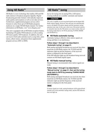
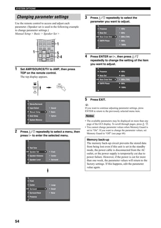
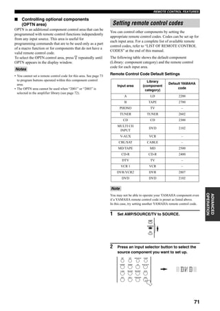
AM SECTION
• Tuning Range
[U.S.A. and Canada models] .............................. 530 to 1710 kHz
[Asia and General models] ................. 530/531 to 1710/1611 kHz
[Other models] .................................................... 531 to 1611 kHz
• Usable Sensitivity ............................................................. 300 µV/m
• Signal to Noise Ratio (IHF)
HD [U.S.A. model only] ...................................................... 80 dB
• Harmonic Distortion (1 kHz)
HD [U.S.A. model only] ..................................................... 0.03%
• Stereo Separation (1 kHz)
HD [U.S.A. model only] ...................................................... 70 dB
• Frequency Response (20 Hz to 12.5 kHz)
HD [U.S.A. model only] ............................................. +0.5/–3 dB
GENERAL
• Power Supply
[U.S.A. and Canada models] .............................. AC 120 V, 60 Hz
[General model] .............. AC 110/120/220/230–240 V, 50/60 Hz
[Asia model].................................... AC 220/230–240 V, 50/60 Hz
[China model] .................................................... AC 220 V, 50 Hz
[Korea model] .................................................... AC 220 V, 60 Hz
[Australia model] ............................................... AC 240 V, 50 Hz
[U.K. and Europe models] ................................. AC 230 V, 50 Hz
• Power Consumption
[U.S.A. and Canada models] ................................. 500 W/630 VA
[Other models] ................................................................... 500 W
• Standby Power Consumption
[U.S.A. and Canada models] .................................... 0.2 W or less
[General model] (AC 240 V, 50 Hz) ...................... 0.33 W or less
[Other models] ....................................................... 0.15 W or less
• Maximum Power Consumption [General model only]
6ch, 10% THD .................................................................. 1100 W
• AC Outlets
[U.S.A. and Canada models]..... 2 (Total 100 W/0.8 A maximum)
[Australia and U.K. models] .............. 1 (Total 100 W maximum)
[Asia and General models] ................... 2 (Total 50 W maximum)
[China and Europe models] ................ 2 (Total 100 W maximum)
• Dimensions (W x H x D) .............................. 435 x 171 x 438.5 mm
(17-1/8” x 6-3/4” x 17-1/4”)
• Weight .................................................................. 18.0 kg (39.7 lbs)](https://image.slidesharecdn.com/c43c0abd-30f7-4179-be0c-5c23df2d1ad9-150717232153-lva1-app6891/85/RX-V4600_e-120-320.jpg)


This document provides contact information for various Yamaha electronics corporations around the world, followed by an owner's manual for the Yamaha RX-V4600 AV receiver. The contact information lists the addresses of Yamaha electronics companies in the USA, Canada, Germany, France, UK, Sweden, and Australia. The owner's manual then provides important safety instructions and explanations of features for the RX-V4600 receiver, covering proper use, installation, specifications, controls, and operation. It includes diagrams of the front panel and remote controls.


