SlideShare a Scribd company logo
1 of 15
Download to read offline
Hiroyuki Sato
International Journal of Intelligent Systems and Applications in Robotics (IJRA),Volume(10) : Issue(1) : 2021
ISSN: 2180-1312, https://www.cscjournals.org/journals/IJRA/description.php 1
Autonomous Driving Control of Automatic Guided Vehicle using
Tablet PC
Hiroyuki Sato sato_h@iwate-pu.ac.jp
Faculty of Software and Information Science
Iwate Prefectural University
Takizawa, 020-0693, Japan
Abstract
In recent years, mobile terminals are inexpensive, but have high performance in both calculation
and display, are equipped with many input / output devices, and are easy to develop software.
Therefore, we thought that it could be used for control devices in the embedded field, and tried to
apply it to control of autonomous guided vehicles (AGVs). The control method is as follows; after
taking a picture of the front passage with a camera and detecting the edge, the points at the
boundary between the passage surface and other objects (walls and shelves) are extracted, and
the left and right approximate straight lines are calculated from the points. Then, it runs with the
intersection of the lines as the center of the passage. The problems were the influence of floor
noise and the detection of incorrect road boundary lines. Therefore, we were able to reduce the
detection of erroneous wall-floor boundary points by applying a noise removal method that makes
the best use of the characteristics of the image, and to improve the detection accuracy of road
boundary lines. With this improvement, the AGV, which initially traveled only about 10m, can be
run to the last 100m of the test course, and as a result of measurement, the average error in the
running direction is reduced to 20%, the maximum error is reduced to 21%, and the variation of
running direction is reduced to 1.4%. The processing time is also about 250 milliseconds, which is
a time that does not hinder the running control every second. From the above results, it is
confirmed that the mobile terminal can be used stably on a relatively wide road, and it is shown
that the mobile terminal can be applied to the embedded system.
Keywords: Mobile Computing, Embedded System, Autonomous Driving, Image Processing.
1. INTRODUCTION
In recent years, the spread of smartphones and tablet PCs has slowed down in developed
countries, but it is still increasing. With this widespread use, technical improvements such as
improved performance of the built-in processor have increased dramatically. The processors
installed in the latest mobile terminals have the same or better performance than the processors
used in the conventional embedded field (Singh et al., 2014). Recently, they have been used as
game terminals, and not only CPU performance but also GPU performance has improved. Mobile
terminals are also equipped with a wealth of input devices such as cameras, GPS, acceleration
and geomagnetic sensors. And Android, which is a representative OS for mobile terminals, has
abundant libraries for handling various sensors and creating an easy-to-use user interface, and in
software development, functions such as input / output can be easily developed. Therefore, we
can focus on algorithm development. In addition, the popularity of mobile terminals has made it
possible to use them at very low prices due to market forces.
In this way, mobile terminals are inexpensive, but have high performance in both calculation and
display, are equipped with many input / output devices, and are easy to develop software.
Therefore, we thought that this mobile terminal could be used as a control device in the
embedded field, and tried to apply it to the autonomous driving control of autonomous guided
vehicles (AGVs) in manufacturing factories.
Hiroyuki Sato
International Journal of Intelligent Systems and Applications in Robotics (IJRA),Volume(10) : Issue(1) : 2021
ISSN: 2180-1312, https://www.cscjournals.org/journals/IJRA/description.php 2
In embedded systems that control such machines, the Jetson series equipped with NVIDIA GPUs
has become popular in recent years. Although it has extremely high computing power, the status
display is poor with the processor board alone, and it is difficult to use it for workers in
manufacturing factories who are unfamiliar with computers. On the other hand, tablet PCs are not
so high in performance compared to ultra-high-speed processor boards such as the Jetson series
because they apply interpreter method. However, it is easy to use even for users who are
unfamiliar with computers, since the display equipped with a touch panel is integrated. Therefore,
the tablet PC will become an easy-to-use processor in the embedded field, if the amount of
processing is kept low.
In the manufacturing plant we are applying to, a magnetic tape that serves as a running guide is
attached to the floor, and the AGV runs along the tape. There is a problem that the guide needs
to be reattached every time the travel route is changed, a lot of time and labor are spent during
this laying work, and the system must be stopped during the laying work. Therefore, autonomous
driving of AGVs that do not require such a guide is desired.
In order to reduce the processing amount of AGV autonomous driving so that it can be processed
even on a tablet PC, this time we will only apply and evaluate driving on a relatively wide straight
road. When turning at intersections, we will either use signs (Haginiwa et al., 2015) or use
conventional magnetic tape. In the manufacturing plant to which it is applied, traveling on a
relatively wide straight road accounts for a large proportion of the total distance, so if the straight
road can be driven autonomously, it greatly contributes to labor saving in the work of laying
magnetic tape.
The purpose of our study is to verify that we built an algorithm that can control the running of AGV
with only the information input from one camera, and does it operate with sufficient performance
and accuracy on the processor installed in the mobile terminal (tablet PC). The goal is to run on a
straight road with a width of 5 m and a length of about 100 m, which is the main passage in the
target manufacturing plant, at 1 m per second which is the maximum speed of AGV stipulated by
the domestic regulations. If this method fails to run, we will consider using various sensors other
than the camera, such as GPS, and acceleration and geomagnetic sensors.
In this paper, Chapter 2 first describes the research trends of general automatic guided vehicles
and autonomous driving control, and then Chapter 3 describes the outline of this system, the
outline of the traveling control method adopted this time, and its problems. Then, after showing
the solution to the problem in Chapter 4, we evaluate it in Chapter 5. Finally, Chapter 6 concludes
our research.
2. TRENDS IN AUTOMATED GUIDED VEHICLES AND AUTONOMOUS
DRIVING CONTROL TECHNOLOGY
The traveling control methods for automated guided vehicles (AGVs) that carry parts at
manufacturing plants can be broadly classified into two types. One is a guide-type control
(Kamewaka et al., 1987) (Tsumura, 1986) that is controlled by using a guide such as a magnetic
tape, and the other is a guideless control (Vis, 2006) (Martinez-Barbera et al., 2010) that does not
require a guide.
2.1 Guide-type Control
Guided-type control occupies about 80% of the AGV market, because it is possible to control
driving with extremely high accuracy by traveling along the guide. However, the problem in
performing this guided-type control is the large amount of labor and time required for laying. It is
necessary to lay a guide to introduce the AGV for the first time, and every time the travel route is
changed due to a layout change etc., the guide is peeled off and re-laying is repeated. There are
problems that a lot of time and labor is spent during this laying work, and the system must be
stopped during the laying work.
Hiroyuki Sato
International Journal of Intelligent Systems and Applications in Robotics (IJRA),Volume(10) : Issue(1) : 2021
ISSN: 2180-1312, https://www.cscjournals.org/journals/IJRA/description.php 3
2.2 Guideless Control
Guideless control is being researched to solve the trouble of laying guides, which was a problem
in guide-type control. This is a method of running control using a laser beam (Smieszek et al.,
2015), a gyro sensor (Shi et al., 2004), and an image sensor (Sabikan et al., 2010) (Lee et al.,
2013) (Yu et al., 2009) instead of laying a guide. However, it has not become very popular,
because the sensor becomes expensive, and a high-performance processor is required to
calculate the self-position with the same accuracy as the guide type.
In this way, the guide type control has the advantage of being able to control with high accuracy,
but has the disadvantage of requiring labor and time for the guide facility. On the other hand,
guideless control has the advantage of not requiring a guide facility, but has the disadvantage of
being expensive.
2.3 Research Trends In Autonomous Driving Control
In recent years, research and development of autonomous driving control of commercial vehicles
has been remarkable, and the situation is that the commercialization of conditional driving
automation of automatic driving level 3 is just around the corner. In these automatic driving, many
sensors such as monocular / stereo camera, ultrasonic sensor, radar, rider, GPS are installed in
the cognitive part, and control judgment is made by making full use of communication via 3D map
and the Internet. Similar to the guideless control described above, this control judgment method is
expensive as an autonomous driving control method for AGVs, and it is difficult to apply the same
method to AGVs.
Therefore, in this research, guideless control, which is not be widespread due to the use of many
expensive equipment, is realized at a low price by using an inexpensive tablet PC. In this
research, the front is photographed by the camera mounted on the tablet PC, and the driving
control is judged by image processing. Autonomous driving control by similar image processing
has been studied a lot for a long time.
In (Kawabe et al., 2002), the front is imaged with two CCD cameras, and the passage line is
detected by edge detection, thinning, isolated point removal, masking, and Hough transform. In
(Hashiba et al., 2002), running control is performed using a teacher image, and in (Tanabe et al.,
2008), the speed of passage line detection by Hough transform is increased. Then, in (Nagae et
al., 2008), by changing the threshold value and binarizing the captured image, a plurality of
information such as the fluorescent lamp light source, the road boundary, and the vanishing point
are integrated to perform highly reliable driving control.
In these studies, there is no focus on reducing the price of the device, and although there are
some low-priced small devices that use notebook PCs, there are no cases that use mobile
terminals such as tablet PCs. However, many of them adopt a relatively simple traditional
method, and it can be said that it is close to the algorithm that suppresses the amount of
calculation in our research, which will be described later.
On the other hand, looking at the recent trends over the last five years, there are three major
trends. The first is to improve self-positioning accuracy by combining multiple sensors (Zhou et al.,
2018) (Zhou et al., 2020) (Wang et al., 2020). Examples of the sensors include a gray scale
sensor, an ultrasonic wave, an infrared sensor, an optical camera, and a rider.
Next, there are many systems that employ learning (Sierra-García et al., 2020) (Sant et al., 2020)
(Chuixin et al., 2019). It seems that these are largely due to the recent AI boom, but there are
some that use reinforcement learning, which improves accuracy by repeating learning, and deep
learning, which has attracted the most attention in the AI boom.
As a final tendency, many systems have applied SLAM (Simultaneous Localization and Mapping)
(Durrant-whyte, 2006), which has been attracting attention as a self-positioning method in recent
years (Chen et al., 2017) (Chen et al., 2020) (Li et al., 2018). SLAM is a technology that
Hiroyuki Sato
International Journal of Intelligent Systems and Applications in Robotics (IJRA),Volume(10) : Issue(1) : 2021
ISSN: 2180-1312, https://www.cscjournals.org/journals/IJRA/description.php 4
simultaneously identifies the self-position and creates an environmental map, and by proceeding
while learning even in an unknown environment, the machine grasps where you are relatively and
what is happening around you. Compared to GPS, which also identifies self-position, the SLAM
can be applied indoors where radio waves do not reach or in situations where the surrounding
conditions change in detail, enabling highly accurate self-position identification in various
situations.
In these recent AGVs, multiple sensors are used, learning, and SLAM are used in order to
improve the self-positioning accuracy, but all of them require a very large amount of calculation. It
can be processed by using a recent small high-performance processor, but the processor on the
mobile terminal using in our research probably cannot handle it. In our research, we have made it
possible to process even an inexpensive mobile terminal by adopting a simple method at the
expense of accuracy to some extent. This point is different from recent technological trends and
is also a unique feature.
3. SYSTEM OVERVIEW
3.1 System Configuration
This system consists of the following.
a) Tablet PC: Equipped with a driving control system. Power is supplied via USB by
transforming the 12V battery for commercial vehicles installed for AGV driving to 5V.
b) RT--ADK: A PIO transfer device for Android that is connected to a tablet PC via USB,
receives instructions such as running, stopping, and turning left and right from the tablet PC,
and sends the corresponding 5V signal to the AGV control panel.
c) AGV control panel: A device that controls the drive unit.
d) Drive unit: A device that runs an AGV according to instructions from the AGV control panel.
e) Operation switch: power switch, emergency stop button.
f) Obstacle sensor: A device that detects obstacles
In addition, FIGURE 1 shows the appearance of this system and the screen of a tablet PC.
FIGURE 1: Appearance of our system and tablet PC screen.
3.2 Flow of Driving Control System
The basic processing flow for AGV drive control will be explained. The image is taken using the
camera mounted on the tablet PC, edge detection is performed to extract the change point from
the image, and the road boundary is detected to narrow down to only the road information, and
the road center (traveling direction) is detected from the intersection of road boundary lines, and
the traveling direction is instructed to the AGV. And again, it is a flow that repeats at 1 second
intervals from camera shooting. When an obstacle is detected by the obstacle sensor originally
Hiroyuki Sato
International Journal of Intelligent Systems and Applications in Robotics (IJRA),Volume(10) : Issue(1) : 2021
ISSN: 2180-1312, https://www.cscjournals.org/journals/IJRA/description.php 5
installed on the AGV or when the stop button on the operation panel is pressed, a stop command
is sent to the AGV to stop the vehicle on the spot. When turning at an intersection, etc., place a
sign there and turn by recognizing the sign (Haginiwa et al., 2015).
(a) captured image (b) After edge detection
(c) After boundary detection (d) After road boundary lines detection (e) Boundary lines & captured image
FIGURE 2: Example at university floor.
a) Camera Shooting
First, a camera image is taken to obtain road information. When shooting with a normal tablet PC
camera, image data is captured in the YUV format data type, converted to RGB format, and
displayed as a color image on the display. However, we thought that sufficient road information
could be obtained even with a grayscale image based on a Y signal in YUV format, and we used
the Y signal for speeding up, since this research system is for real-time. FIGURE 2 (a) shows the
images taken on our university campus.
b) Edge Detection
Edge detection is performed to make it easier to obtain road information from grayscale images.
There are various edge detection methods. For some of these methods, we measured the time
from camera shooting (image size 640 x 480) to edge detection, and compared the accuracy and
processing time of edge detection. As a result, we adopted the Sobel filter that compared both the
horizontal and vertical directions. FIGURE 2 (b) shows the image after edge detection in (a).
c) Boundary Extraction
In order to obtain road information, the boundary between the road surface and other objects
such as walls, shelves, and figurines is extracted. In the AGV driveway, there are no objects on
the road surface that would interfere with the AGV, but there are often objects at both edges of
the road. Therefore, there are few edges on the road surface, and the boundary with the wall
surface can be detected as edges. Since the bottom of the captured image is a road, the
boundary can be extracted by extracting the points that first reaches the edge when viewed from
the bottom of the image. FIGURE 2 (c) shows the result of extracting only the boundary between
the road and the wall surface from (b).
d) Calculation of Straight Line at The Road Boundary
In order to simplify the information on the road boundary, a straight line approximated to the
extracted points (edges) at the boundary is calculated for each of the left and right sides. These
Hiroyuki Sato
International Journal of Intelligent Systems and Applications in Robotics (IJRA),Volume(10) : Issue(1) : 2021
ISSN: 2180-1312, https://www.cscjournals.org/journals/IJRA/description.php 6
lines are called road boundary lines. There are various methods for calculating the approximate
straight line, such as the Hough transform and the calculation of the straight line passing over the
most points. In consideration of the processing time, we decided to use the method of calculating
a straight line by the least squares method in this study. FIGURE 2 (d) shows the approximate
straight line from the road boundary of (c). In addition, FIGURE 2 (e) shows a diagram in which
straight lines on the road boundaries are superimposed on the photographed image.
e) Driving Direction Instruction
Travel control is often determined the direction of travel based on the angle of the road boundary
line with the X-axis. However, the road boundary changes due to noise such as reflections and
dirt caused by lighting on the road surface, which often causes a large change in the angle with
the X-axis. The calculated intersection of the left and right road boundary lines is the center of the
road and represents the direction in which the AGV should travel. Therefore, from the relationship
between the intersection of the left and right road boundary lines and the left and right centers of
the image, the AGV gives an instruction to turn right if the former is on the left, turn left if the
former is on the right, and go straight if they overlap. In addition, the turning angle is changed by
changing the length of the instruction signal according to the degree of difference between the
intersection of the road boundary and the center of the image.
3.3 Driving Status and Problems
With the above control method, we verified whether the travel direction instruction was issued in
the correct direction. As a result of the experiment, it was found that the correct driving direction
can be given in the place where the left and right road boundaries can be clearly detected by the
above control method. Then, we tried to verify it in the factory where the AGV actually runs. The
verification environment is as follows.
a) Road length and width: Approximately 100m, Approximately 5m.
b) Road brightness: Uniform brightness with fluorescent lights.
c) Road surface: Concrete (with some light reflection).
In the verification, we started from the center of the road and observed the running of the AGV. In
order to see what would happen if the road boundary changed, we also conducted a running test
from the opposite side of the test course. The location where the running test was conducted is
shown in FIGURE 3.
FIGURE 3: Captured image at the factory.
As a result of the verification, there were many cases where the road boundary could not be
detected accurately, and there was a problem of large meandering, and the average mileage was
only 10 m. Even though the driving direction instructions were correctly issued in the university
environment, it was not possible to drive correctly in the factory environment. Therefore, I held the
tablet PC in my hand and confirmed that the driving direction instructions were correctly issued.
As a result, the correct driving direction instructions were given in the place where the road
boundary can be taken correctly, but the driving direction instructions were not given correctly,
when there is noise on the driving road surface such as dirt on the road surface, color
Hiroyuki Sato
International Journal of Intelligent Systems and Applications in Robotics (IJRA),Volume(10) : Issue(1) : 2021
ISSN: 2180-1312, https://www.cscjournals.org/journals/IJRA/description.php 7
unevenness, and magnetic tape of the current AGV. That is, the following two are the main
causes of meandering.
a) Effect of floor noise
b) Incorrect detection of road boundary lines
(a) After edge detection (b) After road boundary line detection (c) Boundary lines & captured image
FIGURE 4: Example at factory floor.
(a) After edge detection (b) After road boundary line detection (c) Boundary lines & captured image
FIGURE 5: Example at factory floor where edge detection threshold is changed.
FIGURE 4 (a) is the result of edge detection of FIGURE 3. It can be seen that there is a lot of noise
on the floor. The results of detecting the road boundary based on FIGURE 4 (a) are (b) and (c),
and it can be seen that the road boundary cannot be detected correctly.
FIGURE 5 is the result of raising the edge detection threshold in order to remove floor noise. Floor
noise has been removed, but road boundaries remain incorrect.
4. PROPOSAL OF IMPROVED METHOD
From the results in the previous section, we added "noise removal such as dirt on the road
surface" between b) edge detection and c) boundary extraction, and "removal of incorrect road
boundaries" between c) boundary extraction and d) calculation of straight line at the road
boundary. Each is explained below.
4.1 Noise Removal on the Road Surface
The noises here refer to dirt on the road surface and the magnetic tape of the current AGV. The
purpose of this improvement is to extract the boundary more accurately by removing these
noises.
The boundaries are obtained by extracting the points that first reaches the edge when viewed
from the bottom of the image. However, the boundaries may not be extracted correctly due to the
presence of noise on the road surface. As a noise removal method, it is conceivable to mask the
part of the image taken by the camera corresponding to the road surface and delete all the edges
in it. However, it is necessary to make a mask that suits all road widths and decide which mask to
use each time, since there are various widths of roads. There is also a method of removing noise
Hiroyuki Sato
International Journal of Intelligent Systems and Applications in Robotics (IJRA),Volume(10) : Issue(1) : 2021
ISSN: 2180-1312, https://www.cscjournals.org/journals/IJRA/description.php 8
by changing the threshold value when detecting edges. However, the edge of the magnetic tape
of the current AGV is strong, and there is a problem that the edge of the correct boundary is also
removed when the threshold is raised.
As a feature of the image after edge detection, there are strong linear edges of magnetic tape on
the road surface, but there are few other edges. On the other hand, there are many edges on the
walls and boundaries because there are many objects. Therefore, we decided to divide the image
after edge detection into multiple regions vertically and horizontally, and if the ratio of the number
of edges in each region does not exceed the threshold value, remove all the edges in that region.
Specifically, the screen is divided into 10 parts vertically and horizontally, and if the ratio of edges
in the divided areas is less than 15%, all the edges in that area are removed. An example is
shown in FIGURE 6. The left (a) is the result before noise removal, and the right (2) is the result of
noise removal by this method.
(a) Before improvement (b) After improvement
FIGURE 6: Before and after improving noise removal.
4.2 Removal of Wrong Road Boundaries
Although it was possible to remove noise on the road surface by noise removal, there are some
parts where the boundary between the road and the wall cannot be detected accurately due to
the shadows caused by lighting and the unevenness of the road boundaries. Therefore, we
improved it so that the road boundary lines are generated by the following procedure.
(1) The screen is divided vertically into multiple areas, and straight lines (partial road boundary
lines) that approximate the points at the boundaries are calculated in each area. The specific
number of divisions is 10.
(2) If each partial road boundary line has different characteristics from others, it is judged that
the boundary of that area is wrong and all edges of that area are deleted.
(3) Left and right road boundary lines are generated with remaining edges of the boundary.
The procedure for determining that it is wrong is as follows.
(a) For each division point, count the number of partial road boundary lines in which the vertical
coordinates of the midpoints of the left and right partial road boundary lines are gradually
lowered toward both ends, and let the division point with the largest count value be the
center of the road. This center is different from the center of the road, which is the direction
of travel.
(b) Next, when viewed from that center, it is judged that the partial road boundary lines where
the left partial road boundary lines go down to the right and the right partial road boundary
lines go down to the left is wrong.
(c) Calculate the average height of the intersection of the remaining partial road boundary lines
with the left side of the screen, and judge that the partial road boundary lines that are a
certain amount away (specifically, 96 dots at 1/5 of the screen height) from the average are
wrong.
Hiroyuki Sato
International Journal of Intelligent Systems and Applications in Robotics (IJRA),Volume(10) : Issue(1) : 2021
ISSN: 2180-1312, https://www.cscjournals.org/journals/IJRA/description.php 9
(d) Calculate the average of the slopes of the remaining partial road boundary lines on each of
the left and right sides, and judge that the partial road boundary lines that are a certain
amount away (specifically, less than half or more than double) from the average are wrong.
The boundary edges corresponding to the partial road boundary lines judged to be wrong are
deleted, and the left and right road boundary lines are generated from the remaining boundary
edges. FIGURE 7 shows an example. Since the partial road boundary lines of the left two areas
have different characteristics from the partial road boundary lines of the other areas, the
boundary edges of these areas have been deleted. As a result, the intersection of the left and
right road boundary lines is almost the center of the road.
(a) Removing of partial border (b) Partial border & captured image
FIGURE 7: Removal of incorrect boundary.
5. EXPERIMENTAL RESULTS
When the above improvements were made and the vehicle was run in the same environment as
Section 3.3, it was possible to complete the 100m road, which was a considerable improvement
compared to the average mileage of 10m before the improvement. Therefore, it was confirmed
that the purpose of this study was achieved. The purpose is to build an algorithm that can control
the running of the AGV with only the information input from one camera, and to operate it with
sufficient performance and accuracy on the processor installed in the mobile terminal.
Verification on the test course revealed that the improvement was effective. Therefore, we
quantitatively evaluated how much noise removal and removal of wrong road boundaries were
effective for stable running of AGV. The evaluation was performed as follows. We manually
pushed the AGV equipped with the tablet PC to move it forward on the straight road in the factory
and took the image in front at 1 second intervals. During this taking image, the AGV was
advanced straight toward the destination in order to keep the driving direction constant. In this
experiment, 108 images were taken. Then, for each of these 108 images, the following six types
of travel control methods were used to calculate the travel direction per second, and to obtain the
difference from the ideal travel direction. This difference was the number of pixels on the screen.
(1) A method that removes noise and the wrong road boundaries (improved method).
(2) A method that does not improve anything (method before improvement).
(3) A method that only removes noise.
(4) A method that only removes the wrong road boundaries.
(5) A method that masks the floor surface instead of noise removal.
(6) A method that masks the floor surface instead of noise removal and removes the wrong road
boundaries.
TABLE 1 shows the specifications of the tablet PC used for the measurement, and TABLE 2
shows the measurement results. In addition, FIGURE 8 shows the loci in all traveling directions
(traveling from left to right in the figure) of each method and the running control results at 70
seconds from the start.
Hiroyuki Sato
International Journal of Intelligent Systems and Applications in Robotics (IJRA),Volume(10) : Issue(1) : 2021
ISSN: 2180-1312, https://www.cscjournals.org/journals/IJRA/description.php 10
It can be seen that the difference (error) between the traveling direction calculated by the control
method and the ideal value is small for (1) the improved method. Compared to (2) the methods
before the improvement, the average error is reduced to 20%, the maximum error is reduced to
21%, and the variation in the traveling direction is reduced to 1.4%. From these facts, it can be
seen that our proposal improvement is very effective.
TABLE 1: Specification of tablet PC used for measurement.
TABLE 2: Measurement results.
Next, regarding the effect of each improved method, the effect of removing the wrong road
boundaries is higher, because (4) is better than (3). However, it can be seen that the synergistic
effect of both is high, because the accuracy of (4) is considerably lower compared to the case of
(1) where both improvements are applied.
From the results of (5) and (6), it is found that the effect of removing noise on the floor surface by
mask processing is quite high. The variance is small because the boundary of the mask is located
near the road boundary and there is no major failure in road boundary detection. This experiment
went well because it was carried out on an almost straight road, but if there is a gentle curve,
there is a risk that the road boundary will disappear due to the mask, so it is difficult to use the
mask in practice.
The processing time has increased by about 40 milliseconds from before the improvement, but it
is about 250 milliseconds, which is a time that does not hinder the running control every second.
From the comparison of (2) and (3), it can be seen that the 40 milliseconds of the increment is
mostly due to noise removal. Note that applying a mask to the floor shortens the processing time,
because edge detection is not performed inside the mask.
The maximum value of the difference (error) between the traveling direction and the ideal value
calculated by the proposed method (1) is 68 dots from TABLE 2. It means that there was a
deviation of about 0.5 m from the load width of 5 m, since this is about 10% of the width of the
screen of 640 dots. It was found that it is possible to drive without hitting the wall if the road is
about 1.5 m, since the width of the AGV is about 50 cm. Actually, we couldn't drive well in the
road with a width of about 1.2m.
Product Name ASUS ZenPad 8.0 (Z380M)
OS Android 6.0.1
CPU MediaTek MT8163 Processor 1.3GHz
Main Memory 2GB
Display 8-inch wide TFT color (1,280x800)
Web Camera Front: 500 pixels, Rear: 2 million pixels
Sensor GPS, acceleration, light, magnetism, electronic compass
Communication IEEE802.11a / b / g / n, Bluetooth R 4.0
Driving time about 8 hours
Size 123mm × 209mm × 8.5mm
Weight about 350g
Method Difference from ideal value (pixels) Processing
Time (ms)
Average MAX Variance
(1) 19.60 68 201 252
(2) 99.08 323 14,429 213
(3) 47.77 323 6,596 251
(4) 37.27 291 2,434 213
(5) 22.92 69 181 131
(6) 23.39 71 196 131
Hiroyuki Sato
International Journal of Intelligent Systems and Applications in Robotics (IJRA),Volume(10) : Issue(1) : 2021
ISSN: 2180-1312, https://www.cscjournals.org/journals/IJRA/description.php 11
(1) Improved method (Removing noise & wrong road boundaries)
(2) Before improvement
(3) Removing only noise
Hiroyuki Sato
International Journal of Intelligent Systems and Applications in Robotics (IJRA),Volume(10) : Issue(1) : 2021
ISSN: 2180-1312, https://www.cscjournals.org/journals/IJRA/description.php 12
(4) Removing only wrong road boundaries
(5) Masking floor surface
(6) Masking floor surface & removing wrong road boundaries
FIGURE 8: Whole traveling trajectories and driving control result at 70 seconds of each method
Hiroyuki Sato
International Journal of Intelligent Systems and Applications in Robotics (IJRA),Volume(10) : Issue(1) : 2021
ISSN: 2180-1312, https://www.cscjournals.org/journals/IJRA/description.php 13
6. CONCLUSIONS
We mounted a tablet PC on an AGV (automated guided vehicle) used in a manufacturing plant,
and autonomous driving control was performed by image processing. In this research, we built an
algorithm that can control the running of AGV with only the information input from one camera,
and verified whether it operates with sufficient performance on the processor installed in the
mobile terminal (tablet PC).
It was found that the problems of driving accuracy were the influence of floor noise and the
detection of wrong road boundaries. We removed the noise on the floor by a method that took
advantage of the features of the image, and reduced the detection of wrong road boundaries by
making improvements to better methods of road boundary detection.
With these two improvements, we were able to complete the AGV, which previously only
advanced about 10m, to the final 100m of the test course. As a result of the measurement, the
average error in the traveling direction was reduced to 20%, the maximum error was reduced to
21%, and the variation in the traveling direction was reduced to 1.4%. From these, it was shown
that the improvement of this proposal was very effective. The processing time has increased by
about 40 milliseconds from before the improvement, but it is about 250 milliseconds, which is a
time that does not hinder the running control every second.
In the experiment, a maximum deviation of about 0.5 m occurred, so it was found that the vehicle
can run if the road width is about 1.5 m. However, this method can be applied to only straight
paths (no problem if it is a gentle curve), and another method (Haginiwa et al., 2015) using a sign
is adopted for turning at a corner. Furthermore, in narrow passages that require precise running
control, we adopt conventional running with magnetic tape. Therefore, for practical use in the
future, it is necessary to make a comprehensive control method that can switch between the
method proposed this time, control using signs, and control using magnetic tape.
We found that the mobile terminal can be applied to embedded systems by adopting a relatively
simple control method in our proposal, and achieved our research purpose. It is possible to build
a system that is easy to use even for users who are unfamiliar with computers working on the
manufacturing plant line, since the tablet PC has an interface similar to that of a smartphone. In
the future, we will consider applying mobile terminals to various control systems in such an
environment.
7. REFERENCES
Chen, Q.M., Dong, C.Y., Mu, Y. Z., Li, B.C., Fan, Z. Q., & Wang, Q. L. (2020). An Improved
Particle Filter SLAM Algorithm for AGVs. 2020 IEEE 6th International Conference on Control
Science and Systems Engineering (ICCSSE), 27-31.
Chen, Y., Wu, Y., & Xing, H. (2017). A complete solution for AGV SLAM integrated with
navigation in modern warehouse environment. 2017 Chinese Automation Congress (CAC), 6418-
6423.
Chuixin, C., & Hanxiang, C. (2019). AGV Robot Based on Computer Vision and Deep Learning.
2019 3rd International Conference on Robotics and Automation Sciences (ICRAS), 28-34.
Durrant-whyte, H. (2006). Simultaneous Localization and Mapping (SLAM): Part I The Essential
Algorithms. Robotics and Automation Magazine, 13(2), 99-110.
Haginiwa, A., & Sato, H. (2015). Image recognition of signs and applying at intersections in
autonomous driving AGV (in Japanese). IEICE Technical report, 115(270), 45-50.
Hashiba, M., Yoshikawa, T., & Suzuki, S. (2002). Self-position identification method for indoor
mobile robots using image information (in Japanese). Report of Hokkaido Industrial Research
Institute, 301, 9-15.
Hiroyuki Sato
International Journal of Intelligent Systems and Applications in Robotics (IJRA),Volume(10) : Issue(1) : 2021
ISSN: 2180-1312, https://www.cscjournals.org/journals/IJRA/description.php 14
Kamewaka, S., & Uemura, S. (1987). A magnetic guidance method for automated guided
vehicles. IEEE Transactions on Magnetics, 23(5), 2416-2418.
Kawabe, M., Takahata, K., & Ueda, Y., (1996). Automatic generation of indoor road map for
autonomous mobile robots (in Japanese). 1996 IEICE general conference, D-592.
Lee J., Hyun C.H., & Park M. (2013). A Vision-Based Automated Guided Vehicle System with
Marker Recognition for Indoor Use. Sensors 2013, 13, 10052-10073.
Li, ., & Schulze, L. (2018). Comparison and Evaluation of SLAM Algorithms for AGV Navigation.
In F.-J. Villmer, E. Padoano, & Department of Production Engineering and Management (Eds.),
Production Engineering and Management, 213–223.
Martinez-Barbera, H., & Herrero-Perez, D. (2010). Autonomous navigation of an automated
guided vehicle in industrial environments. Robotics and Computer-Integrated Manufacturing,
26(4), 296-311.
Nagae, G., Watanabe, K., Muramatsu, E., Ariga, Y., & Endo, S. (2008). Autonomous driving
control of electric wheelchair by image processing and sensor (in Japanese). The 245th meeting
of the Tohoku Branch of the Society of Instrument and Control Engineers, 245(5).
Sabikan, S., Sulaiman, M., Najib, S., & Miskon, M.F.B. (2010). Vision Based Automated Guided
Vehicle for Navigation and Obstacle Avoidance. 2nd International Conference on Engineering
and ICT, Malacca, Malaysia, 18-20.
Sant Ana, P. M., Marchenko, N., Popovski ,P., & Soret, B. (2020). Wireless Control of
Autonomous Guided Vehicle using Reinforcement Learning. GLOBECOM 2020-2020 IEEE
Global Communications Conference, 1-7.
Shi, E., Huang, Y., & Lin, Y. (2004). Research on the method of composite navigation for AGV.
IEEE Fifth World Congress on Intelligent Control and Automation, 6, 4987-4990.
Sierra-García, J. E., & Santos, M. (2020). Control of Industrial AGV Based on Reinforcement
Learning. 15th International Conference on Soft Computing Models in Industrial and
Environmental Applications (SOCO 2020), 647-656.
Singh, M.P.. & Jain M.K. (2014). Evolution of Processor Architecture in Mobile Phones.
International Journal of Computer Applications, 90(4), 34-39.
Smieszek, M., Dobrzanska, M., & Dobrzanski, P. (2015). Laser navigation applications for
automated guided vehicles. Measurement Automation Monitoring, 61(11).
Tanabe, T., Umino, K., & Sakurai, H. (2008). Examination of robot movement control using image
processing (in Japanese). KEK Proceedings, 2008(3), 277-286.
Tsumura, T. (1986). Survey of Automated Guided Vehicles in Japanese Factory. International
Conference on Robotics and Automation, 1329-1334.
Vis, I.F.A. (2006). Survey of research in the design and control of automated guided vehicle
systems. European Journal of Operational Research, 170(3), 677-709.
Wang, Tc., Tong, Cs. & Xu, Bl. (2020). AGV navigation analysis based on multi-sensor data
fusion. Multimed Tools Appl 79, 5109–5124.
Hiroyuki Sato
International Journal of Intelligent Systems and Applications in Robotics (IJRA),Volume(10) : Issue(1) : 2021
ISSN: 2180-1312, https://www.cscjournals.org/journals/IJRA/description.php 15
Yu, J., Lou, P., & Wu, X., (2009). A Dual-Core Real-Time Embedded System for Vision-Based
Automated Guided Vehicle. International Conference on Control, Automation and Systems
Engineering, 207-211.
Zhou, S., Cheng, G., Meng, Q., Lin, H., Du, Z., & Wang, F. (2020). Development of multi-sensor
information fusion and AGV navigation system. 2020 IEEE 4th Information Technology,
Networking, Electronic and Automation Control Conference (ITNEC), 2043-2046.
Zhou, X., Chen,T., & Zhang, Y. (2018). Research on Intelligent AGV Control System. 2018
Chinese Automation Congress (CAC), 58-61.

More Related Content

What's hot

HAND GESTURE CONTROLLED WHEEL CHAIR
HAND GESTURE CONTROLLED WHEEL CHAIRHAND GESTURE CONTROLLED WHEEL CHAIR
HAND GESTURE CONTROLLED WHEEL CHAIRNoufal Nechiyan
 
GPS and GSM based Steered navigation and location tracking device for Visionless
GPS and GSM based Steered navigation and location tracking device for VisionlessGPS and GSM based Steered navigation and location tracking device for Visionless
GPS and GSM based Steered navigation and location tracking device for Visionlessijsrd.com
 
ANDROID BASED AUTOMATED SMART WHEELCHAIR
ANDROID BASED AUTOMATED SMART WHEELCHAIRANDROID BASED AUTOMATED SMART WHEELCHAIR
ANDROID BASED AUTOMATED SMART WHEELCHAIRshashank tiwari
 
Development of Pick and Place Robot for Industrial Applications
Development of Pick and Place Robot for Industrial ApplicationsDevelopment of Pick and Place Robot for Industrial Applications
Development of Pick and Place Robot for Industrial ApplicationsIRJET Journal
 
IRJET- Automatic Metro Train to Shuttle Between Two Stations
IRJET- Automatic Metro Train to Shuttle Between Two Stations   IRJET- Automatic Metro Train to Shuttle Between Two Stations
IRJET- Automatic Metro Train to Shuttle Between Two Stations IRJET Journal
 
Ppt on wheel chair edited2
Ppt on wheel chair edited2Ppt on wheel chair edited2
Ppt on wheel chair edited2Rajkumar Thakur
 
LabVIEW Based Automatic Speed Assistance System in Uncertain Road Conditions
LabVIEW Based Automatic Speed Assistance System in Uncertain Road ConditionsLabVIEW Based Automatic Speed Assistance System in Uncertain Road Conditions
LabVIEW Based Automatic Speed Assistance System in Uncertain Road ConditionsP. RAMANI RANJAN SENAPATI
 
Auto Metro Train to Shuttle Between Stations
Auto Metro Train to Shuttle Between StationsAuto Metro Train to Shuttle Between Stations
Auto Metro Train to Shuttle Between StationsMadhav Reddy Chintapalli
 
AUTOMATED INNOVATIVE WHEELCHAIR
AUTOMATED INNOVATIVE WHEELCHAIRAUTOMATED INNOVATIVE WHEELCHAIR
AUTOMATED INNOVATIVE WHEELCHAIRijitcs
 
Osmium MIMU4444: Massive Multi-IMU Array
Osmium MIMU4444: Massive Multi-IMU ArrayOsmium MIMU4444: Massive Multi-IMU Array
Osmium MIMU4444: Massive Multi-IMU Arrayoblu.io
 
Wmr obstacle avoidance using compass and ultrasonic
Wmr obstacle avoidance using compass and ultrasonicWmr obstacle avoidance using compass and ultrasonic
Wmr obstacle avoidance using compass and ultrasonicYousef Moh. Abueejela
 
Development of autopilot for micro aerial vehicle using stm32 microcontroller
Development of autopilot for micro aerial vehicle using stm32 microcontrollerDevelopment of autopilot for micro aerial vehicle using stm32 microcontroller
Development of autopilot for micro aerial vehicle using stm32 microcontrollereSAT Journals
 
IRJET- A Survey of Trolley/Wheelchair based Smart System for Exclusive Medica...
IRJET- A Survey of Trolley/Wheelchair based Smart System for Exclusive Medica...IRJET- A Survey of Trolley/Wheelchair based Smart System for Exclusive Medica...
IRJET- A Survey of Trolley/Wheelchair based Smart System for Exclusive Medica...IRJET Journal
 
Shirsha Yaathra - Head Movement controlled Wheelchair - Research Paper
Shirsha Yaathra - Head Movement controlled Wheelchair - Research PaperShirsha Yaathra - Head Movement controlled Wheelchair - Research Paper
Shirsha Yaathra - Head Movement controlled Wheelchair - Research PaperChamila Wijayarathna
 
Architecture & data acquisition by embedded systems in automobiles seminar ppt
Architecture & data acquisition by embedded systems in automobiles seminar pptArchitecture & data acquisition by embedded systems in automobiles seminar ppt
Architecture & data acquisition by embedded systems in automobiles seminar pptAnkit Kaul
 
final review_sri
final review_srifinal review_sri
final review_sriSri Kumaran
 
The Smart Utility Monitoring System for Industrial Safety and Enhancement on ...
The Smart Utility Monitoring System for Industrial Safety and Enhancement on ...The Smart Utility Monitoring System for Industrial Safety and Enhancement on ...
The Smart Utility Monitoring System for Industrial Safety and Enhancement on ...Amon Olimov
 

What's hot (20)

HAND GESTURE CONTROLLED WHEEL CHAIR
HAND GESTURE CONTROLLED WHEEL CHAIRHAND GESTURE CONTROLLED WHEEL CHAIR
HAND GESTURE CONTROLLED WHEEL CHAIR
 
GPS and GSM based Steered navigation and location tracking device for Visionless
GPS and GSM based Steered navigation and location tracking device for VisionlessGPS and GSM based Steered navigation and location tracking device for Visionless
GPS and GSM based Steered navigation and location tracking device for Visionless
 
ANDROID BASED AUTOMATED SMART WHEELCHAIR
ANDROID BASED AUTOMATED SMART WHEELCHAIRANDROID BASED AUTOMATED SMART WHEELCHAIR
ANDROID BASED AUTOMATED SMART WHEELCHAIR
 
Development of Pick and Place Robot for Industrial Applications
Development of Pick and Place Robot for Industrial ApplicationsDevelopment of Pick and Place Robot for Industrial Applications
Development of Pick and Place Robot for Industrial Applications
 
IRJET- Automatic Metro Train to Shuttle Between Two Stations
IRJET- Automatic Metro Train to Shuttle Between Two Stations   IRJET- Automatic Metro Train to Shuttle Between Two Stations
IRJET- Automatic Metro Train to Shuttle Between Two Stations
 
Ppt on wheel chair edited2
Ppt on wheel chair edited2Ppt on wheel chair edited2
Ppt on wheel chair edited2
 
ctdt report
ctdt reportctdt report
ctdt report
 
LabVIEW Based Automatic Speed Assistance System in Uncertain Road Conditions
LabVIEW Based Automatic Speed Assistance System in Uncertain Road ConditionsLabVIEW Based Automatic Speed Assistance System in Uncertain Road Conditions
LabVIEW Based Automatic Speed Assistance System in Uncertain Road Conditions
 
Auto Metro Train to Shuttle Between Stations
Auto Metro Train to Shuttle Between StationsAuto Metro Train to Shuttle Between Stations
Auto Metro Train to Shuttle Between Stations
 
A9399109119
A9399109119A9399109119
A9399109119
 
AUTOMATED INNOVATIVE WHEELCHAIR
AUTOMATED INNOVATIVE WHEELCHAIRAUTOMATED INNOVATIVE WHEELCHAIR
AUTOMATED INNOVATIVE WHEELCHAIR
 
Eye directive wheel chair
Eye directive wheel chairEye directive wheel chair
Eye directive wheel chair
 
Osmium MIMU4444: Massive Multi-IMU Array
Osmium MIMU4444: Massive Multi-IMU ArrayOsmium MIMU4444: Massive Multi-IMU Array
Osmium MIMU4444: Massive Multi-IMU Array
 
Wmr obstacle avoidance using compass and ultrasonic
Wmr obstacle avoidance using compass and ultrasonicWmr obstacle avoidance using compass and ultrasonic
Wmr obstacle avoidance using compass and ultrasonic
 
Development of autopilot for micro aerial vehicle using stm32 microcontroller
Development of autopilot for micro aerial vehicle using stm32 microcontrollerDevelopment of autopilot for micro aerial vehicle using stm32 microcontroller
Development of autopilot for micro aerial vehicle using stm32 microcontroller
 
IRJET- A Survey of Trolley/Wheelchair based Smart System for Exclusive Medica...
IRJET- A Survey of Trolley/Wheelchair based Smart System for Exclusive Medica...IRJET- A Survey of Trolley/Wheelchair based Smart System for Exclusive Medica...
IRJET- A Survey of Trolley/Wheelchair based Smart System for Exclusive Medica...
 
Shirsha Yaathra - Head Movement controlled Wheelchair - Research Paper
Shirsha Yaathra - Head Movement controlled Wheelchair - Research PaperShirsha Yaathra - Head Movement controlled Wheelchair - Research Paper
Shirsha Yaathra - Head Movement controlled Wheelchair - Research Paper
 
Architecture & data acquisition by embedded systems in automobiles seminar ppt
Architecture & data acquisition by embedded systems in automobiles seminar pptArchitecture & data acquisition by embedded systems in automobiles seminar ppt
Architecture & data acquisition by embedded systems in automobiles seminar ppt
 
final review_sri
final review_srifinal review_sri
final review_sri
 
The Smart Utility Monitoring System for Industrial Safety and Enhancement on ...
The Smart Utility Monitoring System for Industrial Safety and Enhancement on ...The Smart Utility Monitoring System for Industrial Safety and Enhancement on ...
The Smart Utility Monitoring System for Industrial Safety and Enhancement on ...
 

Similar to Autonomous Driving Control of Automatic Guided Vehicle using Tablet PC

IRJET- IoT based Motion Control System of a Robotic car
IRJET-  	  IoT based Motion Control System of a Robotic carIRJET-  	  IoT based Motion Control System of a Robotic car
IRJET- IoT based Motion Control System of a Robotic carIRJET Journal
 
IRJET- Smartphone Based Wheelchair
IRJET- Smartphone Based WheelchairIRJET- Smartphone Based Wheelchair
IRJET- Smartphone Based WheelchairIRJET Journal
 
Leveraging smartphone cameras
Leveraging smartphone camerasLeveraging smartphone cameras
Leveraging smartphone camerasMuthu Samy
 
Leveraging smartphone cameras
Leveraging smartphone camerasLeveraging smartphone cameras
Leveraging smartphone camerasMuthu Samy
 
Leveraging Smartphone Cameras for Collaborative Road Advisories
Leveraging Smartphone Cameras for Collaborative Road AdvisoriesLeveraging Smartphone Cameras for Collaborative Road Advisories
Leveraging Smartphone Cameras for Collaborative Road AdvisoriesMuthu Samy
 
IRJET - Smart Car Parking System using Arduino
IRJET - Smart Car Parking System using ArduinoIRJET - Smart Car Parking System using Arduino
IRJET - Smart Car Parking System using ArduinoIRJET Journal
 
IRJET- Robust and Fast Detection of Moving Vechiles in Aerial Videos usin...
IRJET-  	  Robust and Fast Detection of Moving Vechiles in Aerial Videos usin...IRJET-  	  Robust and Fast Detection of Moving Vechiles in Aerial Videos usin...
IRJET- Robust and Fast Detection of Moving Vechiles in Aerial Videos usin...IRJET Journal
 
Vehicle Related Prevention Techniques: Pothole/Speedbreaker Detection and Ant...
Vehicle Related Prevention Techniques: Pothole/Speedbreaker Detection and Ant...Vehicle Related Prevention Techniques: Pothole/Speedbreaker Detection and Ant...
Vehicle Related Prevention Techniques: Pothole/Speedbreaker Detection and Ant...IRJET Journal
 
VOICE CONTROLED AUTOMATIC INTERACTIVE VEHICLE.pptx
VOICE CONTROLED AUTOMATIC INTERACTIVE VEHICLE.pptxVOICE CONTROLED AUTOMATIC INTERACTIVE VEHICLE.pptx
VOICE CONTROLED AUTOMATIC INTERACTIVE VEHICLE.pptxabiabishek5451
 
DESIGN & DEVELOPMENT OF UNMANNED GROUND VEHICLE
DESIGN & DEVELOPMENT OF UNMANNED GROUND VEHICLEDESIGN & DEVELOPMENT OF UNMANNED GROUND VEHICLE
DESIGN & DEVELOPMENT OF UNMANNED GROUND VEHICLEIRJET Journal
 
Obstacle Detection and Collision Avoidance System
Obstacle Detection and Collision Avoidance SystemObstacle Detection and Collision Avoidance System
Obstacle Detection and Collision Avoidance SystemIRJET Journal
 
ROBOT ARM WITH SMARTPHONE CONTROL
ROBOT ARM WITH SMARTPHONE CONTROLROBOT ARM WITH SMARTPHONE CONTROL
ROBOT ARM WITH SMARTPHONE CONTROLIRJET Journal
 
AUTONOMOUS CAR USING BEAGLEBONE BLACK
AUTONOMOUS CAR USING BEAGLEBONE BLACKAUTONOMOUS CAR USING BEAGLEBONE BLACK
AUTONOMOUS CAR USING BEAGLEBONE BLACKIRJET Journal
 
IRJET- GPS Tracker & Alcohol Detector with Engine Locking System using GSM
IRJET- GPS Tracker & Alcohol Detector with Engine Locking System using GSMIRJET- GPS Tracker & Alcohol Detector with Engine Locking System using GSM
IRJET- GPS Tracker & Alcohol Detector with Engine Locking System using GSMIRJET Journal
 
Autonomous Vehicle by using 3D LIDAR and 2D Camera
Autonomous Vehicle by using 3D LIDAR and 2D CameraAutonomous Vehicle by using 3D LIDAR and 2D Camera
Autonomous Vehicle by using 3D LIDAR and 2D CameraIRJET Journal
 
POTHOLE DETECTION SYSTEM USING YOLO v4 ALGORITHM
POTHOLE DETECTION SYSTEM USING YOLO v4 ALGORITHMPOTHOLE DETECTION SYSTEM USING YOLO v4 ALGORITHM
POTHOLE DETECTION SYSTEM USING YOLO v4 ALGORITHMIRJET Journal
 
Bluetooth Controlled Garbage Collection Robot Arm
Bluetooth Controlled Garbage Collection Robot ArmBluetooth Controlled Garbage Collection Robot Arm
Bluetooth Controlled Garbage Collection Robot ArmIRJET Journal
 
IRJET- Intelligent Traffic Signal Control System using ANN
IRJET-  	  Intelligent Traffic Signal Control System using ANNIRJET-  	  Intelligent Traffic Signal Control System using ANN
IRJET- Intelligent Traffic Signal Control System using ANNIRJET Journal
 
Two wheeled self balancing robot for autonomous navigation
Two wheeled self balancing robot for autonomous navigationTwo wheeled self balancing robot for autonomous navigation
Two wheeled self balancing robot for autonomous navigationIAEME Publication
 
Autonomous Path Planning and Navigation of a Mobile Robot with Multi-Sensors ...
Autonomous Path Planning and Navigation of a Mobile Robot with Multi-Sensors ...Autonomous Path Planning and Navigation of a Mobile Robot with Multi-Sensors ...
Autonomous Path Planning and Navigation of a Mobile Robot with Multi-Sensors ...CSCJournals
 

Similar to Autonomous Driving Control of Automatic Guided Vehicle using Tablet PC (20)

IRJET- IoT based Motion Control System of a Robotic car
IRJET-  	  IoT based Motion Control System of a Robotic carIRJET-  	  IoT based Motion Control System of a Robotic car
IRJET- IoT based Motion Control System of a Robotic car
 
IRJET- Smartphone Based Wheelchair
IRJET- Smartphone Based WheelchairIRJET- Smartphone Based Wheelchair
IRJET- Smartphone Based Wheelchair
 
Leveraging smartphone cameras
Leveraging smartphone camerasLeveraging smartphone cameras
Leveraging smartphone cameras
 
Leveraging smartphone cameras
Leveraging smartphone camerasLeveraging smartphone cameras
Leveraging smartphone cameras
 
Leveraging Smartphone Cameras for Collaborative Road Advisories
Leveraging Smartphone Cameras for Collaborative Road AdvisoriesLeveraging Smartphone Cameras for Collaborative Road Advisories
Leveraging Smartphone Cameras for Collaborative Road Advisories
 
IRJET - Smart Car Parking System using Arduino
IRJET - Smart Car Parking System using ArduinoIRJET - Smart Car Parking System using Arduino
IRJET - Smart Car Parking System using Arduino
 
IRJET- Robust and Fast Detection of Moving Vechiles in Aerial Videos usin...
IRJET-  	  Robust and Fast Detection of Moving Vechiles in Aerial Videos usin...IRJET-  	  Robust and Fast Detection of Moving Vechiles in Aerial Videos usin...
IRJET- Robust and Fast Detection of Moving Vechiles in Aerial Videos usin...
 
Vehicle Related Prevention Techniques: Pothole/Speedbreaker Detection and Ant...
Vehicle Related Prevention Techniques: Pothole/Speedbreaker Detection and Ant...Vehicle Related Prevention Techniques: Pothole/Speedbreaker Detection and Ant...
Vehicle Related Prevention Techniques: Pothole/Speedbreaker Detection and Ant...
 
VOICE CONTROLED AUTOMATIC INTERACTIVE VEHICLE.pptx
VOICE CONTROLED AUTOMATIC INTERACTIVE VEHICLE.pptxVOICE CONTROLED AUTOMATIC INTERACTIVE VEHICLE.pptx
VOICE CONTROLED AUTOMATIC INTERACTIVE VEHICLE.pptx
 
DESIGN & DEVELOPMENT OF UNMANNED GROUND VEHICLE
DESIGN & DEVELOPMENT OF UNMANNED GROUND VEHICLEDESIGN & DEVELOPMENT OF UNMANNED GROUND VEHICLE
DESIGN & DEVELOPMENT OF UNMANNED GROUND VEHICLE
 
Obstacle Detection and Collision Avoidance System
Obstacle Detection and Collision Avoidance SystemObstacle Detection and Collision Avoidance System
Obstacle Detection and Collision Avoidance System
 
ROBOT ARM WITH SMARTPHONE CONTROL
ROBOT ARM WITH SMARTPHONE CONTROLROBOT ARM WITH SMARTPHONE CONTROL
ROBOT ARM WITH SMARTPHONE CONTROL
 
AUTONOMOUS CAR USING BEAGLEBONE BLACK
AUTONOMOUS CAR USING BEAGLEBONE BLACKAUTONOMOUS CAR USING BEAGLEBONE BLACK
AUTONOMOUS CAR USING BEAGLEBONE BLACK
 
IRJET- GPS Tracker & Alcohol Detector with Engine Locking System using GSM
IRJET- GPS Tracker & Alcohol Detector with Engine Locking System using GSMIRJET- GPS Tracker & Alcohol Detector with Engine Locking System using GSM
IRJET- GPS Tracker & Alcohol Detector with Engine Locking System using GSM
 
Autonomous Vehicle by using 3D LIDAR and 2D Camera
Autonomous Vehicle by using 3D LIDAR and 2D CameraAutonomous Vehicle by using 3D LIDAR and 2D Camera
Autonomous Vehicle by using 3D LIDAR and 2D Camera
 
POTHOLE DETECTION SYSTEM USING YOLO v4 ALGORITHM
POTHOLE DETECTION SYSTEM USING YOLO v4 ALGORITHMPOTHOLE DETECTION SYSTEM USING YOLO v4 ALGORITHM
POTHOLE DETECTION SYSTEM USING YOLO v4 ALGORITHM
 
Bluetooth Controlled Garbage Collection Robot Arm
Bluetooth Controlled Garbage Collection Robot ArmBluetooth Controlled Garbage Collection Robot Arm
Bluetooth Controlled Garbage Collection Robot Arm
 
IRJET- Intelligent Traffic Signal Control System using ANN
IRJET-  	  Intelligent Traffic Signal Control System using ANNIRJET-  	  Intelligent Traffic Signal Control System using ANN
IRJET- Intelligent Traffic Signal Control System using ANN
 
Two wheeled self balancing robot for autonomous navigation
Two wheeled self balancing robot for autonomous navigationTwo wheeled self balancing robot for autonomous navigation
Two wheeled self balancing robot for autonomous navigation
 
Autonomous Path Planning and Navigation of a Mobile Robot with Multi-Sensors ...
Autonomous Path Planning and Navigation of a Mobile Robot with Multi-Sensors ...Autonomous Path Planning and Navigation of a Mobile Robot with Multi-Sensors ...
Autonomous Path Planning and Navigation of a Mobile Robot with Multi-Sensors ...
 

Recently uploaded

Human Factors of XR: Using Human Factors to Design XR Systems
Human Factors of XR: Using Human Factors to Design XR SystemsHuman Factors of XR: Using Human Factors to Design XR Systems
Human Factors of XR: Using Human Factors to Design XR SystemsMark Billinghurst
 
08448380779 Call Girls In Civil Lines Women Seeking Men
08448380779 Call Girls In Civil Lines Women Seeking Men08448380779 Call Girls In Civil Lines Women Seeking Men
08448380779 Call Girls In Civil Lines Women Seeking MenDelhi Call girls
 
A Domino Admins Adventures (Engage 2024)
A Domino Admins Adventures (Engage 2024)A Domino Admins Adventures (Engage 2024)
A Domino Admins Adventures (Engage 2024)Gabriella Davis
 
How to Troubleshoot Apps for the Modern Connected Worker
How to Troubleshoot Apps for the Modern Connected WorkerHow to Troubleshoot Apps for the Modern Connected Worker
How to Troubleshoot Apps for the Modern Connected WorkerThousandEyes
 
Slack Application Development 101 Slides
Slack Application Development 101 SlidesSlack Application Development 101 Slides
Slack Application Development 101 Slidespraypatel2
 
FULL ENJOY 🔝 8264348440 🔝 Call Girls in Diplomatic Enclave | Delhi
FULL ENJOY 🔝 8264348440 🔝 Call Girls in Diplomatic Enclave | DelhiFULL ENJOY 🔝 8264348440 🔝 Call Girls in Diplomatic Enclave | Delhi
FULL ENJOY 🔝 8264348440 🔝 Call Girls in Diplomatic Enclave | Delhisoniya singh
 
GenCyber Cyber Security Day Presentation
GenCyber Cyber Security Day PresentationGenCyber Cyber Security Day Presentation
GenCyber Cyber Security Day PresentationMichael W. Hawkins
 
Automating Business Process via MuleSoft Composer | Bangalore MuleSoft Meetup...
Automating Business Process via MuleSoft Composer | Bangalore MuleSoft Meetup...Automating Business Process via MuleSoft Composer | Bangalore MuleSoft Meetup...
Automating Business Process via MuleSoft Composer | Bangalore MuleSoft Meetup...shyamraj55
 
SQL Database Design For Developers at php[tek] 2024
SQL Database Design For Developers at php[tek] 2024SQL Database Design For Developers at php[tek] 2024
SQL Database Design For Developers at php[tek] 2024Scott Keck-Warren
 
Breaking the Kubernetes Kill Chain: Host Path Mount
Breaking the Kubernetes Kill Chain: Host Path MountBreaking the Kubernetes Kill Chain: Host Path Mount
Breaking the Kubernetes Kill Chain: Host Path MountPuma Security, LLC
 
Beyond Boundaries: Leveraging No-Code Solutions for Industry Innovation
Beyond Boundaries: Leveraging No-Code Solutions for Industry InnovationBeyond Boundaries: Leveraging No-Code Solutions for Industry Innovation
Beyond Boundaries: Leveraging No-Code Solutions for Industry InnovationSafe Software
 
Azure Monitor & Application Insight to monitor Infrastructure & Application
Azure Monitor & Application Insight to monitor Infrastructure & ApplicationAzure Monitor & Application Insight to monitor Infrastructure & Application
Azure Monitor & Application Insight to monitor Infrastructure & ApplicationAndikSusilo4
 
08448380779 Call Girls In Diplomatic Enclave Women Seeking Men
08448380779 Call Girls In Diplomatic Enclave Women Seeking Men08448380779 Call Girls In Diplomatic Enclave Women Seeking Men
08448380779 Call Girls In Diplomatic Enclave Women Seeking MenDelhi Call girls
 
Enhancing Worker Digital Experience: A Hands-on Workshop for Partners
Enhancing Worker Digital Experience: A Hands-on Workshop for PartnersEnhancing Worker Digital Experience: A Hands-on Workshop for Partners
Enhancing Worker Digital Experience: A Hands-on Workshop for PartnersThousandEyes
 
WhatsApp 9892124323 ✓Call Girls In Kalyan ( Mumbai ) secure service
WhatsApp 9892124323 ✓Call Girls In Kalyan ( Mumbai ) secure serviceWhatsApp 9892124323 ✓Call Girls In Kalyan ( Mumbai ) secure service
WhatsApp 9892124323 ✓Call Girls In Kalyan ( Mumbai ) secure servicePooja Nehwal
 
Scaling API-first – The story of a global engineering organization
Scaling API-first – The story of a global engineering organizationScaling API-first – The story of a global engineering organization
Scaling API-first – The story of a global engineering organizationRadu Cotescu
 
Unblocking The Main Thread Solving ANRs and Frozen Frames
Unblocking The Main Thread Solving ANRs and Frozen FramesUnblocking The Main Thread Solving ANRs and Frozen Frames
Unblocking The Main Thread Solving ANRs and Frozen FramesSinan KOZAK
 
Salesforce Community Group Quito, Salesforce 101
Salesforce Community Group Quito, Salesforce 101Salesforce Community Group Quito, Salesforce 101
Salesforce Community Group Quito, Salesforce 101Paola De la Torre
 
IAC 2024 - IA Fast Track to Search Focused AI Solutions
IAC 2024 - IA Fast Track to Search Focused AI SolutionsIAC 2024 - IA Fast Track to Search Focused AI Solutions
IAC 2024 - IA Fast Track to Search Focused AI SolutionsEnterprise Knowledge
 
How to convert PDF to text with Nanonets
How to convert PDF to text with NanonetsHow to convert PDF to text with Nanonets
How to convert PDF to text with Nanonetsnaman860154
 

Recently uploaded (20)

Human Factors of XR: Using Human Factors to Design XR Systems
Human Factors of XR: Using Human Factors to Design XR SystemsHuman Factors of XR: Using Human Factors to Design XR Systems
Human Factors of XR: Using Human Factors to Design XR Systems
 
08448380779 Call Girls In Civil Lines Women Seeking Men
08448380779 Call Girls In Civil Lines Women Seeking Men08448380779 Call Girls In Civil Lines Women Seeking Men
08448380779 Call Girls In Civil Lines Women Seeking Men
 
A Domino Admins Adventures (Engage 2024)
A Domino Admins Adventures (Engage 2024)A Domino Admins Adventures (Engage 2024)
A Domino Admins Adventures (Engage 2024)
 
How to Troubleshoot Apps for the Modern Connected Worker
How to Troubleshoot Apps for the Modern Connected WorkerHow to Troubleshoot Apps for the Modern Connected Worker
How to Troubleshoot Apps for the Modern Connected Worker
 
Slack Application Development 101 Slides
Slack Application Development 101 SlidesSlack Application Development 101 Slides
Slack Application Development 101 Slides
 
FULL ENJOY 🔝 8264348440 🔝 Call Girls in Diplomatic Enclave | Delhi
FULL ENJOY 🔝 8264348440 🔝 Call Girls in Diplomatic Enclave | DelhiFULL ENJOY 🔝 8264348440 🔝 Call Girls in Diplomatic Enclave | Delhi
FULL ENJOY 🔝 8264348440 🔝 Call Girls in Diplomatic Enclave | Delhi
 
GenCyber Cyber Security Day Presentation
GenCyber Cyber Security Day PresentationGenCyber Cyber Security Day Presentation
GenCyber Cyber Security Day Presentation
 
Automating Business Process via MuleSoft Composer | Bangalore MuleSoft Meetup...
Automating Business Process via MuleSoft Composer | Bangalore MuleSoft Meetup...Automating Business Process via MuleSoft Composer | Bangalore MuleSoft Meetup...
Automating Business Process via MuleSoft Composer | Bangalore MuleSoft Meetup...
 
SQL Database Design For Developers at php[tek] 2024
SQL Database Design For Developers at php[tek] 2024SQL Database Design For Developers at php[tek] 2024
SQL Database Design For Developers at php[tek] 2024
 
Breaking the Kubernetes Kill Chain: Host Path Mount
Breaking the Kubernetes Kill Chain: Host Path MountBreaking the Kubernetes Kill Chain: Host Path Mount
Breaking the Kubernetes Kill Chain: Host Path Mount
 
Beyond Boundaries: Leveraging No-Code Solutions for Industry Innovation
Beyond Boundaries: Leveraging No-Code Solutions for Industry InnovationBeyond Boundaries: Leveraging No-Code Solutions for Industry Innovation
Beyond Boundaries: Leveraging No-Code Solutions for Industry Innovation
 
Azure Monitor & Application Insight to monitor Infrastructure & Application
Azure Monitor & Application Insight to monitor Infrastructure & ApplicationAzure Monitor & Application Insight to monitor Infrastructure & Application
Azure Monitor & Application Insight to monitor Infrastructure & Application
 
08448380779 Call Girls In Diplomatic Enclave Women Seeking Men
08448380779 Call Girls In Diplomatic Enclave Women Seeking Men08448380779 Call Girls In Diplomatic Enclave Women Seeking Men
08448380779 Call Girls In Diplomatic Enclave Women Seeking Men
 
Enhancing Worker Digital Experience: A Hands-on Workshop for Partners
Enhancing Worker Digital Experience: A Hands-on Workshop for PartnersEnhancing Worker Digital Experience: A Hands-on Workshop for Partners
Enhancing Worker Digital Experience: A Hands-on Workshop for Partners
 
WhatsApp 9892124323 ✓Call Girls In Kalyan ( Mumbai ) secure service
WhatsApp 9892124323 ✓Call Girls In Kalyan ( Mumbai ) secure serviceWhatsApp 9892124323 ✓Call Girls In Kalyan ( Mumbai ) secure service
WhatsApp 9892124323 ✓Call Girls In Kalyan ( Mumbai ) secure service
 
Scaling API-first – The story of a global engineering organization
Scaling API-first – The story of a global engineering organizationScaling API-first – The story of a global engineering organization
Scaling API-first – The story of a global engineering organization
 
Unblocking The Main Thread Solving ANRs and Frozen Frames
Unblocking The Main Thread Solving ANRs and Frozen FramesUnblocking The Main Thread Solving ANRs and Frozen Frames
Unblocking The Main Thread Solving ANRs and Frozen Frames
 
Salesforce Community Group Quito, Salesforce 101
Salesforce Community Group Quito, Salesforce 101Salesforce Community Group Quito, Salesforce 101
Salesforce Community Group Quito, Salesforce 101
 
IAC 2024 - IA Fast Track to Search Focused AI Solutions
IAC 2024 - IA Fast Track to Search Focused AI SolutionsIAC 2024 - IA Fast Track to Search Focused AI Solutions
IAC 2024 - IA Fast Track to Search Focused AI Solutions
 
How to convert PDF to text with Nanonets
How to convert PDF to text with NanonetsHow to convert PDF to text with Nanonets
How to convert PDF to text with Nanonets
 

Autonomous Driving Control of Automatic Guided Vehicle using Tablet PC

  • 1. Hiroyuki Sato International Journal of Intelligent Systems and Applications in Robotics (IJRA),Volume(10) : Issue(1) : 2021 ISSN: 2180-1312, https://www.cscjournals.org/journals/IJRA/description.php 1 Autonomous Driving Control of Automatic Guided Vehicle using Tablet PC Hiroyuki Sato sato_h@iwate-pu.ac.jp Faculty of Software and Information Science Iwate Prefectural University Takizawa, 020-0693, Japan Abstract In recent years, mobile terminals are inexpensive, but have high performance in both calculation and display, are equipped with many input / output devices, and are easy to develop software. Therefore, we thought that it could be used for control devices in the embedded field, and tried to apply it to control of autonomous guided vehicles (AGVs). The control method is as follows; after taking a picture of the front passage with a camera and detecting the edge, the points at the boundary between the passage surface and other objects (walls and shelves) are extracted, and the left and right approximate straight lines are calculated from the points. Then, it runs with the intersection of the lines as the center of the passage. The problems were the influence of floor noise and the detection of incorrect road boundary lines. Therefore, we were able to reduce the detection of erroneous wall-floor boundary points by applying a noise removal method that makes the best use of the characteristics of the image, and to improve the detection accuracy of road boundary lines. With this improvement, the AGV, which initially traveled only about 10m, can be run to the last 100m of the test course, and as a result of measurement, the average error in the running direction is reduced to 20%, the maximum error is reduced to 21%, and the variation of running direction is reduced to 1.4%. The processing time is also about 250 milliseconds, which is a time that does not hinder the running control every second. From the above results, it is confirmed that the mobile terminal can be used stably on a relatively wide road, and it is shown that the mobile terminal can be applied to the embedded system. Keywords: Mobile Computing, Embedded System, Autonomous Driving, Image Processing. 1. INTRODUCTION In recent years, the spread of smartphones and tablet PCs has slowed down in developed countries, but it is still increasing. With this widespread use, technical improvements such as improved performance of the built-in processor have increased dramatically. The processors installed in the latest mobile terminals have the same or better performance than the processors used in the conventional embedded field (Singh et al., 2014). Recently, they have been used as game terminals, and not only CPU performance but also GPU performance has improved. Mobile terminals are also equipped with a wealth of input devices such as cameras, GPS, acceleration and geomagnetic sensors. And Android, which is a representative OS for mobile terminals, has abundant libraries for handling various sensors and creating an easy-to-use user interface, and in software development, functions such as input / output can be easily developed. Therefore, we can focus on algorithm development. In addition, the popularity of mobile terminals has made it possible to use them at very low prices due to market forces. In this way, mobile terminals are inexpensive, but have high performance in both calculation and display, are equipped with many input / output devices, and are easy to develop software. Therefore, we thought that this mobile terminal could be used as a control device in the embedded field, and tried to apply it to the autonomous driving control of autonomous guided vehicles (AGVs) in manufacturing factories.
  • 2. Hiroyuki Sato International Journal of Intelligent Systems and Applications in Robotics (IJRA),Volume(10) : Issue(1) : 2021 ISSN: 2180-1312, https://www.cscjournals.org/journals/IJRA/description.php 2 In embedded systems that control such machines, the Jetson series equipped with NVIDIA GPUs has become popular in recent years. Although it has extremely high computing power, the status display is poor with the processor board alone, and it is difficult to use it for workers in manufacturing factories who are unfamiliar with computers. On the other hand, tablet PCs are not so high in performance compared to ultra-high-speed processor boards such as the Jetson series because they apply interpreter method. However, it is easy to use even for users who are unfamiliar with computers, since the display equipped with a touch panel is integrated. Therefore, the tablet PC will become an easy-to-use processor in the embedded field, if the amount of processing is kept low. In the manufacturing plant we are applying to, a magnetic tape that serves as a running guide is attached to the floor, and the AGV runs along the tape. There is a problem that the guide needs to be reattached every time the travel route is changed, a lot of time and labor are spent during this laying work, and the system must be stopped during the laying work. Therefore, autonomous driving of AGVs that do not require such a guide is desired. In order to reduce the processing amount of AGV autonomous driving so that it can be processed even on a tablet PC, this time we will only apply and evaluate driving on a relatively wide straight road. When turning at intersections, we will either use signs (Haginiwa et al., 2015) or use conventional magnetic tape. In the manufacturing plant to which it is applied, traveling on a relatively wide straight road accounts for a large proportion of the total distance, so if the straight road can be driven autonomously, it greatly contributes to labor saving in the work of laying magnetic tape. The purpose of our study is to verify that we built an algorithm that can control the running of AGV with only the information input from one camera, and does it operate with sufficient performance and accuracy on the processor installed in the mobile terminal (tablet PC). The goal is to run on a straight road with a width of 5 m and a length of about 100 m, which is the main passage in the target manufacturing plant, at 1 m per second which is the maximum speed of AGV stipulated by the domestic regulations. If this method fails to run, we will consider using various sensors other than the camera, such as GPS, and acceleration and geomagnetic sensors. In this paper, Chapter 2 first describes the research trends of general automatic guided vehicles and autonomous driving control, and then Chapter 3 describes the outline of this system, the outline of the traveling control method adopted this time, and its problems. Then, after showing the solution to the problem in Chapter 4, we evaluate it in Chapter 5. Finally, Chapter 6 concludes our research. 2. TRENDS IN AUTOMATED GUIDED VEHICLES AND AUTONOMOUS DRIVING CONTROL TECHNOLOGY The traveling control methods for automated guided vehicles (AGVs) that carry parts at manufacturing plants can be broadly classified into two types. One is a guide-type control (Kamewaka et al., 1987) (Tsumura, 1986) that is controlled by using a guide such as a magnetic tape, and the other is a guideless control (Vis, 2006) (Martinez-Barbera et al., 2010) that does not require a guide. 2.1 Guide-type Control Guided-type control occupies about 80% of the AGV market, because it is possible to control driving with extremely high accuracy by traveling along the guide. However, the problem in performing this guided-type control is the large amount of labor and time required for laying. It is necessary to lay a guide to introduce the AGV for the first time, and every time the travel route is changed due to a layout change etc., the guide is peeled off and re-laying is repeated. There are problems that a lot of time and labor is spent during this laying work, and the system must be stopped during the laying work.
  • 3. Hiroyuki Sato International Journal of Intelligent Systems and Applications in Robotics (IJRA),Volume(10) : Issue(1) : 2021 ISSN: 2180-1312, https://www.cscjournals.org/journals/IJRA/description.php 3 2.2 Guideless Control Guideless control is being researched to solve the trouble of laying guides, which was a problem in guide-type control. This is a method of running control using a laser beam (Smieszek et al., 2015), a gyro sensor (Shi et al., 2004), and an image sensor (Sabikan et al., 2010) (Lee et al., 2013) (Yu et al., 2009) instead of laying a guide. However, it has not become very popular, because the sensor becomes expensive, and a high-performance processor is required to calculate the self-position with the same accuracy as the guide type. In this way, the guide type control has the advantage of being able to control with high accuracy, but has the disadvantage of requiring labor and time for the guide facility. On the other hand, guideless control has the advantage of not requiring a guide facility, but has the disadvantage of being expensive. 2.3 Research Trends In Autonomous Driving Control In recent years, research and development of autonomous driving control of commercial vehicles has been remarkable, and the situation is that the commercialization of conditional driving automation of automatic driving level 3 is just around the corner. In these automatic driving, many sensors such as monocular / stereo camera, ultrasonic sensor, radar, rider, GPS are installed in the cognitive part, and control judgment is made by making full use of communication via 3D map and the Internet. Similar to the guideless control described above, this control judgment method is expensive as an autonomous driving control method for AGVs, and it is difficult to apply the same method to AGVs. Therefore, in this research, guideless control, which is not be widespread due to the use of many expensive equipment, is realized at a low price by using an inexpensive tablet PC. In this research, the front is photographed by the camera mounted on the tablet PC, and the driving control is judged by image processing. Autonomous driving control by similar image processing has been studied a lot for a long time. In (Kawabe et al., 2002), the front is imaged with two CCD cameras, and the passage line is detected by edge detection, thinning, isolated point removal, masking, and Hough transform. In (Hashiba et al., 2002), running control is performed using a teacher image, and in (Tanabe et al., 2008), the speed of passage line detection by Hough transform is increased. Then, in (Nagae et al., 2008), by changing the threshold value and binarizing the captured image, a plurality of information such as the fluorescent lamp light source, the road boundary, and the vanishing point are integrated to perform highly reliable driving control. In these studies, there is no focus on reducing the price of the device, and although there are some low-priced small devices that use notebook PCs, there are no cases that use mobile terminals such as tablet PCs. However, many of them adopt a relatively simple traditional method, and it can be said that it is close to the algorithm that suppresses the amount of calculation in our research, which will be described later. On the other hand, looking at the recent trends over the last five years, there are three major trends. The first is to improve self-positioning accuracy by combining multiple sensors (Zhou et al., 2018) (Zhou et al., 2020) (Wang et al., 2020). Examples of the sensors include a gray scale sensor, an ultrasonic wave, an infrared sensor, an optical camera, and a rider. Next, there are many systems that employ learning (Sierra-García et al., 2020) (Sant et al., 2020) (Chuixin et al., 2019). It seems that these are largely due to the recent AI boom, but there are some that use reinforcement learning, which improves accuracy by repeating learning, and deep learning, which has attracted the most attention in the AI boom. As a final tendency, many systems have applied SLAM (Simultaneous Localization and Mapping) (Durrant-whyte, 2006), which has been attracting attention as a self-positioning method in recent years (Chen et al., 2017) (Chen et al., 2020) (Li et al., 2018). SLAM is a technology that
  • 4. Hiroyuki Sato International Journal of Intelligent Systems and Applications in Robotics (IJRA),Volume(10) : Issue(1) : 2021 ISSN: 2180-1312, https://www.cscjournals.org/journals/IJRA/description.php 4 simultaneously identifies the self-position and creates an environmental map, and by proceeding while learning even in an unknown environment, the machine grasps where you are relatively and what is happening around you. Compared to GPS, which also identifies self-position, the SLAM can be applied indoors where radio waves do not reach or in situations where the surrounding conditions change in detail, enabling highly accurate self-position identification in various situations. In these recent AGVs, multiple sensors are used, learning, and SLAM are used in order to improve the self-positioning accuracy, but all of them require a very large amount of calculation. It can be processed by using a recent small high-performance processor, but the processor on the mobile terminal using in our research probably cannot handle it. In our research, we have made it possible to process even an inexpensive mobile terminal by adopting a simple method at the expense of accuracy to some extent. This point is different from recent technological trends and is also a unique feature. 3. SYSTEM OVERVIEW 3.1 System Configuration This system consists of the following. a) Tablet PC: Equipped with a driving control system. Power is supplied via USB by transforming the 12V battery for commercial vehicles installed for AGV driving to 5V. b) RT--ADK: A PIO transfer device for Android that is connected to a tablet PC via USB, receives instructions such as running, stopping, and turning left and right from the tablet PC, and sends the corresponding 5V signal to the AGV control panel. c) AGV control panel: A device that controls the drive unit. d) Drive unit: A device that runs an AGV according to instructions from the AGV control panel. e) Operation switch: power switch, emergency stop button. f) Obstacle sensor: A device that detects obstacles In addition, FIGURE 1 shows the appearance of this system and the screen of a tablet PC. FIGURE 1: Appearance of our system and tablet PC screen. 3.2 Flow of Driving Control System The basic processing flow for AGV drive control will be explained. The image is taken using the camera mounted on the tablet PC, edge detection is performed to extract the change point from the image, and the road boundary is detected to narrow down to only the road information, and the road center (traveling direction) is detected from the intersection of road boundary lines, and the traveling direction is instructed to the AGV. And again, it is a flow that repeats at 1 second intervals from camera shooting. When an obstacle is detected by the obstacle sensor originally
  • 5. Hiroyuki Sato International Journal of Intelligent Systems and Applications in Robotics (IJRA),Volume(10) : Issue(1) : 2021 ISSN: 2180-1312, https://www.cscjournals.org/journals/IJRA/description.php 5 installed on the AGV or when the stop button on the operation panel is pressed, a stop command is sent to the AGV to stop the vehicle on the spot. When turning at an intersection, etc., place a sign there and turn by recognizing the sign (Haginiwa et al., 2015). (a) captured image (b) After edge detection (c) After boundary detection (d) After road boundary lines detection (e) Boundary lines & captured image FIGURE 2: Example at university floor. a) Camera Shooting First, a camera image is taken to obtain road information. When shooting with a normal tablet PC camera, image data is captured in the YUV format data type, converted to RGB format, and displayed as a color image on the display. However, we thought that sufficient road information could be obtained even with a grayscale image based on a Y signal in YUV format, and we used the Y signal for speeding up, since this research system is for real-time. FIGURE 2 (a) shows the images taken on our university campus. b) Edge Detection Edge detection is performed to make it easier to obtain road information from grayscale images. There are various edge detection methods. For some of these methods, we measured the time from camera shooting (image size 640 x 480) to edge detection, and compared the accuracy and processing time of edge detection. As a result, we adopted the Sobel filter that compared both the horizontal and vertical directions. FIGURE 2 (b) shows the image after edge detection in (a). c) Boundary Extraction In order to obtain road information, the boundary between the road surface and other objects such as walls, shelves, and figurines is extracted. In the AGV driveway, there are no objects on the road surface that would interfere with the AGV, but there are often objects at both edges of the road. Therefore, there are few edges on the road surface, and the boundary with the wall surface can be detected as edges. Since the bottom of the captured image is a road, the boundary can be extracted by extracting the points that first reaches the edge when viewed from the bottom of the image. FIGURE 2 (c) shows the result of extracting only the boundary between the road and the wall surface from (b). d) Calculation of Straight Line at The Road Boundary In order to simplify the information on the road boundary, a straight line approximated to the extracted points (edges) at the boundary is calculated for each of the left and right sides. These
  • 6. Hiroyuki Sato International Journal of Intelligent Systems and Applications in Robotics (IJRA),Volume(10) : Issue(1) : 2021 ISSN: 2180-1312, https://www.cscjournals.org/journals/IJRA/description.php 6 lines are called road boundary lines. There are various methods for calculating the approximate straight line, such as the Hough transform and the calculation of the straight line passing over the most points. In consideration of the processing time, we decided to use the method of calculating a straight line by the least squares method in this study. FIGURE 2 (d) shows the approximate straight line from the road boundary of (c). In addition, FIGURE 2 (e) shows a diagram in which straight lines on the road boundaries are superimposed on the photographed image. e) Driving Direction Instruction Travel control is often determined the direction of travel based on the angle of the road boundary line with the X-axis. However, the road boundary changes due to noise such as reflections and dirt caused by lighting on the road surface, which often causes a large change in the angle with the X-axis. The calculated intersection of the left and right road boundary lines is the center of the road and represents the direction in which the AGV should travel. Therefore, from the relationship between the intersection of the left and right road boundary lines and the left and right centers of the image, the AGV gives an instruction to turn right if the former is on the left, turn left if the former is on the right, and go straight if they overlap. In addition, the turning angle is changed by changing the length of the instruction signal according to the degree of difference between the intersection of the road boundary and the center of the image. 3.3 Driving Status and Problems With the above control method, we verified whether the travel direction instruction was issued in the correct direction. As a result of the experiment, it was found that the correct driving direction can be given in the place where the left and right road boundaries can be clearly detected by the above control method. Then, we tried to verify it in the factory where the AGV actually runs. The verification environment is as follows. a) Road length and width: Approximately 100m, Approximately 5m. b) Road brightness: Uniform brightness with fluorescent lights. c) Road surface: Concrete (with some light reflection). In the verification, we started from the center of the road and observed the running of the AGV. In order to see what would happen if the road boundary changed, we also conducted a running test from the opposite side of the test course. The location where the running test was conducted is shown in FIGURE 3. FIGURE 3: Captured image at the factory. As a result of the verification, there were many cases where the road boundary could not be detected accurately, and there was a problem of large meandering, and the average mileage was only 10 m. Even though the driving direction instructions were correctly issued in the university environment, it was not possible to drive correctly in the factory environment. Therefore, I held the tablet PC in my hand and confirmed that the driving direction instructions were correctly issued. As a result, the correct driving direction instructions were given in the place where the road boundary can be taken correctly, but the driving direction instructions were not given correctly, when there is noise on the driving road surface such as dirt on the road surface, color
  • 7. Hiroyuki Sato International Journal of Intelligent Systems and Applications in Robotics (IJRA),Volume(10) : Issue(1) : 2021 ISSN: 2180-1312, https://www.cscjournals.org/journals/IJRA/description.php 7 unevenness, and magnetic tape of the current AGV. That is, the following two are the main causes of meandering. a) Effect of floor noise b) Incorrect detection of road boundary lines (a) After edge detection (b) After road boundary line detection (c) Boundary lines & captured image FIGURE 4: Example at factory floor. (a) After edge detection (b) After road boundary line detection (c) Boundary lines & captured image FIGURE 5: Example at factory floor where edge detection threshold is changed. FIGURE 4 (a) is the result of edge detection of FIGURE 3. It can be seen that there is a lot of noise on the floor. The results of detecting the road boundary based on FIGURE 4 (a) are (b) and (c), and it can be seen that the road boundary cannot be detected correctly. FIGURE 5 is the result of raising the edge detection threshold in order to remove floor noise. Floor noise has been removed, but road boundaries remain incorrect. 4. PROPOSAL OF IMPROVED METHOD From the results in the previous section, we added "noise removal such as dirt on the road surface" between b) edge detection and c) boundary extraction, and "removal of incorrect road boundaries" between c) boundary extraction and d) calculation of straight line at the road boundary. Each is explained below. 4.1 Noise Removal on the Road Surface The noises here refer to dirt on the road surface and the magnetic tape of the current AGV. The purpose of this improvement is to extract the boundary more accurately by removing these noises. The boundaries are obtained by extracting the points that first reaches the edge when viewed from the bottom of the image. However, the boundaries may not be extracted correctly due to the presence of noise on the road surface. As a noise removal method, it is conceivable to mask the part of the image taken by the camera corresponding to the road surface and delete all the edges in it. However, it is necessary to make a mask that suits all road widths and decide which mask to use each time, since there are various widths of roads. There is also a method of removing noise
  • 8. Hiroyuki Sato International Journal of Intelligent Systems and Applications in Robotics (IJRA),Volume(10) : Issue(1) : 2021 ISSN: 2180-1312, https://www.cscjournals.org/journals/IJRA/description.php 8 by changing the threshold value when detecting edges. However, the edge of the magnetic tape of the current AGV is strong, and there is a problem that the edge of the correct boundary is also removed when the threshold is raised. As a feature of the image after edge detection, there are strong linear edges of magnetic tape on the road surface, but there are few other edges. On the other hand, there are many edges on the walls and boundaries because there are many objects. Therefore, we decided to divide the image after edge detection into multiple regions vertically and horizontally, and if the ratio of the number of edges in each region does not exceed the threshold value, remove all the edges in that region. Specifically, the screen is divided into 10 parts vertically and horizontally, and if the ratio of edges in the divided areas is less than 15%, all the edges in that area are removed. An example is shown in FIGURE 6. The left (a) is the result before noise removal, and the right (2) is the result of noise removal by this method. (a) Before improvement (b) After improvement FIGURE 6: Before and after improving noise removal. 4.2 Removal of Wrong Road Boundaries Although it was possible to remove noise on the road surface by noise removal, there are some parts where the boundary between the road and the wall cannot be detected accurately due to the shadows caused by lighting and the unevenness of the road boundaries. Therefore, we improved it so that the road boundary lines are generated by the following procedure. (1) The screen is divided vertically into multiple areas, and straight lines (partial road boundary lines) that approximate the points at the boundaries are calculated in each area. The specific number of divisions is 10. (2) If each partial road boundary line has different characteristics from others, it is judged that the boundary of that area is wrong and all edges of that area are deleted. (3) Left and right road boundary lines are generated with remaining edges of the boundary. The procedure for determining that it is wrong is as follows. (a) For each division point, count the number of partial road boundary lines in which the vertical coordinates of the midpoints of the left and right partial road boundary lines are gradually lowered toward both ends, and let the division point with the largest count value be the center of the road. This center is different from the center of the road, which is the direction of travel. (b) Next, when viewed from that center, it is judged that the partial road boundary lines where the left partial road boundary lines go down to the right and the right partial road boundary lines go down to the left is wrong. (c) Calculate the average height of the intersection of the remaining partial road boundary lines with the left side of the screen, and judge that the partial road boundary lines that are a certain amount away (specifically, 96 dots at 1/5 of the screen height) from the average are wrong.
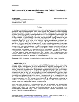
  • 9. Hiroyuki Sato International Journal of Intelligent Systems and Applications in Robotics (IJRA),Volume(10) : Issue(1) : 2021 ISSN: 2180-1312, https://www.cscjournals.org/journals/IJRA/description.php 9 (d) Calculate the average of the slopes of the remaining partial road boundary lines on each of the left and right sides, and judge that the partial road boundary lines that are a certain amount away (specifically, less than half or more than double) from the average are wrong. The boundary edges corresponding to the partial road boundary lines judged to be wrong are deleted, and the left and right road boundary lines are generated from the remaining boundary edges. FIGURE 7 shows an example. Since the partial road boundary lines of the left two areas have different characteristics from the partial road boundary lines of the other areas, the boundary edges of these areas have been deleted. As a result, the intersection of the left and right road boundary lines is almost the center of the road. (a) Removing of partial border (b) Partial border & captured image FIGURE 7: Removal of incorrect boundary. 5. EXPERIMENTAL RESULTS When the above improvements were made and the vehicle was run in the same environment as Section 3.3, it was possible to complete the 100m road, which was a considerable improvement compared to the average mileage of 10m before the improvement. Therefore, it was confirmed that the purpose of this study was achieved. The purpose is to build an algorithm that can control the running of the AGV with only the information input from one camera, and to operate it with sufficient performance and accuracy on the processor installed in the mobile terminal. Verification on the test course revealed that the improvement was effective. Therefore, we quantitatively evaluated how much noise removal and removal of wrong road boundaries were effective for stable running of AGV. The evaluation was performed as follows. We manually pushed the AGV equipped with the tablet PC to move it forward on the straight road in the factory and took the image in front at 1 second intervals. During this taking image, the AGV was advanced straight toward the destination in order to keep the driving direction constant. In this experiment, 108 images were taken. Then, for each of these 108 images, the following six types of travel control methods were used to calculate the travel direction per second, and to obtain the difference from the ideal travel direction. This difference was the number of pixels on the screen. (1) A method that removes noise and the wrong road boundaries (improved method). (2) A method that does not improve anything (method before improvement). (3) A method that only removes noise. (4) A method that only removes the wrong road boundaries. (5) A method that masks the floor surface instead of noise removal. (6) A method that masks the floor surface instead of noise removal and removes the wrong road boundaries. TABLE 1 shows the specifications of the tablet PC used for the measurement, and TABLE 2 shows the measurement results. In addition, FIGURE 8 shows the loci in all traveling directions (traveling from left to right in the figure) of each method and the running control results at 70 seconds from the start.
  • 10. Hiroyuki Sato International Journal of Intelligent Systems and Applications in Robotics (IJRA),Volume(10) : Issue(1) : 2021 ISSN: 2180-1312, https://www.cscjournals.org/journals/IJRA/description.php 10 It can be seen that the difference (error) between the traveling direction calculated by the control method and the ideal value is small for (1) the improved method. Compared to (2) the methods before the improvement, the average error is reduced to 20%, the maximum error is reduced to 21%, and the variation in the traveling direction is reduced to 1.4%. From these facts, it can be seen that our proposal improvement is very effective. TABLE 1: Specification of tablet PC used for measurement. TABLE 2: Measurement results. Next, regarding the effect of each improved method, the effect of removing the wrong road boundaries is higher, because (4) is better than (3). However, it can be seen that the synergistic effect of both is high, because the accuracy of (4) is considerably lower compared to the case of (1) where both improvements are applied. From the results of (5) and (6), it is found that the effect of removing noise on the floor surface by mask processing is quite high. The variance is small because the boundary of the mask is located near the road boundary and there is no major failure in road boundary detection. This experiment went well because it was carried out on an almost straight road, but if there is a gentle curve, there is a risk that the road boundary will disappear due to the mask, so it is difficult to use the mask in practice. The processing time has increased by about 40 milliseconds from before the improvement, but it is about 250 milliseconds, which is a time that does not hinder the running control every second. From the comparison of (2) and (3), it can be seen that the 40 milliseconds of the increment is mostly due to noise removal. Note that applying a mask to the floor shortens the processing time, because edge detection is not performed inside the mask. The maximum value of the difference (error) between the traveling direction and the ideal value calculated by the proposed method (1) is 68 dots from TABLE 2. It means that there was a deviation of about 0.5 m from the load width of 5 m, since this is about 10% of the width of the screen of 640 dots. It was found that it is possible to drive without hitting the wall if the road is about 1.5 m, since the width of the AGV is about 50 cm. Actually, we couldn't drive well in the road with a width of about 1.2m. Product Name ASUS ZenPad 8.0 (Z380M) OS Android 6.0.1 CPU MediaTek MT8163 Processor 1.3GHz Main Memory 2GB Display 8-inch wide TFT color (1,280x800) Web Camera Front: 500 pixels, Rear: 2 million pixels Sensor GPS, acceleration, light, magnetism, electronic compass Communication IEEE802.11a / b / g / n, Bluetooth R 4.0 Driving time about 8 hours Size 123mm × 209mm × 8.5mm Weight about 350g Method Difference from ideal value (pixels) Processing Time (ms) Average MAX Variance (1) 19.60 68 201 252 (2) 99.08 323 14,429 213 (3) 47.77 323 6,596 251 (4) 37.27 291 2,434 213 (5) 22.92 69 181 131 (6) 23.39 71 196 131
  • 11. Hiroyuki Sato International Journal of Intelligent Systems and Applications in Robotics (IJRA),Volume(10) : Issue(1) : 2021 ISSN: 2180-1312, https://www.cscjournals.org/journals/IJRA/description.php 11 (1) Improved method (Removing noise & wrong road boundaries) (2) Before improvement (3) Removing only noise
  • 12. Hiroyuki Sato International Journal of Intelligent Systems and Applications in Robotics (IJRA),Volume(10) : Issue(1) : 2021 ISSN: 2180-1312, https://www.cscjournals.org/journals/IJRA/description.php 12 (4) Removing only wrong road boundaries (5) Masking floor surface (6) Masking floor surface & removing wrong road boundaries FIGURE 8: Whole traveling trajectories and driving control result at 70 seconds of each method
  • 13. Hiroyuki Sato International Journal of Intelligent Systems and Applications in Robotics (IJRA),Volume(10) : Issue(1) : 2021 ISSN: 2180-1312, https://www.cscjournals.org/journals/IJRA/description.php 13 6. CONCLUSIONS We mounted a tablet PC on an AGV (automated guided vehicle) used in a manufacturing plant, and autonomous driving control was performed by image processing. In this research, we built an algorithm that can control the running of AGV with only the information input from one camera, and verified whether it operates with sufficient performance on the processor installed in the mobile terminal (tablet PC). It was found that the problems of driving accuracy were the influence of floor noise and the detection of wrong road boundaries. We removed the noise on the floor by a method that took advantage of the features of the image, and reduced the detection of wrong road boundaries by making improvements to better methods of road boundary detection. With these two improvements, we were able to complete the AGV, which previously only advanced about 10m, to the final 100m of the test course. As a result of the measurement, the average error in the traveling direction was reduced to 20%, the maximum error was reduced to 21%, and the variation in the traveling direction was reduced to 1.4%. From these, it was shown that the improvement of this proposal was very effective. The processing time has increased by about 40 milliseconds from before the improvement, but it is about 250 milliseconds, which is a time that does not hinder the running control every second. In the experiment, a maximum deviation of about 0.5 m occurred, so it was found that the vehicle can run if the road width is about 1.5 m. However, this method can be applied to only straight paths (no problem if it is a gentle curve), and another method (Haginiwa et al., 2015) using a sign is adopted for turning at a corner. Furthermore, in narrow passages that require precise running control, we adopt conventional running with magnetic tape. Therefore, for practical use in the future, it is necessary to make a comprehensive control method that can switch between the method proposed this time, control using signs, and control using magnetic tape. We found that the mobile terminal can be applied to embedded systems by adopting a relatively simple control method in our proposal, and achieved our research purpose. It is possible to build a system that is easy to use even for users who are unfamiliar with computers working on the manufacturing plant line, since the tablet PC has an interface similar to that of a smartphone. In the future, we will consider applying mobile terminals to various control systems in such an environment. 7. REFERENCES Chen, Q.M., Dong, C.Y., Mu, Y. Z., Li, B.C., Fan, Z. Q., & Wang, Q. L. (2020). An Improved Particle Filter SLAM Algorithm for AGVs. 2020 IEEE 6th International Conference on Control Science and Systems Engineering (ICCSSE), 27-31. Chen, Y., Wu, Y., & Xing, H. (2017). A complete solution for AGV SLAM integrated with navigation in modern warehouse environment. 2017 Chinese Automation Congress (CAC), 6418- 6423. Chuixin, C., & Hanxiang, C. (2019). AGV Robot Based on Computer Vision and Deep Learning. 2019 3rd International Conference on Robotics and Automation Sciences (ICRAS), 28-34. Durrant-whyte, H. (2006). Simultaneous Localization and Mapping (SLAM): Part I The Essential Algorithms. Robotics and Automation Magazine, 13(2), 99-110. Haginiwa, A., & Sato, H. (2015). Image recognition of signs and applying at intersections in autonomous driving AGV (in Japanese). IEICE Technical report, 115(270), 45-50. Hashiba, M., Yoshikawa, T., & Suzuki, S. (2002). Self-position identification method for indoor mobile robots using image information (in Japanese). Report of Hokkaido Industrial Research Institute, 301, 9-15.
  • 14. Hiroyuki Sato International Journal of Intelligent Systems and Applications in Robotics (IJRA),Volume(10) : Issue(1) : 2021 ISSN: 2180-1312, https://www.cscjournals.org/journals/IJRA/description.php 14 Kamewaka, S., & Uemura, S. (1987). A magnetic guidance method for automated guided vehicles. IEEE Transactions on Magnetics, 23(5), 2416-2418. Kawabe, M., Takahata, K., & Ueda, Y., (1996). Automatic generation of indoor road map for autonomous mobile robots (in Japanese). 1996 IEICE general conference, D-592. Lee J., Hyun C.H., & Park M. (2013). A Vision-Based Automated Guided Vehicle System with Marker Recognition for Indoor Use. Sensors 2013, 13, 10052-10073. Li, ., & Schulze, L. (2018). Comparison and Evaluation of SLAM Algorithms for AGV Navigation. In F.-J. Villmer, E. Padoano, & Department of Production Engineering and Management (Eds.), Production Engineering and Management, 213–223. Martinez-Barbera, H., & Herrero-Perez, D. (2010). Autonomous navigation of an automated guided vehicle in industrial environments. Robotics and Computer-Integrated Manufacturing, 26(4), 296-311. Nagae, G., Watanabe, K., Muramatsu, E., Ariga, Y., & Endo, S. (2008). Autonomous driving control of electric wheelchair by image processing and sensor (in Japanese). The 245th meeting of the Tohoku Branch of the Society of Instrument and Control Engineers, 245(5). Sabikan, S., Sulaiman, M., Najib, S., & Miskon, M.F.B. (2010). Vision Based Automated Guided Vehicle for Navigation and Obstacle Avoidance. 2nd International Conference on Engineering and ICT, Malacca, Malaysia, 18-20. Sant Ana, P. M., Marchenko, N., Popovski ,P., & Soret, B. (2020). Wireless Control of Autonomous Guided Vehicle using Reinforcement Learning. GLOBECOM 2020-2020 IEEE Global Communications Conference, 1-7. Shi, E., Huang, Y., & Lin, Y. (2004). Research on the method of composite navigation for AGV. IEEE Fifth World Congress on Intelligent Control and Automation, 6, 4987-4990. Sierra-García, J. E., & Santos, M. (2020). Control of Industrial AGV Based on Reinforcement Learning. 15th International Conference on Soft Computing Models in Industrial and Environmental Applications (SOCO 2020), 647-656. Singh, M.P.. & Jain M.K. (2014). Evolution of Processor Architecture in Mobile Phones. International Journal of Computer Applications, 90(4), 34-39. Smieszek, M., Dobrzanska, M., & Dobrzanski, P. (2015). Laser navigation applications for automated guided vehicles. Measurement Automation Monitoring, 61(11). Tanabe, T., Umino, K., & Sakurai, H. (2008). Examination of robot movement control using image processing (in Japanese). KEK Proceedings, 2008(3), 277-286. Tsumura, T. (1986). Survey of Automated Guided Vehicles in Japanese Factory. International Conference on Robotics and Automation, 1329-1334. Vis, I.F.A. (2006). Survey of research in the design and control of automated guided vehicle systems. European Journal of Operational Research, 170(3), 677-709. Wang, Tc., Tong, Cs. & Xu, Bl. (2020). AGV navigation analysis based on multi-sensor data fusion. Multimed Tools Appl 79, 5109–5124.
  • 15. Hiroyuki Sato International Journal of Intelligent Systems and Applications in Robotics (IJRA),Volume(10) : Issue(1) : 2021 ISSN: 2180-1312, https://www.cscjournals.org/journals/IJRA/description.php 15 Yu, J., Lou, P., & Wu, X., (2009). A Dual-Core Real-Time Embedded System for Vision-Based Automated Guided Vehicle. International Conference on Control, Automation and Systems Engineering, 207-211. Zhou, S., Cheng, G., Meng, Q., Lin, H., Du, Z., & Wang, F. (2020). Development of multi-sensor information fusion and AGV navigation system. 2020 IEEE 4th Information Technology, Networking, Electronic and Automation Control Conference (ITNEC), 2043-2046. Zhou, X., Chen,T., & Zhang, Y. (2018). Research on Intelligent AGV Control System. 2018 Chinese Automation Congress (CAC), 58-61.