Optimizing Electrical Efficiencyand Reducing Costs
Automatic Power Factor Control (PFC)
Presented by: Ankan Bhattacharya, Priyanka Dey, Pradyut Mondal,
Soheli Saha, Biswajit Mondal, Srijan Banik
Under the supervisition of Mrs. Kastori Gon
Department of Electrical Engineering
Birla Institute of Technology
56. B. T. Rode, Kolkata-700050, West Bengal
West Bengal State Counsil & Vocational
Education & Skill Development
2.
Introduction
Definition ofPower Factor:
It is defined as cosine of the angle between voltage and current phases
It can also be defined as ratio of actual power (KW) and apparent power (KVA) .
Represents how efficiently electrical power is being used.
Real Power (kW): The actual power consumed by
electrical devices to perform work
Reactive Power (kVAR): The power required to
maintain the magnetic field in inductive loads
Apparent Power (kVA): The total power supplied to
the circuit, including both real and reactive power
Why Power Factor Control is Important:
Reduces energy losses and inefficiencies.
Helps avoid penalties from utility companies for low power
factor.
Improves the overall performance of electrical systems.
3.
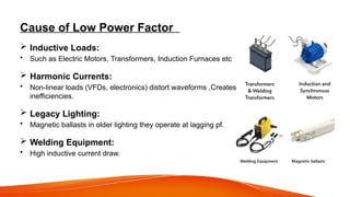
Cause of LowPower Factor
Inductive Loads:
• Such as Electric Motors, Transformers, Induction Furnaces etc
Harmonic Currents:
• Non-linear loads (VFDs, electronics) distort waveforms ,Creates
inefficiencies.
Legacy Lighting:
• Magnetic ballasts in older lighting they operate at lagging pf.
Welding Equipment:
• High inductive current draw.
4.
Effects of LowPower Factor
Increased Transmission Losses:
• More power is wasted in transmission lines, reducing overall system efficiency.
Higher Electricity Bills:
• Utilities charge penalties for poor power factor, leading to increased operational costs.
Equipment Overloading:
• Electrical equipment such as transformers and generators need to handle higher apparent
power, reducing their lifespan.
Reduced System Efficiency:
• Poor power factor causes voltage drops and inefficient energy usage, affecting overall
productivity.
Unstable Voltage Levels:
• Fluctuations in voltage can damage sensitive electrical equipment and lead to operational
disruptions.
5.
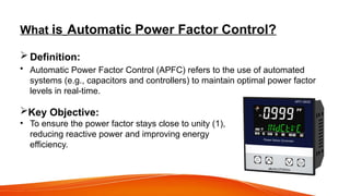
What is AutomaticPower Factor Control?
Definition:
• Automatic Power Factor Control (APFC) refers to the use of automated
systems (e.g., capacitors and controllers) to maintain optimal power factor
levels in real-time.
Key Objective:
• To ensure the power factor stays close to unity (1),
reducing reactive power and improving energy
efficiency.
6.
How Automatic P.F.Control Works
Monitoring:
• Continuous real-time monitoring of power factor, voltage, and current.
Data Processing:
• A controller analyzes this data and determines whether capacitors need to be switched in or
out.
Adjustment:
• Capacitor banks are automatically switched on or off to correct the power factor.
Feedback:
• The system keeps adjusting to changing load conditions, maintaining optimal efficiency.
7.
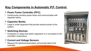
Key Components inAutomatic P.F. Control
Power Factor Controller (PFC):
• Continuously monitors power factor and communicates with
capacitor banks.
Capacitor Banks:
• Large or small capacitors that provide reactive power to the
system.
Switching Devices:
• Contactors or relays that switch capacitors in or out based on the
controller’s instructions.
Current and Voltage Sensors:
• Measure the electrical parameters and provide data to the
controller.
8.
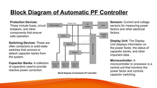
Block Diagram ofAutomatic PF Controller
Microcontroller: A
microcontroller or processor is a
central unit that monitors the
power factor and controls
capacitor switching.
Capacitor Banks: A collection
of capacitors used to provide
reactive power correction.
Switching Devices: These are
often contactors or solid-state
switches that connect or
detach capacitor banks from
the system.
Sensors: Current and voltage
sensors for measuring power
factors and other electrical
factors.
Display Unit: The Display
Unit displays information on
the power factor, the status of
capacitor banks, and other
important data.
Protection Devices:
These include fuses, circuit
breakers, and other
components that ensure
safe operation.
9.
Benefits of AutomaticPower Factor Control
Cost Savings:
• Avoid penalties from the power utility for low power factor.
Energy Efficiency:
• Ensures efficient energy usage by reducing reactive power.
Reduced Losses:
• Minimizes energy losses in transformers and distribution equipment.
Equipment Protection:
• Protects generators, transformers, and other electrical components from strain.
System Stability:
• Maintains voltage stability and reduces fluctuations.
10.
Advantages of Automationin PFC
Dynamic Adjustment:
• Automatically adjusts to changing load conditions, which manual systems
cannot do.
Optimal Compensation:
• Provides just the right amount of reactive power, avoiding overcompensation
or undercompensation.
Reduced Maintenance:
• Automated systems require less manual intervention and are more reliable.
Improved System Performance:
• Enhances the efficiency and performance of the entire electrical system.
11.
Automation Algorithms inPower Factor Control
Controller Algorithms:
• These algorithms continuously adjust the capacitors based on the load
conditions.
• Examples include open-loop control, closed-loop control, and fuzzy logic
controllers.
Real-Time Data Integration:
• Use of real-time data to predict and manage future load changes and power
factor shifts.
12.
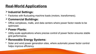
Real-World Applications
IndustrialSettings:
• Factories with fluctuating machine loads (motors, transformers).
Commercial Buildings:
• Office complexes, malls, and data centers where power factor needs to be
optimized.
Power Plants:
• Utility-scale applications where precise control of power factor ensures stable
grid performance.
Renewable Energy Systems:
• Solar and wind power generation sites, where automatic power factor control
helps improve efficiency.
13.
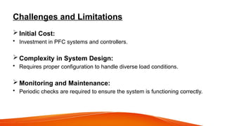
Challenges and Limitations
Initial Cost:
• Investment in PFC systems and controllers.
Complexity in System Design:
• Requires proper configuration to handle diverse load conditions.
Monitoring and Maintenance:
• Periodic checks are required to ensure the system is functioning correctly.
14.
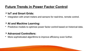
Future Trends inPower Factor Control
IoT and Smart Grids:
• Integration with smart meters and sensors for real-time, remote control.
AI and Machine Learning:
• Predictive models to optimize power factor control based on historical data.
Advanced Controllers:
• More sophisticated algorithms to improve efficiency even further.
15.
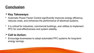
Conclusion
Key Takeaways:
•Automatic Power Factor Control significantly improves energy efficiency,
reduces costs, and enhances the performance of electrical systems.
• It is critical for industries, commercial buildings, and utilities to implement
PFC for cost-effectiveness and system stability.
Call to Action:
• Encourage businesses to adopt automated PFC systems for long-term
energy savings.


![Organic presentation ENERGY EFFICIENT MOTOR[1][1][1].pptx](https://cdn.slidesharecdn.com/ss_thumbnails/organicpresentationenergyefficientmotor111-260112104953-fd35734a-thumbnail.jpg?width=640&height=640&fit=bounds)


