Download to read offline
![2 M. Padsumbiya et al./ Journal of Soft Computing in Civil Engineering 6-3 (2022) 01-17
1. Introduction
The maintenance of any building is followed by a set plan of timely inspections and maintenance
work to increase the life span of the building. A building undergoes deterioration due to multiple
external and internal factors. Cracks are an important aspect of any structure as they provide a
visual signal to the distress of that structure. Hence, inspecting and evaluating cracks is one of
the most important steps to predicting the life span of any structure [1]. However, manual
inspection leads to reliability and accessibility issues, heavy reliance on inspectors leading to
manual errors compounded with financial issues [2].
To avoid the cons of manual inspection, advanced technologies can be used for automatic crack
detection and the academic community has been fairly excited about this. Barrias et al., proposed
crack measuring systems using fiber optic sensors by implanting IoT based sensors for the
surface under scrutiny [3]. Feng et al., proposed the route of using a laser scanning system that
generates a high-density 3D point cloud for better accuracy in crack detection [4]. Yan et al.
proposes the use of a novel sensing skin that identifies change in strain over a surface and detects
cracks [5]. Similarly, Downey et al. further proposed a Monte Carlo method for using high value
resistors in resistor mesh model to detect the electrical output from self-sensing material [6]. Kim
et al. proposes the use of images from a combination of RGB-D and high-resolution digital
cameras in a sensor fusion algorithm [7]. Cho et al. proposes the use of image processing
algorithms on octree data from Terrestrial laser scanning [8].
The robustness of Machine learning techniques enables its use to address different Civil
Engineering problems. Farhangi.et al. uses Artificial Neural Networks for better accuracy in
estimating the first yield point displacement and post-yield stiffness ratio in shape memory alloy
equipped bar hysteric dampers [9]. Khaleghi et al. uses a novel Multi-pier method to determine
the behavior of Perforated unreinforced masonry walls. The results of Multi-pier method are
used for predictive analysis of Perforated unreinforced masonry walls using various Machine
learning techniques [10]. Chen. et al. proposes the use of multi-source sensor information to
form fused RGB-thermal images for pavement damage detection using the pre-trained Efficient
Net B4 model. The results of the model provide high accuracy even with complex pavement
conditions [11].
Advancements in deep learning techniques and the currently used cumbersome rehabilitation and
maintenance techniques call for applying deep learning techniques in Civil engineering. Deep
learning is a branch of machine learning with applications in image classification, natural
language processing [12]. Image classification can be convenient in crack detection as computer
efficiency and advanced algorithmic tools can be leveraged to understand low-level patterns in
cracked concrete surfaces. With its immensely optimized structure and more minor
computational needs, deep learning, not to forget the accuracy, gives it an upper hand over other
machine learning techniques when it comes to image classification [2].
Using vision-based approaches to provide a solution to automatic crack detection is under lot of
consideration by many researchers around the world. O’Byrne et al. proposes the use of
segmentation techniques and texture analysis for detecting damage detection in structures [13] .](https://image.slidesharecdn.com/sccevolume6issue3pages1-17-250521085932-9ef20f1b/85/Automatic-Crack-Detection-Using-Convolutional-Neural-Network-2-320.jpg)
![M. Padsumbiya et al./ Journal of Soft Computing in Civil Engineering 6-3 (2022) 01-17 3
Kalfarisi et al. proposes the use of Deep Learning techniques with a 3D mesh model for
segmentation and detection of cracks [14]. Li et al. proposes a novel Fully Convolutional Neural
network which in steps measure the features of cracks [15]. Gao et al. prove the effectiveness of
deep Transfer learning based models for structural damage recognition [16]. Fang et al. proposed
the use of a hybrid model by combining a Faster Region-Based Convolutional Neural Network
for crack patch detection, a Convolutional Neural Network for crack orientation recognition, and
a Bayesian algorithm [17] . Sattar et al. compares Edge Detectors and Deep Convolutional
Neural Networks for image-based crack detection and concludes that convolutional neural
networks perform much better both in terms of accuracy and efficiency [18].
In this paper, the problem of crack detection is addressed with the use of a Convolutional Neural
Network scaled down to work on 128x128x3 px images for better efficiency. The model is
proposed to detect cracks and automatically classify images of concrete surfaces with/without
cracks. It is crucial to understand the underlying concepts of deep learning and what happens
under the hood of any neural network. A comprehensive explanation of the same is given to build
both an intuitional understanding and mathematical understanding of neural networks for the
convenience of any reader not equipped with the proper understanding of deep learning
techniques. Finally, the procedure and results of the experimental work are presented. The
differing pixel values of grayscale cracked area of the image and background of the image allows
segmentation and detection of cracks in an image. The results of the model are promising and are
fully viable for practical uses.
2. Research significance
Researchers around the world have come up with significantly accurate solutions to Automatic
crack detection by using Deep Learning techniques. This enables high efficiency and less costs
for structural damage detection when compared to other techniques both Automatic and Manual.
However, the solutions are extremely complex. Moreover, the architecture of any neural network
is such that as the network becomes larger and complex, the number of parameters increase
drastically, further plummeting crack detection speeds [19]. This study proposes the use of a
simple 4 layered convolutional neural network enabled to detect cracks from a 128*128*3
image. This increases efficiency and eliminates the need for high-end costly devices to capture
complex digital data for training the model and significantly improves prediction speeds.
3. Literature review
3.1 Deep learning
Deep learning takes on many different applications in fields ranging from biomedical to
astronomy to different engineering domains. The availability of large amounts of data and faster
algorithms, not to mention the development of efficient computational technology, has made
using deep learning techniques in artificial intelligence even more successful. Computer vision
remains one of the best most popular, and many people worldwide are interested in learning
more about it. However, computer vision being analogical with the human visual cortex was first](https://image.slidesharecdn.com/sccevolume6issue3pages1-17-250521085932-9ef20f1b/85/Automatic-Crack-Detection-Using-Convolutional-Neural-Network-3-320.jpg)
![4 M. Padsumbiya et al./ Journal of Soft Computing in Civil Engineering 6-3 (2022) 01-17
thought of in the 1940s. Back then, it was called cybernetics, the main goal being the
computation of a linear function. In the 1980s, it was named connectionism, and
backpropagation was introduced by Rumelhart et al. in 1986 [20,21]. However, unlike today, the
idea of backpropagation was not utilized for all layers of the neural network. With the work of
Hinton et al. in 2006, it was renamed Deep Learning [22]. Hinton et al. solved the problem of the
unfeasibility of neural networks by developing the idea of pre-training and fine-tuning. Since
then, the availability of large data sets, better computational power, efficient algorithms, and
better cleaner data Deep Learning has proved to be the most sought-after technique for computer
vision areas [23–25]. The availability of better graphics, GPUs, and open-source frameworks
making the execution of models easier, has further motivated Deep Learning techniques.
Different Deep Learning techniques- Deep Belief Networks, Convolutional Neural Networks,
Recurrent Neural Networks, Feed-Forward, Fully Connected Neural Networks- are better suited
for different applications.
3.2 Mathematical understanding
Forward propagation is the first real sub-task of a deep learning model where the input is passed
through the convoluted layers to learn features, and learned features are passed through feed-
forward fully connected layer/s to compute loss. The main goal of forwarding propagation is to
get an output using the input features in such a way as to minimize the cost (difference between
output labels and predicted labels) by tweaking the hyperparameters that lead to an optimized set
of weights and bias vectors [26]. The overall idea is then to learn the weights and biases over a
series of iterations. In mathematical terms, the goal is to predict the output of function y = f (x,
𝜽�), where y is the output label, x is the input data, and 𝜽� are parameters whose values are
learned. There can be multiple layers executing the same process where the output of the
preceding layer acts as the input. When multi-layered, it is called a network. Each layer in any
such network has its function and parameters. In the case of a Convoluted layer, these weights
and biases form a kernel. Convoluted layers are best at detecting features. Usually, the
convoluted layers precede the feed-forward, fully connected layers. At every convoluted layer,
the kernel with randomly initialized weights and chosen dimensions is operated over the first
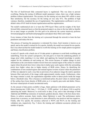
data instance. The kernel undergoes matrix multiplication over the input matrix pixel by pixel
according to stride value. The output of each instance of matrix multiplication is stored in the
output matrix. Subsequently, the output matrix is passed through an activation function and a
pooling function, if any. This follows all convoluted layers where the output from the preceding
layer acts as input for any subsequent layer. The dimensions of the output matrix from any
convoluted layer can be derived using:
𝑛[𝐿]
= ((𝑛[𝐿−1]
+ 2𝑝 − 𝑓)/𝑠) + 1 (1)
Where n[L]
is the dimensions of data for the current layer, n[L-1]
is the dimensions of data for the
previous layer, p is the padding value implied on the previous layer, f is the dimensions of
kernel/filter applied on the previous layer, s is the stride value implied on the previous layer. It is
important to note that the output value of dimensions from the above formula before any pooling
is applied on the previous layer. If pooling is applied, the dimensions are further reduced. The](https://image.slidesharecdn.com/sccevolume6issue3pages1-17-250521085932-9ef20f1b/85/Automatic-Crack-Detection-Using-Convolutional-Neural-Network-4-320.jpg)
![M. Padsumbiya et al./ Journal of Soft Computing in Civil Engineering 6-3 (2022) 01-17 5
last convoluted layer is succeeded by a flattening layer where the matrix is flattened to pre-
process the data for a fully connected layer.
At a fully connected layer, the basic mathematical calculation is a multiplication of input features
with weights layer by layer and the addition of biases. The result is passed through an activation
function, the result being promoted as inputs for the next layer.
𝑍[1]
=
(
𝑊1
1
𝑊2
1
𝑊1
2
𝑊2
2
𝑊3
1
⋯ 𝑊4
1
𝑊3
2
⋯ 𝑊4
2
𝑊1
3
𝑊2
3
𝑊1
4
𝑊2
4
𝑊3
3
⋯ 𝑊4
3
𝑊3
4
⋯ 𝑊4
4
)
(
𝑋1
𝑋2
𝑋3
𝑋4
⋮
⋮
𝑋 )
�+�(
𝑏1
𝑏2
𝑏3
𝑏4
) (2)
A[1]
= σ (
Z[1]1
Z[1]2
Z[1]3
) = (
A[1]1
A[1]2
A[1]3
) (3)
At the output layer, the activation function gives predictions. These predictions are then
compared to true labels, and the competency is checked using a loss function which can be
defined as L (Y, Ŷ), where Y depicts the predictions and Ŷ depicts true labels. The losses are
decreased through consecutive backpropagation operations, each of which modifies the
hyperparameters to lower the losses. This can be achieved by finding Cost Function gradients
with respect to weights and biases at each layer. This is the entire process of a convolutional
neural network in a nutshell and an overview of how it performs.
3.3 Recent work
Extensive research for use of Deep Learning models for crack detection has provided promising
results in the recent past. Guo X.Hu et al. [27] discuss the use of YOLOv5 series pre-trained
models for pavement crack detection on an image dataset captured using a high-end digital
camera, and reach a promising 88.1% accuracy, although on 2978 x 3978 pixel images. Pang-jo
Chun et al. [28] proposes the use of Light Gradient Boosting Machine model for automatic crack
detection and compare the results with pix2pix-based approach. The study generates crack
features using pixel values and geometric shapes and achieves an accuracy of 99.7%, whilst
being a complex procedure. Yang Yu et al. [29] critiques the accuracy and computational cost of
automatic crack detection techniques currently used. They propose a vision-based crack
detection method using Deep Learning and the Enhanced Chicken Swarm algorithm. Diane
Andrushia A et al. [30] propose a Deep Learning model for crack detection on concrete surfaces
exposed to elevated temperatures. The proposed method performs pixel wise classification using
a complex U-Net architecture with a encoder and decoder framework. Abdellah Chehri et al. [31]
presents an IoT and Deep Learning based solution for automatic crack detection on Concrete
Bridge Structures. Weijian Zhao et al. [32] proposes a combination of YOLOv5 model and crack
feature pyramid network (Crack-FPN) for reduced computational cost and feature extraction.
Munawar, H.S et al. [33] conduct a review on 30 different crack detection models proposed in](https://image.slidesharecdn.com/sccevolume6issue3pages1-17-250521085932-9ef20f1b/85/Automatic-Crack-Detection-Using-Convolutional-Neural-Network-5-320.jpg)
![6 M. Padsumbiya et al./ Journal of Soft Computing in Civil Engineering 6-3 (2022) 01-17
the past decade. The study advocates for the consideration of computational costs, resource
consumption, and applicability in real-time scenarios. This study addresses these factors in the
proposed crack detection model.
In this paper, a combination of convoluted layers and feed-forward neural layers is used for
image classification. With a motive to achieve better results and computational efficiency,
appropriate optimization techniques have been used. The simplistic architecture of the model,
making it robust and providing more scope for further changes to accommodate further aims,
makes the model one of a kind. Also, this paper is written to accommodate a reader with lesser or
no knowledge of deep learning models, explaining what happens under the hood. In all, a model
has two sub-tasks- forward propagation and backward propagation. The sub-tasks are linked so
that forward-propagation generates a prediction, which is then compared to the true value using a
loss function. The difference in the true value and prediction loss is used by backward
propagation to tweak the parameters to reduce this difference. Specifically, the convoluted layers
detect and learn the features.
4. Methods
Crack detection in the current scenario for most parts of the world is a tedious job and is often
prone to human errors. It is inherently time-consuming. A neural network model is being
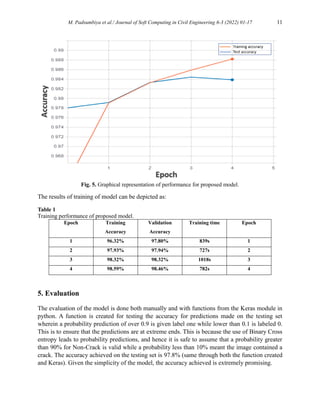
proposed here to automate the task of crack detection. The proposed model has an accuracy of
97.8%.
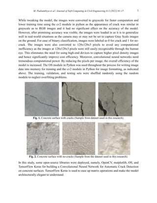
The proposed model uses a total of 40,000 images of concrete surfaces extracted from an open-
source platform [34]. The data is created and uploaded by Çağlar Fırat Özgenel. Many thanks to
Çağlar Fırat Özgenel for contributing such refined images. The dataset contains 20,000 images
with cracks and 20,000 images with no cracks over the concrete surface. The cracks present in
the images are of varied form, shape, and nature, so diversity is taken care of. The images are
generated from 458 high-resolution images of 4032*3024 pixels with the method Zhang et al.
[25]. High-resolution images have variance in surface finish and illumination conditions, making
the model applicable to robust conditions. The shape of each instance of data is 227*227*3 with
RGB channels. Fig. 1 and fig. 2 illustrates sample images used for training the model. A total of
32400 images were randomly chosen for training the model, 3600 images were randomly chosen
for validation purposes and 4000 images were separated for testing the model. Because the size
and diversity in the training set and testing set are enough for the model to give satisfactory
results, no data augmentation in random rotation or flipping is applied. An equilibrium in the
distribution of all training, validation, and testing sets was maintained to ensure that a similar
number of images labeled crack and non-crack is present to avoid bias. 16200, 1800, and 2000
images of crack and non-crack concrete surfaces are set in training, validation, and testing sets,
respectively. It was also ensured that no image was repeated in training, validation, or testing
sets.](https://image.slidesharecdn.com/sccevolume6issue3pages1-17-250521085932-9ef20f1b/85/Automatic-Crack-Detection-Using-Convolutional-Neural-Network-6-320.jpg)
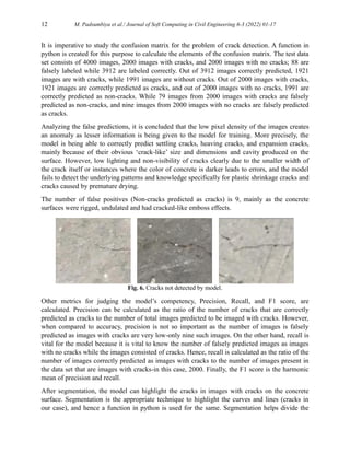
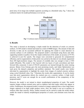
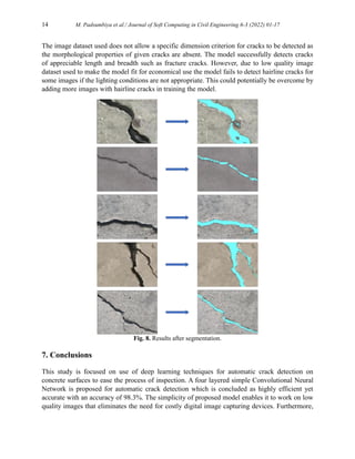
![M. Padsumbiya et al./ Journal of Soft Computing in Civil Engineering 6-3 (2022) 01-17 15
the model is able to successfully segment cracks which are mostly major cracks with visible
dimensions such as settling cracks, heaving cracks, and expansion cracks. However, the model
struggles to detect minor cracks such as plastic shrinkage cracks and cracks caused by premature
drying. Hence, the proposed model can be used for quick initial inspection to detect major cracks
on concrete surfaces.
8. Future trends
A convolutional neural network model is proposed in this project for automatic crack detection
on concrete surfaces. The simplicity of this model can be leveraged for use in real-time for the
automatic assessment of structural damage. The model struggles to detect minor cracks due to
external factors which can potentially be eliminated by training the model on more data.
Furthermore, various techniques can be equipped to detect the morphological and physical
properties of cracks, and predict the urgency for repairs. Future scope of this study will be
focused on enabling the model for, detecting different types of surface distresses and use on all
types of surfaces.
Funding
This research received no external funding.
Conflicts of interest
The authors declare no conflict of interest.
References
[1] Avendaño J. Identification and quantification of concrete cracks using image analysis and machine
learning. KTH VETENSKAP OCH KONST, 2020.
[2] O’ Mahony N, Campbell S, Carvalho A, Harapanahalli S, Velasco Hernandez G, Krpalkova L, et
al. Deep Learning vs. Traditional Computer Vision. n.d.
[3] Barrias A, Casas JR, Villalba S. Embedded distributed optical fiber sensors in reinforced concrete
structures - A case study. Sensors (Switzerland) 2018;18. https://doi.org/10.3390/s18040980.
[4] Feng H, Member S, Li W, Luo Z, Chen Y, Member S, et al. GCN-Based Pavement Crack
Detection Using Mobile LiDAR Point Clouds. n.d.
[5] Yan J, Downey A, Cancelli A, Laflamme S, Chen A, Li J, et al. Concrete crack detection and
monitoring using a capacitive dense sensor array. Sensors (Switzerland) 2019;19.
https://doi.org/10.3390/s19081843.
[6] Downey A, D’Alessandro A, Ubertini F, Laflamme S. Automated crack detection in conductive
smart-concrete structures using a resistor mesh model. Meas Sci Technol 2018;29.
https://doi.org/10.1088/1361-6501/aa9fb8.
[7] Kim H, Lee S, Ahn E, Shin M, Sim SH. Crack identification method for concrete structures
considering angle of view using RGB-D camera-based sensor fusion. Struct Heal Monit
2021;20:500–12. https://doi.org/10.1177/1475921720934758.](https://image.slidesharecdn.com/sccevolume6issue3pages1-17-250521085932-9ef20f1b/85/Automatic-Crack-Detection-Using-Convolutional-Neural-Network-15-320.jpg)
![16 M. Padsumbiya et al./ Journal of Soft Computing in Civil Engineering 6-3 (2022) 01-17
[8] Cho S, Park S, Cha G, Oh T. Development of Image Processing for Crack Detection on Concrete
Structures through Terrestrial Laser Scanning Associated with the Octree Structure. Appl Sci
2018;8. https://doi.org/10.3390/app8122373.
[9] Farhangi V, Jahangir H, Rezazadeh Eidgahee D, Karimipour A, Javan SAN, Hasani H, et al.
Behaviour Investigation of SMA-Equipped Bar Hysteretic Dampers Using Machine Learning
Techniques. Appl Sci 2021;11:10057. https://doi.org/10.3390/app112110057.
[10] Khaleghi M, Salimi J, Farhangi V, Moradi MJ, Karakouzian M. Evaluating the behaviour of
centrally perforated unreinforced masonry walls: Applications of numerical analysis, machine
learning, and stochastic methods. Ain Shams Eng J 2022;13.
https://doi.org/10.1016/j.asej.2021.10.026.
[11] Chen C, Chandra S, Han Y, Seo H. Deep learning-based thermal image analysis for pavement
defect detection and classification considering complex pavement conditions. Remote Sens
2022;14. https://doi.org/10.3390/rs14010106.
[12] Sarker IH. Deep Learning: A Comprehensive Overview on Techniques, Taxonomy, Applications
and Research Directions. SN Comput Sci 2021;2. https://doi.org/10.1007/s42979-021-00815-1.
[13] Byrne MO, Schoefs F, Gosh B, Pakrashi V, Analysis T, Damage B, et al. Texture Analysis Based
Damage Detection of Ageing Infrastructural Elements. Comput Civ Infrastruct Eng Wiley
2013;28:162–77.
[14] Kalfarisi R, Wu ZY, Soh K. Crack Detection and Segmentation Using Deep Learning with 3D
Reality Mesh Model for Quantitative Assessment and Integrated Visualization. J Comput Civ Eng
2020;34:04020010. https://doi.org/10.1061/(asce)cp.1943-5487.0000890.
[15] Li S, Zhao X, Zhou G. Automatic pixel-level multiple damage detection of concrete structure using
fully convolutional network. Comput Civ Infrastruct Eng 2019;34:616–34.
https://doi.org/10.1111/mice.12433.
[16] Gao YQ, Li KB, Mosalam KM, Gunay S. Deep residual network with transfer learning for image-
based structural damage recognition. 11th Natl. Conf. Earthq. Eng. 2018, NCEE 2018 Integr. Sci.
Eng. Policy, vol. 11, 2018, p. 6971–81.
[17] Fang F, Li L, Gu Y, Zhu H, Lim JH. A novel hybrid approach for crack detection. Pattern Recognit
2020;107. https://doi.org/10.1016/j.patcog.2020.107474.
[18] Dorafshan S, Thomas RJ, Maguire M. Comparison of Deep Convolutional Neural Networks and
Edge Detectors for Image-Based Crack Detection in Concrete. n.d.
[19] Qiao W, Liu Q, Wu X, Ma B, Li G. Automatic pixel-level pavement crack recognition using a deep
feature aggregation segmentation network with a scse attention mechanism module. Sensors
2021;21. https://doi.org/10.3390/s21092902.
[20] Flood I, Kartam N. Neural Networks in Civil Engineering. I: Principles and Understanding. J
Comput Civ Eng 1994;8:131–48. https://doi.org/10.1061/(ASCE)0887-3801(1994)8:2(131).
[21] Flood I, Kartam N. NEURAL NETWORKS IN CIVIL ENGINEERING. II: SYSTEMS AND
APPLICATION. J Comput Civ Eng 1994;8:149–62.
[22] Hinton G, Osindero S, Teh Y-W. A Fast Learning Algorithm for Deep Belief Nets Geoffrey.
Neural Comput 2006;1:1527–54. https://doi.org/10.7763/ijesd.2010.v1.67.
[23] Park S, Bang S, Kim H, Kim H. Patch-Based Crack Detection in Black Box Images Using
Convolutional Neural Networks. J Comput Civ Eng 2019;33:04019017.
https://doi.org/10.1061/(asce)cp.1943-5487.0000831.
[24] Hsieh Y-A, Tsai YJ. Machine Learning for Crack Detection: Review and Model Performance
Comparison. J Comput Civ Eng 2020;34:04020038. https://doi.org/10.1061/(asce)cp.1943-
5487.0000918.](https://image.slidesharecdn.com/sccevolume6issue3pages1-17-250521085932-9ef20f1b/85/Automatic-Crack-Detection-Using-Convolutional-Neural-Network-16-320.jpg)
![M. Padsumbiya et al./ Journal of Soft Computing in Civil Engineering 6-3 (2022) 01-17 17
[25] Zhang L, Yang F, Daniel Zhang Y, Zhu YJ. Road crack detection using deep convolutional neural
network. 2016 IEEE Int. Conf. Image Process., IEEE; 2016, p. 3708–12.
https://doi.org/10.1109/ICIP.2016.7533052.
[26] Hirasawa K, Ohbayashi M, Koga M, Harada M. Forward propagation universal learning network.
IEEE Int Conf Neural Networks - Conf Proc 1996;1:353–8.
https://doi.org/10.1109/icnn.1996.548917.
[27] Hu GX, Hu BL, Yang Z, Huang L, Li P. Pavement Crack Detection Method Based on Deep
Learning Models. Wirel Commun Mob Comput 2021;2021:1–13.
https://doi.org/10.1155/2021/5573590.
[28] Chun P, Izumi S, Yamane T. Automatic detection method of cracks from concrete surface imagery
using two‐step light gradient boosting machine. Comput Civ Infrastruct Eng 2021;36:61–72.
https://doi.org/10.1111/mice.12564.
[29] Yu Y, Rashidi M, Samali B, Mohammadi M, Nguyen TN, Zhou X. Crack detection of concrete
structures using deep convolutional neural networks optimized by enhanced chicken swarm
algorithm. Struct Heal Monit 2022:147592172110535.
https://doi.org/10.1177/14759217211053546.
[30] Andrushia A D, N A, Lubloy E, G PA. Deep learning based thermal crack detection on structural
concrete exposed to elevated temperature. Adv Struct Eng 2021;24:1896–909.
https://doi.org/10.1177/1369433220986637.
[31] Chehri A, Saeidi A. IoT and Deep Learning Solutions for an Automated Crack Detection for the
Inspection of Concrete Bridge Structures, 2021, p. 110–9. https://doi.org/10.1007/978-981-16-
3264-8_11.
[32] Zhao W, Liu Y, Zhang J, Shao Y, Shu J. Automatic pixel‐level crack detection and evaluation of
concrete structures using deep learning. Struct Control Heal Monit 2022;29.
https://doi.org/10.1002/stc.2981.
[33] Munawar HS, Hammad AWA, Haddad A, Soares CAP, Waller ST. Image-Based Crack Detection
Methods: A Review. Infrastructures 2021;6:115. https://doi.org/10.3390/infrastructures6080115.
[34] Özgenel F, Gönenç Sorguç A. Performance comparison of pretrained convolutional neural
networks on crack detection in buildings. ISARC 2018 - 35th Int. Symp. Autom. Robot. Constr.
Int. AEC/FM Hackathon Futur. Build. Things, International Association for Automation and
Robotics in Construction I.A.A.R.C); 2018. https://doi.org/10.22260/isarc2018/0094.](https://image.slidesharecdn.com/sccevolume6issue3pages1-17-250521085932-9ef20f1b/85/Automatic-Crack-Detection-Using-Convolutional-Neural-Network-17-320.jpg)
Manual inspection of cracks on concrete surfaces requires wholesome knowledge and depends entirely on the expertise and capabilities of the inspector. This study proposes the use of a simple Convolutional Neural Network (CNN) for automatic crack detection. A comparative approach for Automated Crack Detection is presented between Feed-Forward Fully Connected Neural Networks and CNN, focusing on the primary hyperparameters affecting the accuracy of both systems. An inclination towards CNN is concluded due to its simplicity and computational efficiency. For the purpose of this study, the input data is extracted from an open-source platform. In the second step, the images are pre-processed for obtaining low-pixel density images with the aim to get better accuracy at lower computer power. The CNN proposed uses Max Pooling and appropriate optimization techniques. The model is trained to detect and segregate cracked and non-cracked concrete surfaces through input images. The proposed model predicts and labels images with cracks on concrete surfaces and images with no cracks using pixel-level information. The final accuracy achieved is 97.8% by the proposed CNN model. The proposed model is a novel approach to detecting cracks on low pixel density images of concrete surfaces for its economic and processing efficiency and thus eliminates the need for high-cost digital image capturing devices. This study signifies and confirms the impact of Artificial Intelligence in the Civil Engineering field where using simple techniques like a simple four-layered Neural Network is capable of carrying automatic inspection of cracks which can be further developed for other applications.