Downloaded 39 times


![19
[1] Prerna Chauhan, Ritika Tripathi Jyoti Rani, "Li-Fi (Light Fidelity)-The future technology In Wireless communication," International
Journal of Applied Engineering Research, Nov 2012.
[2] M. Mutthamma, "A survey on Transmission of data through illumination - Li-Fi," International Journal of Research in Computer and,
Dec 2013.
[3] (2015) wikipedia. [Online]. http://en.wikipedia.org/wiki/Visible_light_communication
[4] Raafat Ali Ali , “Light Fidelity (Li-Fi) Technology ” Higher Institute for Applied Sciences and Technology
Communications Department 4th year, SEMINAR , April 2nd, 2015.
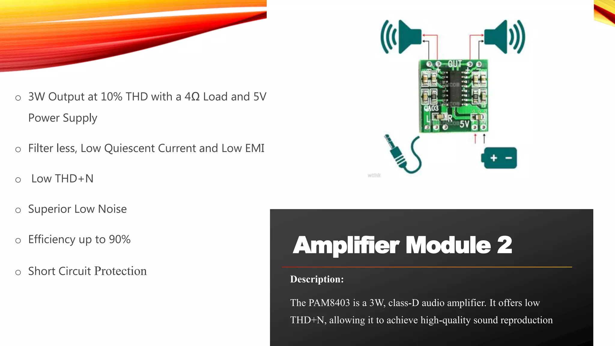
[5] https://www.diodes.com/assets/Datasheets/PAM8403.pdf
Reference](https://image.slidesharecdn.com/li-fiintro-190123161026/75/Audio-Transmission-using-LED-19-2048.jpg)


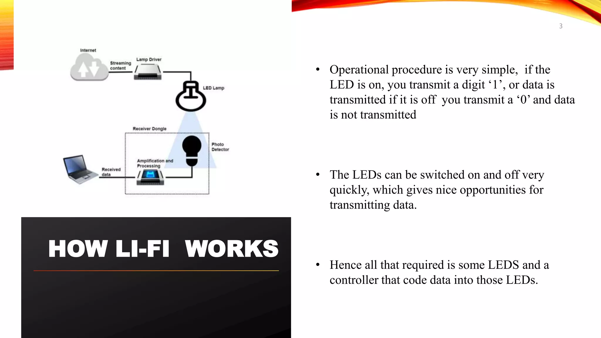
The document discusses the application of Li-Fi (Light Fidelity) for audio transmission using LED technology, which enables data transfer via light signals that are modulated faster than the human eye can perceive. It highlights the advantages of Li-Fi for underwater communication, particularly for submarines, as it operates effectively where traditional RF signals fail. The summary includes details about the operational principles of Li-Fi, the required components for a transmission and receiving system, and its potential applications in military operations.


![ppt on IC [Integrated Circuit]](https://cdn.slidesharecdn.com/ss_thumbnails/1-171227170055-thumbnail.jpg?width=640&height=640&fit=bounds)


![UNDERWATER_DATA_AND_AUDIO_TRANSMISSION_USING_LIFI_(4)[1].pptx](https://cdn.slidesharecdn.com/ss_thumbnails/underwaterdataandaudiotransmissionusinglifi41-250227021852-5c0da458-thumbnail.jpg?width=640&height=640&fit=bounds)