Download to read offline
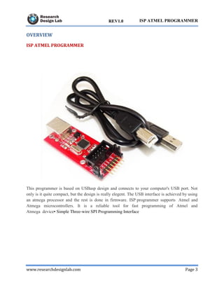
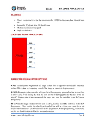
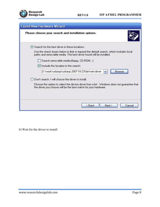

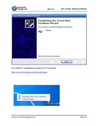


This document describes an ISP Atmel programmer that allows programming of Atmel and Atmega microcontrollers through a simple three-wire SPI interface. The programmer connects to a computer via USB and works on Windows, Mac OS, and Linux. It can read/write EEPROM, firmware, fuse bits, and lock bits at a maximum speed of 5 KB/sec. Instructions are provided on installing the necessary drivers and using the ProgISP programmer software to load hex files and program chips. The programmer can also be used with 8051 and ATmega development boards.