Download to read offline
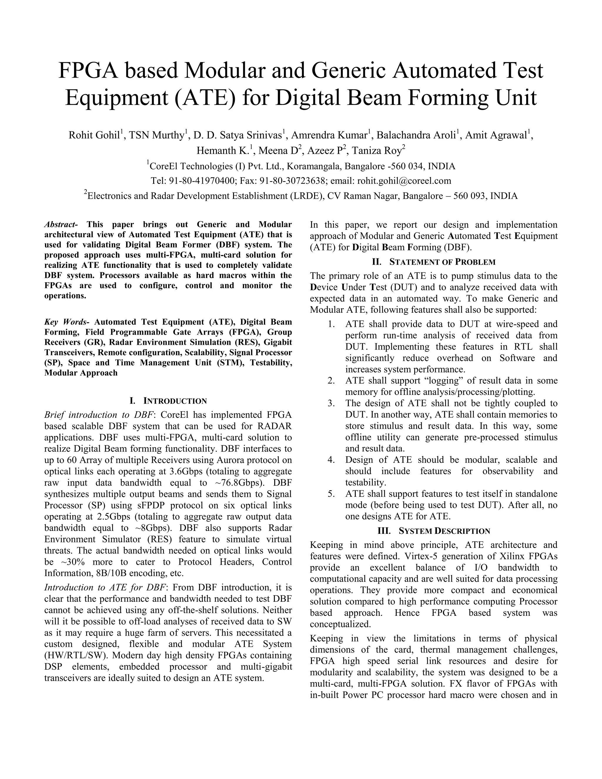
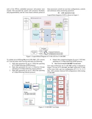
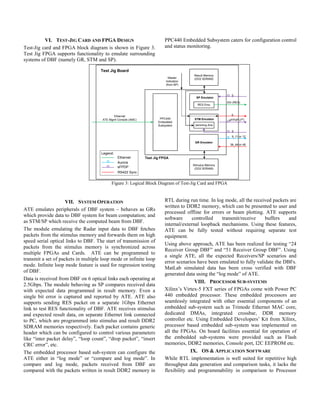
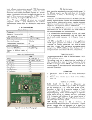

1) The document describes an FPGA-based modular and generic automated test equipment (ATE) designed for testing a digital beam forming (DBF) unit. 2) The ATE uses a multi-FPGA, multi-card solution to emulate radar components like receivers and transmitters and test the DBF system at full operating speeds. 3) The ATE architecture is modular and scalable, allowing it to test DBF systems with varying numbers of receivers through reconfiguration of the FPGA designs.