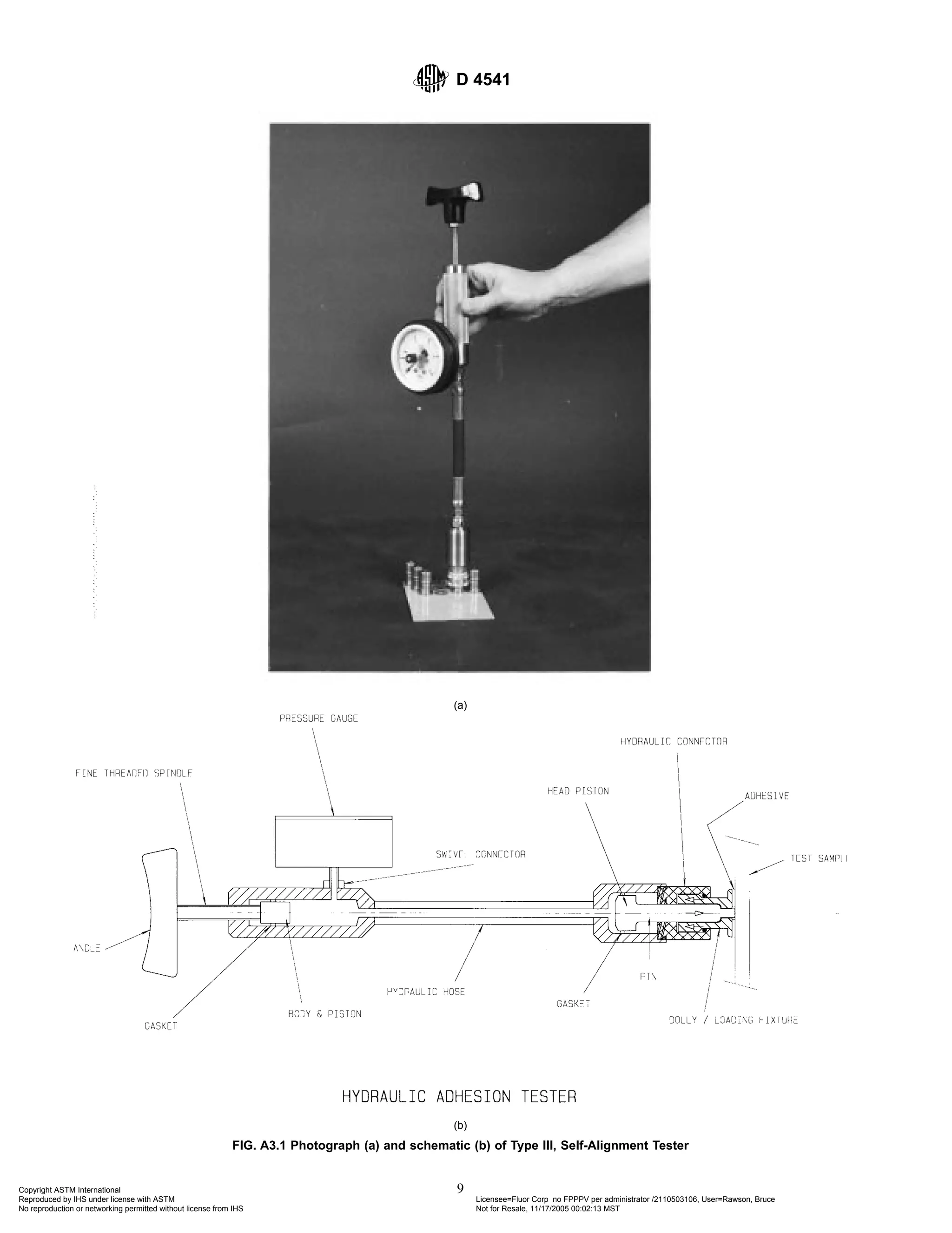
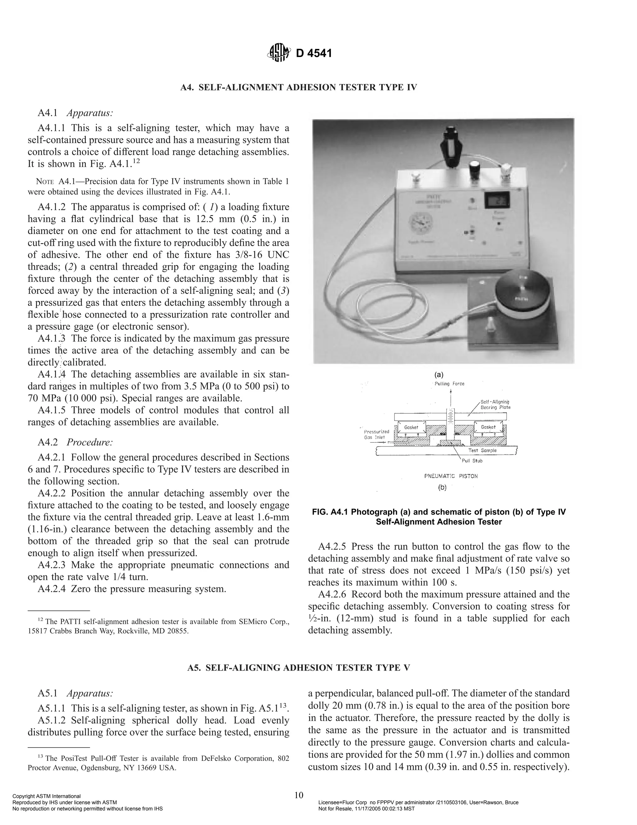
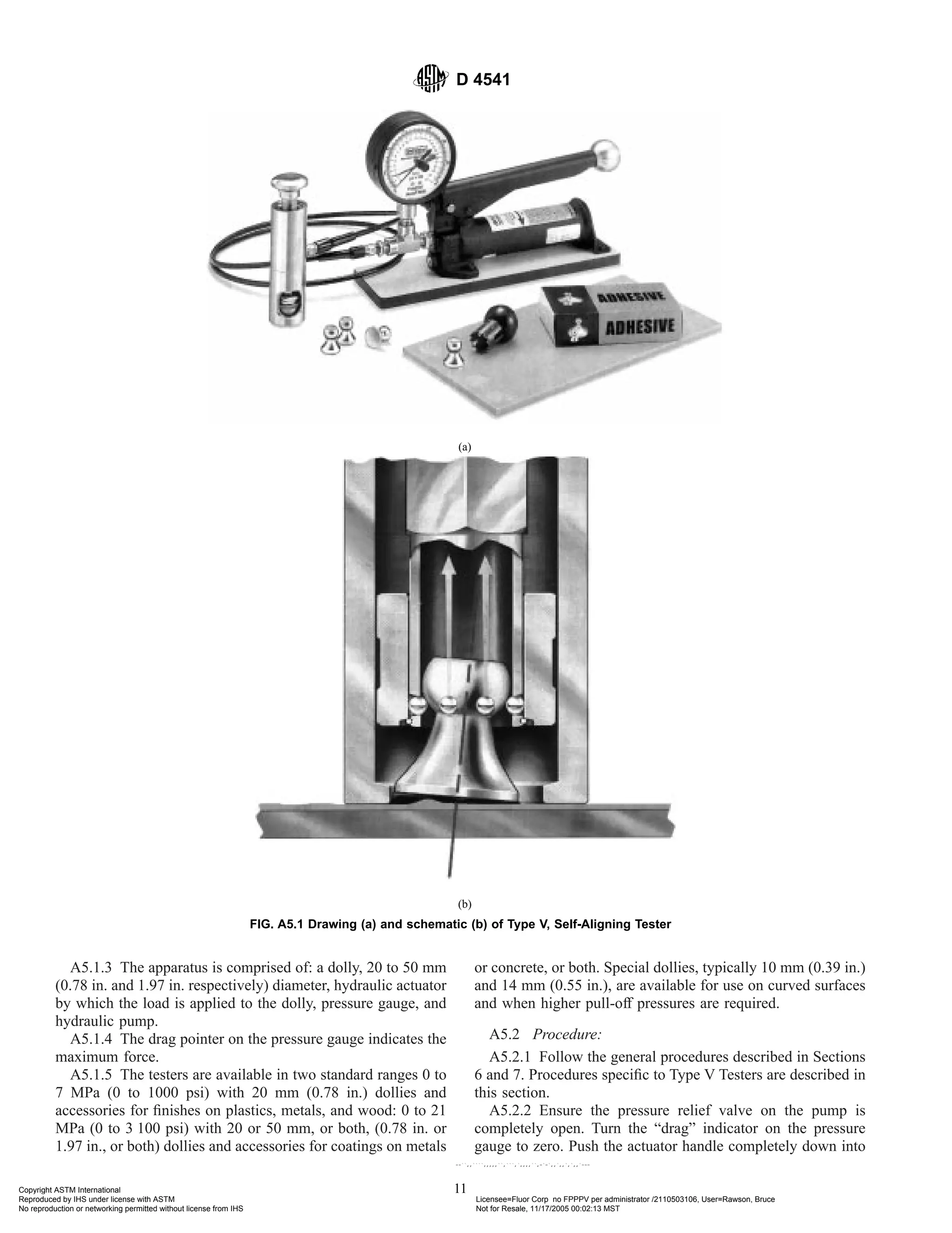
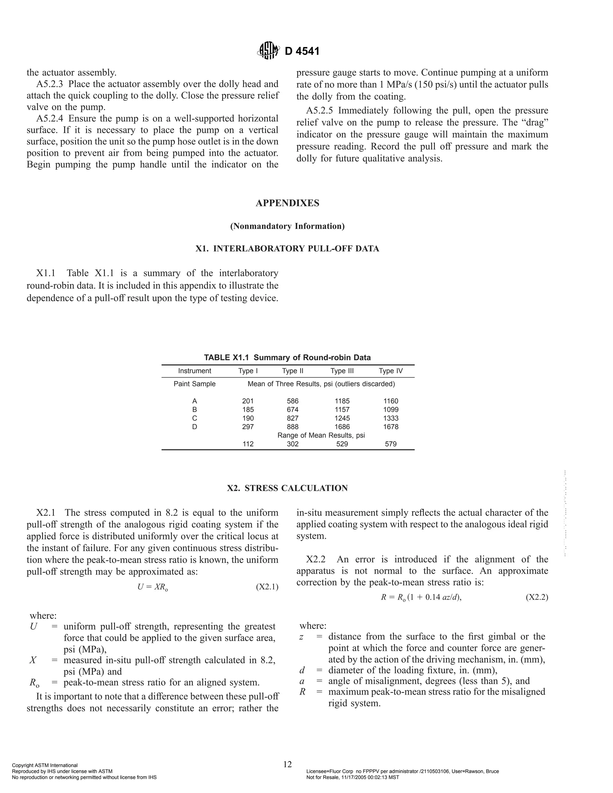
SlideShare a Scribd company logo
1 of 13
Download to read offline
Designation: D 4541 – 02
Standard Test Method for
Pull-Off Strength of Coatings Using Portable Adhesion
Testers1
This standard is issued under the fixed designation D 4541; the number immediately following the designation indicates the year of
original adoption or, in the case of revision, the year of last revision. A number in parentheses indicates the year of last reapproval. A
superscript epsilon (e) indicates an editorial change since the last revision or reapproval.
1. Scope
1.1 This test method covers a procedure for evaluating the
pull-off strength (commonly referred to as adhesion) of a
coating on rigid substrates such as metal, concrete or wood.
The test determines either the greatest perpendicular force (in
tension) that a surface area can bear before a plug of material
is detached, or whether the surface remains intact at a pre-
scribed force (pass/fail). Failure will occur along the weakest
plane within the system comprised of the test fixture, adhesive,
coating system, and substrate, and will be exposed by the
fracture surface. This test method maximizes tensile stress as
compared to the shear stress applied by other methods, such as
scratch or knife adhesion, and results may not be comparable.
1.2 Pull-off strength measurements depend upon both ma-
terial and instrumental parameters. Results obtained by each
test method may give different results. Results should only be
assessed for each test method and not be compared with other
instruments. There are five instrument types, identified as Test
Methods A-E. It is imperative to identify the test method used
when reporting results.
1.3 This test method uses a class of apparatus known as
portable pull-off adhesion testers.2
They are capable of apply-
ing a concentric load and counter load to a single surface so
that coatings can be tested even though only one side is
accessible. Measurements are limited by the strength of adhe-
sion bonds between the loading fixture and the specimen
surface or the cohesive strengths of the adhesive, coating
layers, and substrate.
1.4 This test can be destructive and spot repairs may be
necessary.
1.5 The values stated in MPa (inch-pound) units are to be
regarded as the standard. The values given in parentheses are
for information only.
1.6 This standard does not purport to address all of the
safety concerns, if any, associated with its use. It is the
responsibility of the user of this standard to establish appro-
priate safety and health practices and determine the applica-
bility of regulatory limitations prior to use.
2. Referenced Documents
2.1 ASTM Standards:
D 2651 Guide for Preparation of Metal Surfaces for Adhe-
sive Bonding3
D 3933 Guide for Preparation of Aluminum Surfaces for
Structural Adhesives Bonding (Phosphoric Acid Anodiz-
ing)3
D 3980 Practice for Interlaboratory Testing of Paint and
Related Materials4
2.2 ANSI Standard:
N512 Protective Coatings (Paints) for the Nuclear Industry5
2.3 ISO Standard:
4624 Paints and Varnish—Pull-Off Test for Adhesion5
3. Summary of Test Method
3.1 The general pull-off test is performed by securing a
loading fixture (dolly, stud) normal (perpendicular) to the
surface of the coating with an adhesive. After the adhesive is
cured, a testing apparatus is attached to the loading fixture and
aligned to apply tension normal to the test surface. The force
applied to the loading fixture is then gradually increased and
monitored until either a plug of material is detached, or a
specified value is reached. When a plug of material is detached,
the exposed surface represents the plane of limiting strength
within the system. The nature of the failure is qualified in
accordance with the percent of adhesive and cohesive failures,
and the actual interfaces and layers involved. The pull-off
strength is computed based on the maximum indicated load,
the instrument calibration data, and the original surface area
stressed. Pull-off strength results obtained using different
devices may be different because the results depend on
instrumental parameters (see Appendix X1).
4. Significance and Use
4.1 The pull-off strength of a coating is an important
performance property that has been used in specifications. This
1
This test method is under the jurisdiction of ASTM Committee D01 on Paint
and Related Coatings, Materials, and Applications and is the direct responsibility of
Subcommittee D01.46 on Industrial Protective Coatings.
Current edition approved Feb. 10, 2002. Published April 2002. Originally
published as D 4541 – 93. Last previous edition D 4541 – 95{1
.
2
The term adhesion tester may be somewhat of a misnomer, but its adoption by
two manufacturers and at least two patents indicates continued usage.
3
Annual Book of ASTM Standards, Vol 15.06.
4
Annual Book of ASTM Standards, Vol 06.01.
5
Available from American National Standards Institute, 11 W. 42nd St., 13th
Floor, New York, NY 10036.
1
Copyright © ASTM International, 100 Barr Harbor Drive, PO Box C700, West Conshohocken, PA 19428-2959, United States.
Copyright ASTM International
Reproduced by IHS under license with ASTM Licensee=Fluor Corp no FPPPV per administrator /2110503106, User=Rawson, Bruce
Not for Resale, 11/17/2005 00:02:13 MST
No reproduction or networking permitted without license from IHS
--``,,````,,,,,``,```,`,,,,``,-`-`,,`,,`,`,,`---
test method serves as a means for uniformly preparing and
testing coated surfaces, and evaluating and reporting the
results. This test method is applicable to any portable apparatus
meeting the basic requirements for determining the pull-off
strength of a coating.
4.2 Variations in results obtained using different devices or
different substrates with the same coating are possible (see
Appendix X1). Therefore, it is recommended that the type of
apparatus and the substrate be mutually agreed upon between
the interested parties.
4.3 The purchaser or specifier shall designate a specific test
method, that is, A, B, C, D or E, when calling out this standard.
5. Apparatus
5.1 Adhesion Tester, commercially available, or comparable
apparatus specific examples of which are listed in Annex
A1-Annex A5.
5.1.1 Loading Fixtures, having a flat surface on one end that
can be adhered to the coating and a means of attachment to the
tester on the other end.
5.1.2 Detaching Assembly (adhesion tester), having a cen-
tral grip for engaging the fixture.
5.1.3 Base, on the detaching assembly, or an annular bearing
ring if needed for uniformly pressing against the coating
surface around the fixture either directly, or by way of an
intermediate bearing ring. A means of aligning the base is
needed so that the resultant force is normal to the surface.
5.1.4 Means of moving the grip away from the base in as
smooth and continuous a manner as possible so that a torsion
free, co-axial (opposing pull of the grip and push of the base
along the same axis) force results between them.
5.1.5 Timer, or means of limiting the rate of stress to less
than 1 MPa/s (150 psi/s) so that the maximum stress is obtained
in less than about 100 s. A timer is the minimum equipment
when used by the operator along with the force indicator in
5.1.6.
NOTE 1—Obtaining the maximum stress in 100 s or less by keeping the
maximum rate of shear to less than 1 MPa/s (150 psi/s) is valid for the
levels of pull-off strength measured with these types of apparatuses.
5.1.6 Force Indicator and Calibration Information, for
determining the actual force delivered to the loading fixture.
5.2 Solvent, or other means for cleaning the loading fixture
surface. Finger prints, moisture, and oxides tend to be the
primary contaminants.
5.3 Fine Sandpaper, or other means of cleaning the coating
that will not alter its integrity by chemical or solvent attack. If
any light sanding is anticipated, choose only a very fine grade
abrasive (400 grit or finer) that will not introduce flaws or leave
a residue.
5.4 Adhesive, for securing the fixture to the coating that does
not affect the coating properties. Two component epoxies6
and
acrylics7
have been found to be the most versatile.
5.5 Magnetic or Mechanical Clamps, if needed, for holding
the fixture in place while the adhesive cures.
5.6 Cotton Swabs, or other means for removing excess
adhesive and defining the adhered area. Any method for
removing excess adhesive that damages the surface, such as
scoring (see 6.7), must generally be avoided since induced
surface flaws may cause premature failure of the coating.
5.7 Circular Hole Cutter (optional), to score through to the
substrate around the loading fixture.
6. Test Preparation
6.1 The method for selecting the coating sites to be prepared
for testing depends upon the objectives of the test and
agreements between the contracting parties. There are, how-
ever, a few physical restrictions imposed by the general method
and apparatus. The following requirements apply to all sites:
6.1.1 The selected test area must be a flat surface large
enough to accommodate the specified number of replicate tests.
The surface may have any orientation with reference to
gravitational pull. Each test site must be separated by at least
the distance needed to accommodate the detaching apparatus.
The size of a test site is essentially that of the secured loading
fixture. At least three replications are usually required in order
to statistically characterize the test area.
6.1.2 The selected test areas must also have enough perpen-
dicular and radial clearance to accommodate the apparatus, be
flat enough to permit alignment, and be rigid enough to support
the counter force. It should be noted that measurements close
to an edge may not be representative of the coating as a whole.
6.2 Since the rigidity of the substrate affects pull-off
strength results and is not a controllable test variable in field
measurements, some knowledge of the substrate thickness and
composition should be reported for subsequent analysis or
laboratory comparisons. For example, steel substrate of less
than 3.2 mm (1⁄8-in.) thickness usually reduce pull-off strength
results compared to 6.4 mm (1⁄4-in.) thick steel substrates.
6.3 Subject to the requirements of 6.1, select representative
test areas and clean the surfaces in a manner that will not affect
integrity of the coating or leave a residue. Surface abrasion
may introduce flaws and should generally be avoided. A fine
abrasive (see 5.3) should only be used if needed to remove
loose or weakly adhered surface contaminants.
6.4 Clean the loading fixture surface as indicated by the
apparatus manufacturer. Failures at the fixture-adhesive inter-
face can often be avoided by treating the fixture surfaces in
accordance with an appropriate ASTM standard practice for
preparing metal surfaces for adhesive bonding.
NOTE 2—Guides D 2651 and D 3933 are typical of well-proven meth-
ods for improving adhesive bond strengths to metal surfaces.
6
Araldite Adhesive, available from Ciba-Geigy Plastics, Duxford, Cambridge,
CB2 4QA, England, Hysol Epoxy Patch Kit 907, available from Hysol Div., The
Dexter Corp., Willow Pass Rd., Pittsburg, CA 94565, and Scotch Weld Adhesive
1838B/A, available from 3M, Adhesives, Coatings and Sealers Div., 3M Center, St.
Paul, MN 55144, have been found satisfactory for this purpose.
7
Versiloc 201 and 204 with accelerator, available from Lord Corp., Industrial
Adhesive Div., 2000 W. Grandview Blvd., P.O. Box 10038, Erie, PA 16514, have
been found satisfactory for this purpose.
D 4541
2
Copyright ASTM International
Reproduced by IHS under license with ASTM Licensee=Fluor Corp no FPPPV per administrator /2110503106, User=Rawson, Bruce
Not for Resale, 11/17/2005 00:02:13 MST
No reproduction or networking permitted without license from IHS
--``,,````,,,,,``,```,`,,,,``,-`-`,,`,,`,`,,`---
6.5 Prepare the adhesive in accordance with the adhesive
manufacturer’s recommendations. Apply the adhesive to the
fixture or the surface to be tested, or both, using a method
recommended by the adhesive manufacturer. Be certain to
apply the adhesive across the entire surface. Position fixture on
the surface to be tested. Carefully remove the excess adhesive
from around the fixture. (Warning—Movement, especially
twisting, can cause tiny bubbles to coalesce into large holidays
that constitute stress discontinuities during testing.)
NOTE 3—Adding about 1 percent of #5 glass beads to the adhesive
assists in even alignment of the test fixture to the surface.
6.6 Based on the adhesive manufacturer’s recommendations
and the anticipated environmental conditions, allow enough
time for the adhesive to set up and reach the recommended
cure. During the adhesive set and early cure stage, a constant
contact pressure should be maintained on the fixture. Magnetic
or mechanical clamping systems work well, but systems
relying on tack, such as masking tape, should be used with care
to ensure that they do not relax with time and allow air to
intrude between the fixture and the test area.
6.7 Scoring around the fixture violates the fundamental
in-situ test criterion that an unaltered coating be tested. If
scoring around the test surface is employed, extreme care is
required to prevent micro-cracking in the coating, since such
cracks may cause reduced adhesion values. Scored samples
constitute a different test, and this procedure should be clearly
reported with the results.
NOTE 4—It is common to score around the test fixture when performing
tests on cementitious substrates where the tensile strength of the substrate
is significantly lower than either the pull-off or cohesive strength of the
coating system.
6.8 Note the approximate temperature and relative humidity
during the time of test.
7. Test Procedure
7.1 Test Methods:
7.1.1 Test Method A — Fixed Alignment Adhesion Tester
Type I:
7.1.1.1 Operate the instrument in accordance with Annex
A1.
7.1.2 Test Method B — Fixed Alignment Adhesion Tester
Type II:
7.1.2.1 Operate the instrument in accordance with Annex
A2.
7.1.3 Test Method C — Self-Alignment Adhesion Tester Type
III:
7.1.3.1 Operate the instrument in accordance with Annex
A3.
7.1.4 Test Method D — Self-Alignment Adhesion Tester Type
IV:
7.1.4.1 Operate the instrument in accordance with Annex
A4.
7.1.5 Test Method E — Self-Alignment Adhesion Tester Type
V:
7.1.5.1 Operate the instrument in accordance with Annex
A5.
7.2 Select an adhesion-tester with a detaching assembly
having a force calibration spanning the range of expected
values along with its compatible loading fixture. Mid-range
measurements are usually the best, but read the manufacturer’s
operating instructions before proceeding.
7.3 If a bearing ring or comparable device (5.1.3) is to be
used, place it concentrically around the loading fixture on the
coating surface. If shims are required when a bearing ring is
employed, place them between the tester base and bearing ring
rather than on the coating surface.
7.4 Carefully connect the central grip of the detaching
assembly to the loading fixture without bumping, bending, or
otherwise prestressing the sample and connect the detaching
assembly to its control mechanism, if necessary. For nonhori-
zontal surfaces, support the detaching assembly so that its
weight does not contribute to the force exerted in the test.
7.5 Align the device according to the manufacturer’s in-
structions and set the force indicator to zero.
NOTE 5—Proper alignment is critical, see Appendix X2. If alignment is
required, use the procedure recommended by the manufacturer of the
adhesion tester and report the procedure used.
7.6 Increase the load to the fixture in as smooth and
continuous a manner as possible, at a rate of less than 1 MPa/s
(150 psi/s) so that failure occurs or the maximum stress is
reached in about 100 s or less (see Note 1).
7.7 Record the force attained at failure or the maximum
force applied.
7.8 If a plug of material is detached, label and store the
fixture for qualification of the failed surface in accordance with
8.3.
7.9 Report any departures from the procedure such as
possible misalignment, hesitations in the force application, etc.
8. Calculation and Interpretation of Results
8.1 If instructed by the manufacturer, use the instrument
calibration factors to convert the indicated force for each test
into the actual force applied.
8.2 Either use the calibration chart supplied by the manu-
facturer or compute the relative stress applied to each coating
sample as follows:
X 5 4F/pd 2
(1)
where:
X = greatest mean pull-off stress applied during a pass/fail
test, or the pull-off strength achieved at failure. Both
have units of MPa (psi).
F = actual force applied to the test surface as determined
in 8.1, and
d = equivalent diameter of the original surface area
stressed having units of inches (or millimetres). This
is usually equal to the diameter of the loading fixture.
8.3 For all tests to failure, estimate the percent of adhesive
and cohesive failures in accordance to their respective areas
and location within the test system comprised of coating and
adhesive layers. A convenient scheme that describes the total
test system is outlined in 8.3.1 through 8.3.3. (See ISO 4624.)
NOTE 6—A laboratory tensile testing machine is used in ISO 4624.
8.3.1 Describe the specimen as substrate A, upon which
D 4541
3
Copyright ASTM International
Reproduced by IHS under license with ASTM Licensee=Fluor Corp no FPPPV per administrator /2110503106, User=Rawson, Bruce
Not for Resale, 11/17/2005 00:02:13 MST
No reproduction or networking permitted without license from IHS
--``,,````,,,,,``,```,`,,,,``,-`-`,,`,,`,`,,`---
successive coating layers B, C, D, etc., have been applied,
including the adhesive, Y, that secures the fixture, Z, to the top
coat.
8.3.2 Designate cohesive failures by the layers within which
they occur as A, B, C, etc., and the percent of each.
8.3.3 Designate adhesive failures by the interfaces at which
they occur as A/B, B/C, C/D, etc., and the percent of each.
8.4 A result that is very different from most of the results
may be caused by a mistake in recording or calculating. If
either of these is not the cause, then examine the experimental
circumstances surrounding this run. If an irregular result can be
attributed to an experimental cause, drop this result from the
analysis. However, do not discard a result unless there are valid
nonstatistical reasons for doing so or unless the result is a
statistical outlier. Valid nonstatistical reasons for dropping
results include alignment of the apparatus that is not normal to
the surface, poor definition of the area stressed due to improper
application of the adhesive, poorly defined glue lines and
boundaries, holidays in the adhesive caused by voids or
inclusions, improperly prepared surfaces, and sliding or twist-
ing the fixture during the initial cure. Scratched or scored
samples may contain stress concentrations leading to prema-
ture fractures. Dixon’s test, as described in Practice D 3980,
may be used to detect outliers.
8.5 Disregard any test where glue failure represents more
than 50 % of the area. If a pass/fail criterium is being used and
a glue failure occurs at a pull-off strength greater than the
criterium, report the result as “pass with a pull-off strength
>{value obtained}...”
8.6 Further information relative to the interpretation of the
test results is given in Appendix X2.
9. Report
9.1 Report the following information:
9.1.1 Brief description of the general nature of the test, such
as, field or laboratory testing, generic type of coating, etc.
9.1.2 Temperature and relative humidity and any other
pertinent environmental conditions during the test period.
9.1.3 Description of the apparatus used, including: appara-
tus manufacturer and model number, loading fixture type and
dimensions, and bearing ring type and dimensions.
9.1.4 Description of the test system, if possible, by the
indexing scheme outlined in 8.3 including: product identity and
generic type for each coat and any other information supplied,
the substrate identity (thickness, type, orientation, etc.), and the
adhesive used.
9.1.5 Test results.
9.1.5.1 Date, test location, testing agent.
9.1.5.2 For pass/fail tests, stress applied along with the
result, for example, pass or fail and note the plane of any
failure (see 8.3 and ANSI N512).
9.1.5.3 For tests to failure, report all values computed in 8.2
along with the nature and location of the failures as specified in
8.3, or, if only the average strength is required, report the
average strength along with the statistics.
9.1.5.4 If corrections of the results have been made, or if
certain values have been omitted such as the lowest or highest
values or others, reasons for the adjustments and criteria used.
9.1.5.5 For any test where scoring was employed, indicate it
by placing a footnote superscript beside each data point
affected and a footnote to that effect at the bottom of each page
on which such data appears. Note any other deviations from the
procedure.
10. Precision and Bias 8
10.1 Precision—In an interlaboratory study of Test Methods
A-D, operators made measurements, generally in triplicate but
in a few cases in duplicate, on coated panels covering a
moderate range at the intermediate adhesion level using four
different types of instruments (see Annex A1-Annex A5 and
Appendix X1). The number of participating laboratories varied
with each instrument and in the case of one instrument with the
material. Only two laboratories had access to Type I instru-
ments but two operators in each made the triplicate tests.
During the statistical analysis of the results three individual
results and one set of triplicates obtained with Type II
instruments were rejected as outliers; one single test with Type
III instruments and three single results with Type I instruments
were rejected. The pooled intra- and inter-laboratory coeffi-
cients of variation were found to be those shown in Table 1.
Based on these coefficients the following criteria should be
used for judging, at the 95 % confidence level, the acceptability
of results:
10.1.1 Replicate Repeatability—Triplicate results obtained
by the same operator using instruments from the same category
should be considered suspect if they differ in percent relative
by more than the values given in Table 1.
NOTE 7—Difference in percent relative to two results, x1 and x2, is the
absolute value of
~x1 2 x 2!
~x1 1 x2!/2
3 100. (2)
10.1.2 Reproducibility—Two results, each the mean of trip-
licates, obtained by operators in different laboratories using
instruments of the same category should be considered suspect
if they differ in percent relative by more than the values given
in Table 1.
8
Supporting data are available from ASTM International Headquarters. Request
RR: D01-1094.
TABLE 1 Precision of Adhesion Pull-Off Measurements
Instrument
Coefficient of
Variation, v, %
Degrees of
Freedom
Maximum
Acceptable
Difference, %
Intralaboratory Instrument:
Type IV 8.5 48 29.0
Type I
Type II 12.2 129 41.0
Type III
Total 177
Interlaboratory Instrument:
Type IV 8.7 20 25.5
Type I
Type II 20.6 58 58.7
Type III
Total 78
D 4541
4
Copyright ASTM International
Reproduced by IHS under license with ASTM Licensee=Fluor Corp no FPPPV per administrator /2110503106, User=Rawson, Bruce
Not for Resale, 11/17/2005 00:02:13 MST
No reproduction or networking permitted without license from IHS
--``,,````,,,,,``,```,`,,,,``,-`-`,,`,,`,`,,`---
10.2 Bias—This test method has no bias statement since
there is no acceptable reference material suitable for determin-
ing the bias of this test method.
11. Keywords
11.1 adhesion; coatings; field; paint; portable; pull-off
strength; tensile test
ANNEXES
(Mandatory Information)
A1. FIXED-ALIGNMENT ADHESION TESTER, TYPE I
A1.1 Apparatus:
A1.1.1 A fixed-alignment portable tester as shown in Fig.
A1.19
NOTE A1.1—Precision data for Type I instruments described in Table 1
were obtained using the devices illustrated in Fig. A1.1.
A1.1.2 The tester is comprised of detachable aluminum
loading fixtures, 50 mm (1.97 in.) in diameter, screws with
spherical heads that are screwed into the center of a fixture, a
socket in the testing assembly that holds the head of the screw,
pressure gage, dynamometer, wheel and crank.
A1.1.3 The testers are available in four models, with maxi-
mum tensile forces of 5, 15, 25, and 50 kN (1125, 3375, 5625,
and 11 250 lb ) respectively. For a fixture having a 50 mm (1.97
in.) diameter, a 5 kN device corresponds to a range of 2.5 MPa
(0 to 360 psi).
A1.2 Procedure:
A1.2.1 Follow the general procedures described in Sections
6 and 7. Procedures specific to this instrument are described in
this section.
A1.2.2 Set the pointer on the zero mark by first pressing the
push-button located on the left of the indicator. While holding
the push-button, turn the little knob located on the upper part of
the indicator to set the pointer at zero. Set the zero after testing
by pressing the push-button.
A1.2.3 After fixing a loading fixture to a substrate, insert a
screw with a spherical head into the center of the fixture.
Position the testing equipment on the metal disc. Then by
means of the notched wheel, fix the head of the spherical screw
into the socket at the base of the equipment. For the first
mechanical approach, stop screwing down the wheel when the
pointer on the indicator shifts from the ZERO mark. Tests are
done by turning the crank. After each test, turn the crank in the
opposite direction until it stops.
9
The Dyna Z5 tester is available from PROCEQ SA, Riesbachstrasse 57,
CH-8034, Zurich, Switzerland.
D 4541
5
Copyright ASTM International
Reproduced by IHS under license with ASTM Licensee=Fluor Corp no FPPPV per administrator /2110503106, User=Rawson, Bruce
Not for Resale, 11/17/2005 00:02:13 MST
No reproduction or networking permitted without license from IHS
--``,,````,,,,,``,```,`,,,,``,-`-`,,`,,`,`,,`---
A2. FIXED-ALIGNMENT ADHESION TESTER TYPE II
A2.1 Apparatus:
A2.1.1 This is a fixed-alignment portable tester, as shown in
Fig. A2.1.10
NOTE A2.1—Precision data for Table 1 were obtained using the devices
illustrated in Fig. A2.1.
A2.1.2 The tester is comprised of detachable aluminum
loading fixtures having a flat conic base that is 20 mm (0.8 in.)
in diameter on one end for securing to the coating, and a
circular T-bolt head on the other end, a central grip for
engaging the loading fixture that is forced away from a tripod
base by the interaction of a handwheel (or nut), and a coaxial
bolt connected through a series of belleville washers, or springs
in later models, that acts as both a torsion relief and a spring
that displaces a dragging indicator with respect to a scale.
10
The Elcometer, Model 106, adhesion tester is available from Elcometer
Instruments, Ltd., Edge Lane, Droylston, Manchester M35 6UB, United Kingdom,
England.
(a)
(b)
FIG. A1.1 Photograph (a) and sketch (b) of Type I instruments
D 4541
6
Copyright ASTM International
Reproduced by IHS under license with ASTM Licensee=Fluor Corp no FPPPV per administrator /2110503106, User=Rawson, Bruce
Not for Resale, 11/17/2005 00:02:13 MST
No reproduction or networking permitted without license from IHS
--``,,````,,,,,``,```,`,,,,``,-`-`,,`,,`,`,,`---
A2.1.3 The force is indicated by measuring the maximum
spring displacement when loaded. Care should be taken to see
that substrate bending does not influence its final position or
the actual force delivered by the spring arrangement.
A2.1.4 The devices are available in four ranges: From 3.5,
7.0, 14, and 28 MPa ( 0 to 500, 0 to 1000, 0 to 2000, and 0 to
4000 psi ).
A2.2 Procedure:
A2.2.1 Center the bearing ring on the coating surface
concentric with the loading fixture. Turn the hand wheel or nut
of the tester counter-clockwise, lowering the grip so that it slips
under the head of the loading fixture.
A2.2.2 Align or shim the three instrument swivel pads of the
tripod base so that the instrument will pull perpendicularly to
the surface at the bearing ring. The annular ring can be used on
flexible substrates.
A2.2.3 Take up the slack between the various members and
slide the dragging (force) indicator located on the tester to zero.
A2.2.4 Firmly hold the instrument with one hand. Do not
allow the base to move or slide during the test. With the other
hand, turn the handwheel clockwise using as smooth and
constant motion as possible. Do not jerk or exceed a stress rate
of 150 psi/s (1 MPa/s) that is attained by allowing in excess of
7 s/7 MPa (7 s/1000 psi), stress. If the 14 or 28 MPa (2000 or
4000 psi ) models are used, the handwheel is replaced with a
nut requiring a wrench for tightening. The wrench must be used
in a plane parallel to the substrate so that the loading fixture
will not be removed by a shearing force or misalignment, thus
negating the results. The maximum stress must be reached
within about 100 s.
A2.2.5 The pulling force applied to the loading fixture is
increased to a maximum or until the system fails at its weakest
locus. Upon failure, the scale will rise slightly, while the
dragging indicator retains the apparent load. The apparatus
scale indicates an approximate stress directly in pounds per
square inch, but may be compared to a calibration curve.
A2.2.6 Record the highest value attained by reading along
the bottom of the dragging indicator.
(a)
(b)
FIG. A2.1 Photograph (a) and schematic (b) of Type II, Fixed
Alignment Pull-Off Tester
D 4541
7
Copyright ASTM International
Reproduced by IHS under license with ASTM Licensee=Fluor Corp no FPPPV per administrator /2110503106, User=Rawson, Bruce
Not for Resale, 11/17/2005 00:02:13 MST
No reproduction or networking permitted without license from IHS
--``,,````,,,,,``,```,`,,,,``,-`-`,,`,,`,`,,`---
A3. SELF-ALIGNING ADHESION TESTER TYPE III
A3.1 Apparatus:
A3.1.1 This is a self-aligning tester, as shown in Fig. A3.1.11
NOTE A3.1—Precision data for Type II instruments shown in Table 1
were obtained using the devices described in Fig. A3.1.
A3.1.2 Load is applied through the center of the dolly by a
hydraulic piston and pin. The diameter of the piston bore is
sized so that the area of the bore is equal to the net area of the
dolly. Therefore, the pressure reacted by the dolly is the same
as the pressure in the bore and is transmitted directly to a
pressure gage.
A3.1.3 The apparatus is comprised of: a dolly, 19 mm (0.75
in.) outside diameter, 3 mm (0.125 in.) inside diameter,
hydraulic piston and pin by which load is applied to the dolly,
hose, pressure gage, threaded plunger and handle.
A3.1.4 The force is indicated by the maximum hydraulic
pressure as displayed on the gage, since the effective areas of
the piston bore and the dolly are the same.
A3.1.5 The testers are available in three standard working
ranges: 0 to 10 MPa (0 to 1500 psi), 0 to 15 MPa (0 to 2250
psi), 0 to 20 MPa (0 to 3000 psi). Special dollies shaped to test
tubular sections are available.
A3.2 Procedure:
A3.2.1 Follow the general procedures described in Sections
6 and 7. Procedures specific to this instrument are described in
this section.
A3.2.2 Insert a decreased TFE-fluorocarbon plug into the
dolly until the tip protrudes from the surface of the dolly. When
applying adhesive to the dolly, avoid getting adhesive on the
plug. Remove plug after holding the dolly in place for 10 s.
A3.2.3 Ensure that the black needle of the tester is reading
zero. Connect a test dolly to the head and increase the pressure
by turning the handle clockwise until the pin protrudes from
the dolly. Decrease pressure to zero and remove the test dolly.
A3.2.4 Connect the head to the dolly to be tested, by pulling
back the snap-on ring, pushing the head and releasing the
snap-on ring. Ensure the tester is held normal to the surface to
be tested and that the hose is straight.
A3.2.5 Increase the pressure slowly by turning the handle
clockwise until either the maximum stress or failure is reached.
11
The Hate Mark VII adhesion tester is available from Hydraulic Adhesion Test
Equipment, Ltd., 629 Inlet Rd., North Palm Beach, FL 33408.
D 4541
8
Copyright ASTM International
Reproduced by IHS under license with ASTM Licensee=Fluor Corp no FPPPV per administrator /2110503106, User=Rawson, Bruce
Not for Resale, 11/17/2005 00:02:13 MST
No reproduction or networking permitted without license from IHS
--``,,````,,,,,``,```,`,,,,``,-`-`,,`,,`,`,,`---
(a)
(b)
FIG. A3.1 Photograph (a) and schematic (b) of Type III, Self-Alignment Tester
D 4541
9
Copyright ASTM International
Reproduced by IHS under license with ASTM Licensee=Fluor Corp no FPPPV per administrator /2110503106, User=Rawson, Bruce
Not for Resale, 11/17/2005 00:02:13 MST
No reproduction or networking permitted without license from IHS
--``,,````,,,,,``,```,`,,,,``,-`-`,,`,,`,`,,`---
A4. SELF-ALIGNMENT ADHESION TESTER TYPE IV
A4.1 Apparatus:
A4.1.1 This is a self-aligning tester, which may have a
self-contained pressure source and has a measuring system that
controls a choice of different load range detaching assemblies.
It is shown in Fig. A4.1.12
NOTE A4.1—Precision data for Type IV instruments shown in Table 1
were obtained using the devices illustrated in Fig. A4.1.
A4.1.2 The apparatus is comprised of: ( 1) a loading fixture
having a flat cylindrical base that is 12.5 mm (0.5 in.) in
diameter on one end for attachment to the test coating and a
cut-off ring used with the fixture to reproducibly define the area
of adhesive. The other end of the fixture has 3/8-16 UNC
threads; (2) a central threaded grip for engaging the loading
fixture through the center of the detaching assembly that is
forced away by the interaction of a self-aligning seal; and (3)
a pressurized gas that enters the detaching assembly through a
flexible hose connected to a pressurization rate controller and
a pressure gage (or electronic sensor).
A4.1.3 The force is indicated by the maximum gas pressure
times the active area of the detaching assembly and can be
directly calibrated.
A4.1.4 The detaching assemblies are available in six stan-
dard ranges in multiples of two from 3.5 MPa (0 to 500 psi) to
70 MPa (10 000 psi). Special ranges are available.
A4.1.5 Three models of control modules that control all
ranges of detaching assemblies are available.
A4.2 Procedure:
A4.2.1 Follow the general procedures described in Sections
6 and 7. Procedures specific to Type IV testers are described in
the following section.
A4.2.2 Position the annular detaching assembly over the
fixture attached to the coating to be tested, and loosely engage
the fixture via the central threaded grip. Leave at least 1.6-mm
(1.16-in.) clearance between the detaching assembly and the
bottom of the threaded grip so that the seal can protrude
enough to align itself when pressurized.
A4.2.3 Make the appropriate pneumatic connections and
open the rate valve 1/4 turn.
A4.2.4 Zero the pressure measuring system.
A4.2.5 Press the run button to control the gas flow to the
detaching assembly and make final adjustment of rate valve so
that rate of stress does not exceed 1 MPa/s (150 psi/s) yet
reaches its maximum within 100 s.
A4.2.6 Record both the maximum pressure attained and the
specific detaching assembly. Conversion to coating stress for
1⁄2-in. (12-mm) stud is found in a table supplied for each
detaching assembly.
A5. SELF-ALIGNING ADHESION TESTER TYPE V
A5.1 Apparatus:
A5.1.1 This is a self-aligning tester, as shown in Fig. A5.113
.
A5.1.2 Self-aligning spherical dolly head. Load evenly
distributes pulling force over the surface being tested, ensuring
a perpendicular, balanced pull-off. The diameter of the standard
dolly 20 mm (0.78 in.) is equal to the area of the position bore
in the actuator. Therefore, the pressure reacted by the dolly is
the same as the pressure in the actuator and is transmitted
directly to the pressure gauge. Conversion charts and calcula-
tions are provided for the 50 mm (1.97 in.) dollies and common
custom sizes 10 and 14 mm (0.39 in. and 0.55 in. respectively).
12
The PATTI self-alignment adhesion tester is available from SEMicro Corp.,
15817 Crabbs Branch Way, Rockville, MD 20855.
13
The PosiTest Pull-Off Tester is available from DeFelsko Corporation, 802
Proctor Avenue, Ogdensburg, NY 13669 USA.
(a)
FIG. A4.1 Photograph (a) and schematic of piston (b) of Type IV
Self-Alignment Adhesion Tester
D 4541
10
Copyright ASTM International
Reproduced by IHS under license with ASTM Licensee=Fluor Corp no FPPPV per administrator /2110503106, User=Rawson, Bruce
Not for Resale, 11/17/2005 00:02:13 MST
No reproduction or networking permitted without license from IHS
--``,,````,,,,,``,```,`,,,,``,-`-`,,`,,`,`,,`---
A5.1.3 The apparatus is comprised of: a dolly, 20 to 50 mm
(0.78 in. and 1.97 in. respectively) diameter, hydraulic actuator
by which the load is applied to the dolly, pressure gauge, and
hydraulic pump.
A5.1.4 The drag pointer on the pressure gauge indicates the
maximum force.
A5.1.5 The testers are available in two standard ranges 0 to
7 MPa (0 to 1000 psi) with 20 mm (0.78 in.) dollies and
accessories for finishes on plastics, metals, and wood: 0 to 21
MPa (0 to 3 100 psi) with 20 or 50 mm, or both, (0.78 in. or
1.97 in., or both) dollies and accessories for coatings on metals
or concrete, or both. Special dollies, typically 10 mm (0.39 in.)
and 14 mm (0.55 in.), are available for use on curved surfaces
and when higher pull-off pressures are required.
A5.2 Procedure:
A5.2.1 Follow the general procedures described in Sections
6 and 7. Procedures specific to Type V Testers are described in
this section.
A5.2.2 Ensure the pressure relief valve on the pump is
completely open. Turn the “drag” indicator on the pressure
gauge to zero. Push the actuator handle completely down into
(a)
(b)
FIG. A5.1 Drawing (a) and schematic (b) of Type V, Self-Aligning Tester
D 4541
11
Copyright ASTM International
Reproduced by IHS under license with ASTM Licensee=Fluor Corp no FPPPV per administrator /2110503106, User=Rawson, Bruce
Not for Resale, 11/17/2005 00:02:13 MST
No reproduction or networking permitted without license from IHS
--``,,````,,,,,``,```,`,,,,``,-`-`,,`,,`,`,,`---
the actuator assembly.
A5.2.3 Place the actuator assembly over the dolly head and
attach the quick coupling to the dolly. Close the pressure relief
valve on the pump.
A5.2.4 Ensure the pump is on a well-supported horizontal
surface. If it is necessary to place the pump on a vertical
surface, position the unit so the pump hose outlet is in the down
position to prevent air from being pumped into the actuator.
Begin pumping the pump handle until the indicator on the
pressure gauge starts to move. Continue pumping at a uniform
rate of no more than 1 MPa/s (150 psi/s) until the actuator pulls
the dolly from the coating.
A5.2.5 Immediately following the pull, open the pressure
relief valve on the pump to release the pressure. The “drag”
indicator on the pressure gauge will maintain the maximum
pressure reading. Record the pull off pressure and mark the
dolly for future qualitative analysis.
APPENDIXES
(Nonmandatory Information)
X1. INTERLABORATORY PULL-OFF DATA
X1.1 Table X1.1 is a summary of the interlaboratory
round-robin data. It is included in this appendix to illustrate the
dependence of a pull-off result upon the type of testing device.
X2. STRESS CALCULATION
X2.1 The stress computed in 8.2 is equal to the uniform
pull-off strength of the analogous rigid coating system if the
applied force is distributed uniformly over the critical locus at
the instant of failure. For any given continuous stress distribu-
tion where the peak-to-mean stress ratio is known, the uniform
pull-off strength may be approximated as:
U 5 XRo (X2.1)
where:
U = uniform pull-off strength, representing the greatest
force that could be applied to the given surface area,
psi (MPa),
X = measured in-situ pull-off strength calculated in 8.2,
psi (MPa) and
Ro = peak-to-mean stress ratio for an aligned system.
It is important to note that a difference between these pull-off
strengths does not necessarily constitute an error; rather the
in-situ measurement simply reflects the actual character of the
applied coating system with respect to the analogous ideal rigid
system.
X2.2 An error is introduced if the alignment of the
apparatus is not normal to the surface. An approximate
correction by the peak-to-mean stress ratio is:
R 5 Ro ~1 1 0.14 az/d!, (X2.2)
where:
z = distance from the surface to the first gimbal or the
point at which the force and counter force are gener-
ated by the action of the driving mechanism, in. (mm),
d = diameter of the loading fixture, in. (mm),
a = angle of misalignment, degrees (less than 5), and
R = maximum peak-to-mean stress ratio for the misaligned
rigid system.
TABLE X1.1 Summary of Round-robin Data
Instrument Type I Type II Type III Type IV
Paint Sample Mean of Three Results, psi (outliers discarded)
A 201 586 1185 1160
B 185 674 1157 1099
C 190 827 1245 1333
D 297 888 1686 1678
Range of Mean Results, psi
112 302 529 579
D 4541
12
Copyright ASTM International
Reproduced by IHS under license with ASTM Licensee=Fluor Corp no FPPPV per administrator /2110503106, User=Rawson, Bruce
Not for Resale, 11/17/2005 00:02:13 MST
No reproduction or networking permitted without license from IHS
--``,,````,,,,,``,```,`,,,,``,-`-`,,`,,`,`,,`---
ASTM International takes no position respecting the validity of any patent rights asserted in connection with any item mentioned
in this standard. Users of this standard are expressly advised that determination of the validity of any such patent rights, and the risk
of infringement of such rights, are entirely their own responsibility.
This standard is subject to revision at any time by the responsible technical committee and must be reviewed every five years and
if not revised, either reapproved or withdrawn. Your comments are invited either for revision of this standard or for additional standards
and should be addressed to ASTM International Headquarters. Your comments will receive careful consideration at a meeting of the
responsible technical committee, which you may attend. If you feel that your comments have not received a fair hearing you should
make your views known to the ASTM Committee on Standards, at the address shown below.
This standard is copyrighted by ASTM International, 100 Barr Harbor Drive, PO Box C700, West Conshohocken, PA 19428-2959,
United States. Individual reprints (single or multiple copies) of this standard may be obtained by contacting ASTM at the above
address or at 610-832-9585 (phone), 610-832-9555 (fax), or service@astm.org (e-mail); or through the ASTM website
(www.astm.org).
D 4541
13
Copyright ASTM International
Reproduced by IHS under license with ASTM Licensee=Fluor Corp no FPPPV per administrator /2110503106, User=Rawson, Bruce
Not for Resale, 11/17/2005 00:02:13 MST
No reproduction or networking permitted without license from IHS
--``,,````,,,,,``,```,`,,,,``,-`-`,,`,,`,`,,`---

More Related Content

What's hot

E164 97 ut contact examination of weldments.en.es
E164 97 ut contact examination of weldments.en.esE164 97 ut contact examination of weldments.en.es
E164 97 ut contact examination of weldments.en.esJulioCastellar1
 
Ut procedure general
Ut procedure generalUt procedure general
Ut procedure generalnaiduvs
 
METHOD AND ASSESSMENT FOR LOAD TEST.ppt
METHOD AND ASSESSMENT FOR LOAD TEST.pptMETHOD AND ASSESSMENT FOR LOAD TEST.ppt
METHOD AND ASSESSMENT FOR LOAD TEST.pptShaheedAzhar
 
Ultrasonic testing 1766001
Ultrasonic testing 1766001Ultrasonic testing 1766001
Ultrasonic testing 1766001Melwyn Mayers
 
Normas de ensayos de vialidad nacional 1 1
Normas de ensayos de vialidad nacional 1 1Normas de ensayos de vialidad nacional 1 1
Normas de ensayos de vialidad nacional 1 1jnicolers
 
Astm e 965 96 - traduzida espanhol
Astm e 965   96 - traduzida espanholAstm e 965   96 - traduzida espanhol
Astm e 965 96 - traduzida espanholDaniel Pereira
 
05 cap4 pavimentos de concreto asfáltico método aashto-93.doc
05 cap4 pavimentos de concreto asfáltico método aashto-93.doc05 cap4 pavimentos de concreto asfáltico método aashto-93.doc
05 cap4 pavimentos de concreto asfáltico método aashto-93.docAngelica Hidalgo
 
Level 3 assessment as per api 579 1 asme ffs-1 for pressure vessel general me...
Level 3 assessment as per api 579 1 asme ffs-1 for pressure vessel general me...Level 3 assessment as per api 579 1 asme ffs-1 for pressure vessel general me...
Level 3 assessment as per api 579 1 asme ffs-1 for pressure vessel general me...Kingston Rivington
 
API 510 INSPECCION DE RECIPIENTES PRESENTACION.pdf
API 510 INSPECCION DE RECIPIENTES  PRESENTACION.pdfAPI 510 INSPECCION DE RECIPIENTES  PRESENTACION.pdf
API 510 INSPECCION DE RECIPIENTES PRESENTACION.pdfluisrojas881941
 
Brittle coating and test
Brittle coating and testBrittle coating and test
Brittle coating and testDavalsab M.L
 
Peek mod properties datasheet tecapeek_pvx_ensinger
Peek mod  properties datasheet  tecapeek_pvx_ensingerPeek mod  properties datasheet  tecapeek_pvx_ensinger
Peek mod properties datasheet tecapeek_pvx_ensingermandalika3
 
OmniPC Flaw Sizing Demo
OmniPC Flaw Sizing DemoOmniPC Flaw Sizing Demo
OmniPC Flaw Sizing DemoOlympus IMS
 
Saes h-001 - 2016
Saes h-001 - 2016Saes h-001 - 2016
Saes h-001 - 2016Faisal k v
 
Diseño de pavimento flexibles
Diseño de pavimento flexiblesDiseño de pavimento flexibles
Diseño de pavimento flexibles2051986
 

What's hot (20)

E164 97 ut contact examination of weldments.en.es
E164 97 ut contact examination of weldments.en.esE164 97 ut contact examination of weldments.en.es
E164 97 ut contact examination of weldments.en.es
 
Material testing
Material testingMaterial testing
Material testing
 
Ut procedure general
Ut procedure generalUt procedure general
Ut procedure general
 
METHOD AND ASSESSMENT FOR LOAD TEST.ppt
METHOD AND ASSESSMENT FOR LOAD TEST.pptMETHOD AND ASSESSMENT FOR LOAD TEST.ppt
METHOD AND ASSESSMENT FOR LOAD TEST.ppt
 
Ultrasonic testing 1766001
Ultrasonic testing 1766001Ultrasonic testing 1766001
Ultrasonic testing 1766001
 
Normas de ensayos de vialidad nacional 1 1
Normas de ensayos de vialidad nacional 1 1Normas de ensayos de vialidad nacional 1 1
Normas de ensayos de vialidad nacional 1 1
 
Astm e 965 96 - traduzida espanhol
Astm e 965   96 - traduzida espanholAstm e 965   96 - traduzida espanhol
Astm e 965 96 - traduzida espanhol
 
05 cap4 pavimentos de concreto asfáltico método aashto-93.doc
05 cap4 pavimentos de concreto asfáltico método aashto-93.doc05 cap4 pavimentos de concreto asfáltico método aashto-93.doc
05 cap4 pavimentos de concreto asfáltico método aashto-93.doc
 
CatalogoIPAC_2019.pdf
CatalogoIPAC_2019.pdfCatalogoIPAC_2019.pdf
CatalogoIPAC_2019.pdf
 
Level 3 assessment as per api 579 1 asme ffs-1 for pressure vessel general me...
Level 3 assessment as per api 579 1 asme ffs-1 for pressure vessel general me...Level 3 assessment as per api 579 1 asme ffs-1 for pressure vessel general me...
Level 3 assessment as per api 579 1 asme ffs-1 for pressure vessel general me...
 
Ultrasonics aws
Ultrasonics awsUltrasonics aws
Ultrasonics aws
 
API 510 INSPECCION DE RECIPIENTES PRESENTACION.pdf
API 510 INSPECCION DE RECIPIENTES  PRESENTACION.pdfAPI 510 INSPECCION DE RECIPIENTES  PRESENTACION.pdf
API 510 INSPECCION DE RECIPIENTES PRESENTACION.pdf
 
Brittle coating and test
Brittle coating and testBrittle coating and test
Brittle coating and test
 
Peek mod properties datasheet tecapeek_pvx_ensinger
Peek mod  properties datasheet  tecapeek_pvx_ensingerPeek mod  properties datasheet  tecapeek_pvx_ensinger
Peek mod properties datasheet tecapeek_pvx_ensinger
 
OmniPC Flaw Sizing Demo
OmniPC Flaw Sizing DemoOmniPC Flaw Sizing Demo
OmniPC Flaw Sizing Demo
 
Saes h-001 - 2016
Saes h-001 - 2016Saes h-001 - 2016
Saes h-001 - 2016
 
Diseño de pavimento flexibles
Diseño de pavimento flexiblesDiseño de pavimento flexibles
Diseño de pavimento flexibles
 
Asme sec viii div 1 icb
Asme sec viii div 1 icbAsme sec viii div 1 icb
Asme sec viii div 1 icb
 
Presentation on SECVIII
Presentation on SECVIIIPresentation on SECVIII
Presentation on SECVIII
 
TPI - Example Report.
TPI - Example Report.TPI - Example Report.
TPI - Example Report.
 

Similar to Astm d4541 standard pull off test for coatings

D6641D6641M.39883 Compressive Properties of Polymer Matrix Composite.pdf
D6641D6641M.39883 Compressive Properties of Polymer Matrix Composite.pdfD6641D6641M.39883 Compressive Properties of Polymer Matrix Composite.pdf
D6641D6641M.39883 Compressive Properties of Polymer Matrix Composite.pdfmahmoodkhan77
 
Astm d 4767_95_triaxial_cu_cohesive_soils
Astm d 4767_95_triaxial_cu_cohesive_soilsAstm d 4767_95_triaxial_cu_cohesive_soils
Astm d 4767_95_triaxial_cu_cohesive_soilsnktivan
 
Standard Test Method for Tensile Properties of Plastics
Standard Test Method for Tensile Properties of PlasticsStandard Test Method for Tensile Properties of Plastics
Standard Test Method for Tensile Properties of PlasticsTuongBinhMinh1
 
B 504 90 r02 espesor recubrimientos metalicos
B 504   90 r02  espesor recubrimientos metalicosB 504   90 r02  espesor recubrimientos metalicos
B 504 90 r02 espesor recubrimientos metalicosLPELABORATORIO
 
Techniques For Measuring Adhesion Abrasion Durability Of Coatings Inks By Sco...
Techniques For Measuring Adhesion Abrasion Durability Of Coatings Inks By Sco...Techniques For Measuring Adhesion Abrasion Durability Of Coatings Inks By Sco...
Techniques For Measuring Adhesion Abrasion Durability Of Coatings Inks By Sco...SabreenGroup
 
D3039D3039M.11914 2.pdf
D3039D3039M.11914 2.pdfD3039D3039M.11914 2.pdf
D3039D3039M.11914 2.pdfmahmoodkhan77
 
E8E8M.31295 Standard Test Methods for Tension Testing of Metallic Materials.pdf
E8E8M.31295 Standard Test Methods for Tension Testing of Metallic Materials.pdfE8E8M.31295 Standard Test Methods for Tension Testing of Metallic Materials.pdf
E8E8M.31295 Standard Test Methods for Tension Testing of Metallic Materials.pdfmahmoodkhan77
 
E8E8M.4876 Tension Testing of Metallic Materials.pdf
E8E8M.4876 Tension Testing of Metallic Materials.pdfE8E8M.4876 Tension Testing of Metallic Materials.pdf
E8E8M.4876 Tension Testing of Metallic Materials.pdfmahmoodkhan77
 
D3039D3039M.11914.pdf
D3039D3039M.11914.pdfD3039D3039M.11914.pdf
D3039D3039M.11914.pdfmahmoodkhan77
 
E8E8M.3597 Tension Testing of Metallic Materials.pdf
E8E8M.3597 Tension Testing of Metallic Materials.pdfE8E8M.3597 Tension Testing of Metallic Materials.pdf
E8E8M.3597 Tension Testing of Metallic Materials.pdfmahmoodkhan77
 
D3410D3410M.27027 Compressive Properties of Polymer Matrix Composite.pdf
D3410D3410M.27027 Compressive Properties of Polymer Matrix Composite.pdfD3410D3410M.27027 Compressive Properties of Polymer Matrix Composite.pdf
D3410D3410M.27027 Compressive Properties of Polymer Matrix Composite.pdfmahmoodkhan77
 

Similar to Astm d4541 standard pull off test for coatings (20)

D1004.pdf
D1004.pdfD1004.pdf
D1004.pdf
 
D6641D6641M.39883 Compressive Properties of Polymer Matrix Composite.pdf
D6641D6641M.39883 Compressive Properties of Polymer Matrix Composite.pdfD6641D6641M.39883 Compressive Properties of Polymer Matrix Composite.pdf
D6641D6641M.39883 Compressive Properties of Polymer Matrix Composite.pdf
 
Astm d 4767_95_triaxial_cu_cohesive_soils
Astm d 4767_95_triaxial_cu_cohesive_soilsAstm d 4767_95_triaxial_cu_cohesive_soils
Astm d 4767_95_triaxial_cu_cohesive_soils
 
ASTM D2922.pdf
ASTM D2922.pdfASTM D2922.pdf
ASTM D2922.pdf
 
Astm d5162
Astm d5162Astm d5162
Astm d5162
 
Standard Test Method for Tensile Properties of Plastics
Standard Test Method for Tensile Properties of PlasticsStandard Test Method for Tensile Properties of Plastics
Standard Test Method for Tensile Properties of Plastics
 
B 504 90 r02 espesor recubrimientos metalicos
B 504   90 r02  espesor recubrimientos metalicosB 504   90 r02  espesor recubrimientos metalicos
B 504 90 r02 espesor recubrimientos metalicos
 
Acuan bulk density
Acuan bulk densityAcuan bulk density
Acuan bulk density
 
D638.pdf
D638.pdfD638.pdf
D638.pdf
 
Techniques For Measuring Adhesion Abrasion Durability Of Coatings Inks By Sco...
Techniques For Measuring Adhesion Abrasion Durability Of Coatings Inks By Sco...Techniques For Measuring Adhesion Abrasion Durability Of Coatings Inks By Sco...
Techniques For Measuring Adhesion Abrasion Durability Of Coatings Inks By Sco...
 
D3039D3039M.11914 2.pdf
D3039D3039M.11914 2.pdfD3039D3039M.11914 2.pdf
D3039D3039M.11914 2.pdf
 
ASTM E8-E8M
ASTM E8-E8MASTM E8-E8M
ASTM E8-E8M
 
E8E8M.31295 Standard Test Methods for Tension Testing of Metallic Materials.pdf
E8E8M.31295 Standard Test Methods for Tension Testing of Metallic Materials.pdfE8E8M.31295 Standard Test Methods for Tension Testing of Metallic Materials.pdf
E8E8M.31295 Standard Test Methods for Tension Testing of Metallic Materials.pdf
 
E8E8M.4876 Tension Testing of Metallic Materials.pdf
E8E8M.4876 Tension Testing of Metallic Materials.pdfE8E8M.4876 Tension Testing of Metallic Materials.pdf
E8E8M.4876 Tension Testing of Metallic Materials.pdf
 
D3039D3039M.11914.pdf
D3039D3039M.11914.pdfD3039D3039M.11914.pdf
D3039D3039M.11914.pdf
 
E8E8M.3597 Tension Testing of Metallic Materials.pdf
E8E8M.3597 Tension Testing of Metallic Materials.pdfE8E8M.3597 Tension Testing of Metallic Materials.pdf
E8E8M.3597 Tension Testing of Metallic Materials.pdf
 
C29 c29m.30172
C29 c29m.30172C29 c29m.30172
C29 c29m.30172
 
Astm d429-03
Astm d429-03Astm d429-03
Astm d429-03
 
D3410D3410M.27027 Compressive Properties of Polymer Matrix Composite.pdf
D3410D3410M.27027 Compressive Properties of Polymer Matrix Composite.pdfD3410D3410M.27027 Compressive Properties of Polymer Matrix Composite.pdf
D3410D3410M.27027 Compressive Properties of Polymer Matrix Composite.pdf
 
Sspc pa 2-2012
Sspc pa 2-2012Sspc pa 2-2012
Sspc pa 2-2012
 

Recently uploaded

Gfe Mayur Vihar Call Girls Service WhatsApp -> 9999965857 Available 24x7 ^ De...
Gfe Mayur Vihar Call Girls Service WhatsApp -> 9999965857 Available 24x7 ^ De...Gfe Mayur Vihar Call Girls Service WhatsApp -> 9999965857 Available 24x7 ^ De...
Gfe Mayur Vihar Call Girls Service WhatsApp -> 9999965857 Available 24x7 ^ De...srsj9000
 
(ANJALI) Dange Chowk Call Girls Just Call 7001035870 [ Cash on Delivery ] Pun...
(ANJALI) Dange Chowk Call Girls Just Call 7001035870 [ Cash on Delivery ] Pun...(ANJALI) Dange Chowk Call Girls Just Call 7001035870 [ Cash on Delivery ] Pun...
(ANJALI) Dange Chowk Call Girls Just Call 7001035870 [ Cash on Delivery ] Pun...ranjana rawat
 
main PPT.pptx of girls hostel security using rfid
main PPT.pptx of girls hostel security using rfidmain PPT.pptx of girls hostel security using rfid
main PPT.pptx of girls hostel security using rfidNikhilNagaraju
 
OSVC_Meta-Data based Simulation Automation to overcome Verification Challenge...
OSVC_Meta-Data based Simulation Automation to overcome Verification Challenge...OSVC_Meta-Data based Simulation Automation to overcome Verification Challenge...
OSVC_Meta-Data based Simulation Automation to overcome Verification Challenge...Soham Mondal
 
HARMONY IN THE NATURE AND EXISTENCE - Unit-IV
HARMONY IN THE NATURE AND EXISTENCE - Unit-IVHARMONY IN THE NATURE AND EXISTENCE - Unit-IV
HARMONY IN THE NATURE AND EXISTENCE - Unit-IVRajaP95
 
Microscopic Analysis of Ceramic Materials.pptx
Microscopic Analysis of Ceramic Materials.pptxMicroscopic Analysis of Ceramic Materials.pptx
Microscopic Analysis of Ceramic Materials.pptxpurnimasatapathy1234
 
MANUFACTURING PROCESS-II UNIT-2 LATHE MACHINE
MANUFACTURING PROCESS-II UNIT-2 LATHE MACHINEMANUFACTURING PROCESS-II UNIT-2 LATHE MACHINE
MANUFACTURING PROCESS-II UNIT-2 LATHE MACHINESIVASHANKAR N
 
Introduction and different types of Ethernet.pptx
Introduction and different types of Ethernet.pptxIntroduction and different types of Ethernet.pptx
Introduction and different types of Ethernet.pptxupamatechverse
 
Software Development Life Cycle By Team Orange (Dept. of Pharmacy)
Software Development Life Cycle By  Team Orange (Dept. of Pharmacy)Software Development Life Cycle By  Team Orange (Dept. of Pharmacy)
Software Development Life Cycle By Team Orange (Dept. of Pharmacy)Suman Mia
 
(SHREYA) Chakan Call Girls Just Call 7001035870 [ Cash on Delivery ] Pune Esc...
(SHREYA) Chakan Call Girls Just Call 7001035870 [ Cash on Delivery ] Pune Esc...(SHREYA) Chakan Call Girls Just Call 7001035870 [ Cash on Delivery ] Pune Esc...
(SHREYA) Chakan Call Girls Just Call 7001035870 [ Cash on Delivery ] Pune Esc...ranjana rawat
 
What are the advantages and disadvantages of membrane structures.pptx
What are the advantages and disadvantages of membrane structures.pptxWhat are the advantages and disadvantages of membrane structures.pptx
What are the advantages and disadvantages of membrane structures.pptxwendy cai
 
Call Girls Delhi {Jodhpur} 9711199012 high profile service
Call Girls Delhi {Jodhpur} 9711199012 high profile serviceCall Girls Delhi {Jodhpur} 9711199012 high profile service
Call Girls Delhi {Jodhpur} 9711199012 high profile servicerehmti665
 
College Call Girls Nashik Nehal 7001305949 Independent Escort Service Nashik
College Call Girls Nashik Nehal 7001305949 Independent Escort Service NashikCollege Call Girls Nashik Nehal 7001305949 Independent Escort Service Nashik
College Call Girls Nashik Nehal 7001305949 Independent Escort Service NashikCall Girls in Nagpur High Profile
 
MANUFACTURING PROCESS-II UNIT-5 NC MACHINE TOOLS
MANUFACTURING PROCESS-II UNIT-5 NC MACHINE TOOLSMANUFACTURING PROCESS-II UNIT-5 NC MACHINE TOOLS
MANUFACTURING PROCESS-II UNIT-5 NC MACHINE TOOLSSIVASHANKAR N
 
(PRIYA) Rajgurunagar Call Girls Just Call 7001035870 [ Cash on Delivery ] Pun...
(PRIYA) Rajgurunagar Call Girls Just Call 7001035870 [ Cash on Delivery ] Pun...(PRIYA) Rajgurunagar Call Girls Just Call 7001035870 [ Cash on Delivery ] Pun...
(PRIYA) Rajgurunagar Call Girls Just Call 7001035870 [ Cash on Delivery ] Pun...ranjana rawat
 
Coefficient of Thermal Expansion and their Importance.pptx
Coefficient of Thermal Expansion and their Importance.pptxCoefficient of Thermal Expansion and their Importance.pptx
Coefficient of Thermal Expansion and their Importance.pptxAsutosh Ranjan
 
Sheet Pile Wall Design and Construction: A Practical Guide for Civil Engineer...
Sheet Pile Wall Design and Construction: A Practical Guide for Civil Engineer...Sheet Pile Wall Design and Construction: A Practical Guide for Civil Engineer...
Sheet Pile Wall Design and Construction: A Practical Guide for Civil Engineer...Dr.Costas Sachpazis
 

Recently uploaded (20)

Call Us -/9953056974- Call Girls In Vikaspuri-/- Delhi NCR
Call Us -/9953056974- Call Girls In Vikaspuri-/- Delhi NCRCall Us -/9953056974- Call Girls In Vikaspuri-/- Delhi NCR
Call Us -/9953056974- Call Girls In Vikaspuri-/- Delhi NCR
 
Gfe Mayur Vihar Call Girls Service WhatsApp -> 9999965857 Available 24x7 ^ De...
Gfe Mayur Vihar Call Girls Service WhatsApp -> 9999965857 Available 24x7 ^ De...Gfe Mayur Vihar Call Girls Service WhatsApp -> 9999965857 Available 24x7 ^ De...
Gfe Mayur Vihar Call Girls Service WhatsApp -> 9999965857 Available 24x7 ^ De...
 
(ANJALI) Dange Chowk Call Girls Just Call 7001035870 [ Cash on Delivery ] Pun...
(ANJALI) Dange Chowk Call Girls Just Call 7001035870 [ Cash on Delivery ] Pun...(ANJALI) Dange Chowk Call Girls Just Call 7001035870 [ Cash on Delivery ] Pun...
(ANJALI) Dange Chowk Call Girls Just Call 7001035870 [ Cash on Delivery ] Pun...
 
main PPT.pptx of girls hostel security using rfid
main PPT.pptx of girls hostel security using rfidmain PPT.pptx of girls hostel security using rfid
main PPT.pptx of girls hostel security using rfid
 
OSVC_Meta-Data based Simulation Automation to overcome Verification Challenge...
OSVC_Meta-Data based Simulation Automation to overcome Verification Challenge...OSVC_Meta-Data based Simulation Automation to overcome Verification Challenge...
OSVC_Meta-Data based Simulation Automation to overcome Verification Challenge...
 
9953056974 Call Girls In South Ex, Escorts (Delhi) NCR.pdf
9953056974 Call Girls In South Ex, Escorts (Delhi) NCR.pdf9953056974 Call Girls In South Ex, Escorts (Delhi) NCR.pdf
9953056974 Call Girls In South Ex, Escorts (Delhi) NCR.pdf
 
HARMONY IN THE NATURE AND EXISTENCE - Unit-IV
HARMONY IN THE NATURE AND EXISTENCE - Unit-IVHARMONY IN THE NATURE AND EXISTENCE - Unit-IV
HARMONY IN THE NATURE AND EXISTENCE - Unit-IV
 
Microscopic Analysis of Ceramic Materials.pptx
Microscopic Analysis of Ceramic Materials.pptxMicroscopic Analysis of Ceramic Materials.pptx
Microscopic Analysis of Ceramic Materials.pptx
 
MANUFACTURING PROCESS-II UNIT-2 LATHE MACHINE
MANUFACTURING PROCESS-II UNIT-2 LATHE MACHINEMANUFACTURING PROCESS-II UNIT-2 LATHE MACHINE
MANUFACTURING PROCESS-II UNIT-2 LATHE MACHINE
 
Introduction and different types of Ethernet.pptx
Introduction and different types of Ethernet.pptxIntroduction and different types of Ethernet.pptx
Introduction and different types of Ethernet.pptx
 
Software Development Life Cycle By Team Orange (Dept. of Pharmacy)
Software Development Life Cycle By  Team Orange (Dept. of Pharmacy)Software Development Life Cycle By  Team Orange (Dept. of Pharmacy)
Software Development Life Cycle By Team Orange (Dept. of Pharmacy)
 
(SHREYA) Chakan Call Girls Just Call 7001035870 [ Cash on Delivery ] Pune Esc...
(SHREYA) Chakan Call Girls Just Call 7001035870 [ Cash on Delivery ] Pune Esc...(SHREYA) Chakan Call Girls Just Call 7001035870 [ Cash on Delivery ] Pune Esc...
(SHREYA) Chakan Call Girls Just Call 7001035870 [ Cash on Delivery ] Pune Esc...
 
Roadmap to Membership of RICS - Pathways and Routes
Roadmap to Membership of RICS - Pathways and RoutesRoadmap to Membership of RICS - Pathways and Routes
Roadmap to Membership of RICS - Pathways and Routes
 
What are the advantages and disadvantages of membrane structures.pptx
What are the advantages and disadvantages of membrane structures.pptxWhat are the advantages and disadvantages of membrane structures.pptx
What are the advantages and disadvantages of membrane structures.pptx
 
Call Girls Delhi {Jodhpur} 9711199012 high profile service
Call Girls Delhi {Jodhpur} 9711199012 high profile serviceCall Girls Delhi {Jodhpur} 9711199012 high profile service
Call Girls Delhi {Jodhpur} 9711199012 high profile service
 
College Call Girls Nashik Nehal 7001305949 Independent Escort Service Nashik
College Call Girls Nashik Nehal 7001305949 Independent Escort Service NashikCollege Call Girls Nashik Nehal 7001305949 Independent Escort Service Nashik
College Call Girls Nashik Nehal 7001305949 Independent Escort Service Nashik
 
MANUFACTURING PROCESS-II UNIT-5 NC MACHINE TOOLS
MANUFACTURING PROCESS-II UNIT-5 NC MACHINE TOOLSMANUFACTURING PROCESS-II UNIT-5 NC MACHINE TOOLS
MANUFACTURING PROCESS-II UNIT-5 NC MACHINE TOOLS
 
(PRIYA) Rajgurunagar Call Girls Just Call 7001035870 [ Cash on Delivery ] Pun...
(PRIYA) Rajgurunagar Call Girls Just Call 7001035870 [ Cash on Delivery ] Pun...(PRIYA) Rajgurunagar Call Girls Just Call 7001035870 [ Cash on Delivery ] Pun...
(PRIYA) Rajgurunagar Call Girls Just Call 7001035870 [ Cash on Delivery ] Pun...
 
Coefficient of Thermal Expansion and their Importance.pptx
Coefficient of Thermal Expansion and their Importance.pptxCoefficient of Thermal Expansion and their Importance.pptx
Coefficient of Thermal Expansion and their Importance.pptx
 
Sheet Pile Wall Design and Construction: A Practical Guide for Civil Engineer...
Sheet Pile Wall Design and Construction: A Practical Guide for Civil Engineer...Sheet Pile Wall Design and Construction: A Practical Guide for Civil Engineer...
Sheet Pile Wall Design and Construction: A Practical Guide for Civil Engineer...
 

Astm d4541 standard pull off test for coatings

  • 1. Designation: D 4541 – 02 Standard Test Method for Pull-Off Strength of Coatings Using Portable Adhesion Testers1 This standard is issued under the fixed designation D 4541; the number immediately following the designation indicates the year of original adoption or, in the case of revision, the year of last revision. A number in parentheses indicates the year of last reapproval. A superscript epsilon (e) indicates an editorial change since the last revision or reapproval. 1. Scope 1.1 This test method covers a procedure for evaluating the pull-off strength (commonly referred to as adhesion) of a coating on rigid substrates such as metal, concrete or wood. The test determines either the greatest perpendicular force (in tension) that a surface area can bear before a plug of material is detached, or whether the surface remains intact at a pre- scribed force (pass/fail). Failure will occur along the weakest plane within the system comprised of the test fixture, adhesive, coating system, and substrate, and will be exposed by the fracture surface. This test method maximizes tensile stress as compared to the shear stress applied by other methods, such as scratch or knife adhesion, and results may not be comparable. 1.2 Pull-off strength measurements depend upon both ma- terial and instrumental parameters. Results obtained by each test method may give different results. Results should only be assessed for each test method and not be compared with other instruments. There are five instrument types, identified as Test Methods A-E. It is imperative to identify the test method used when reporting results. 1.3 This test method uses a class of apparatus known as portable pull-off adhesion testers.2 They are capable of apply- ing a concentric load and counter load to a single surface so that coatings can be tested even though only one side is accessible. Measurements are limited by the strength of adhe- sion bonds between the loading fixture and the specimen surface or the cohesive strengths of the adhesive, coating layers, and substrate. 1.4 This test can be destructive and spot repairs may be necessary. 1.5 The values stated in MPa (inch-pound) units are to be regarded as the standard. The values given in parentheses are for information only. 1.6 This standard does not purport to address all of the safety concerns, if any, associated with its use. It is the responsibility of the user of this standard to establish appro- priate safety and health practices and determine the applica- bility of regulatory limitations prior to use. 2. Referenced Documents 2.1 ASTM Standards: D 2651 Guide for Preparation of Metal Surfaces for Adhe- sive Bonding3 D 3933 Guide for Preparation of Aluminum Surfaces for Structural Adhesives Bonding (Phosphoric Acid Anodiz- ing)3 D 3980 Practice for Interlaboratory Testing of Paint and Related Materials4 2.2 ANSI Standard: N512 Protective Coatings (Paints) for the Nuclear Industry5 2.3 ISO Standard: 4624 Paints and Varnish—Pull-Off Test for Adhesion5 3. Summary of Test Method 3.1 The general pull-off test is performed by securing a loading fixture (dolly, stud) normal (perpendicular) to the surface of the coating with an adhesive. After the adhesive is cured, a testing apparatus is attached to the loading fixture and aligned to apply tension normal to the test surface. The force applied to the loading fixture is then gradually increased and monitored until either a plug of material is detached, or a specified value is reached. When a plug of material is detached, the exposed surface represents the plane of limiting strength within the system. The nature of the failure is qualified in accordance with the percent of adhesive and cohesive failures, and the actual interfaces and layers involved. The pull-off strength is computed based on the maximum indicated load, the instrument calibration data, and the original surface area stressed. Pull-off strength results obtained using different devices may be different because the results depend on instrumental parameters (see Appendix X1). 4. Significance and Use 4.1 The pull-off strength of a coating is an important performance property that has been used in specifications. This 1 This test method is under the jurisdiction of ASTM Committee D01 on Paint and Related Coatings, Materials, and Applications and is the direct responsibility of Subcommittee D01.46 on Industrial Protective Coatings. Current edition approved Feb. 10, 2002. Published April 2002. Originally published as D 4541 – 93. Last previous edition D 4541 – 95{1 . 2 The term adhesion tester may be somewhat of a misnomer, but its adoption by two manufacturers and at least two patents indicates continued usage. 3 Annual Book of ASTM Standards, Vol 15.06. 4 Annual Book of ASTM Standards, Vol 06.01. 5 Available from American National Standards Institute, 11 W. 42nd St., 13th Floor, New York, NY 10036. 1 Copyright © ASTM International, 100 Barr Harbor Drive, PO Box C700, West Conshohocken, PA 19428-2959, United States. Copyright ASTM International Reproduced by IHS under license with ASTM Licensee=Fluor Corp no FPPPV per administrator /2110503106, User=Rawson, Bruce Not for Resale, 11/17/2005 00:02:13 MST No reproduction or networking permitted without license from IHS --``,,````,,,,,``,```,`,,,,``,-`-`,,`,,`,`,,`---
  • 2. test method serves as a means for uniformly preparing and testing coated surfaces, and evaluating and reporting the results. This test method is applicable to any portable apparatus meeting the basic requirements for determining the pull-off strength of a coating. 4.2 Variations in results obtained using different devices or different substrates with the same coating are possible (see Appendix X1). Therefore, it is recommended that the type of apparatus and the substrate be mutually agreed upon between the interested parties. 4.3 The purchaser or specifier shall designate a specific test method, that is, A, B, C, D or E, when calling out this standard. 5. Apparatus 5.1 Adhesion Tester, commercially available, or comparable apparatus specific examples of which are listed in Annex A1-Annex A5. 5.1.1 Loading Fixtures, having a flat surface on one end that can be adhered to the coating and a means of attachment to the tester on the other end. 5.1.2 Detaching Assembly (adhesion tester), having a cen- tral grip for engaging the fixture. 5.1.3 Base, on the detaching assembly, or an annular bearing ring if needed for uniformly pressing against the coating surface around the fixture either directly, or by way of an intermediate bearing ring. A means of aligning the base is needed so that the resultant force is normal to the surface. 5.1.4 Means of moving the grip away from the base in as smooth and continuous a manner as possible so that a torsion free, co-axial (opposing pull of the grip and push of the base along the same axis) force results between them. 5.1.5 Timer, or means of limiting the rate of stress to less than 1 MPa/s (150 psi/s) so that the maximum stress is obtained in less than about 100 s. A timer is the minimum equipment when used by the operator along with the force indicator in 5.1.6. NOTE 1—Obtaining the maximum stress in 100 s or less by keeping the maximum rate of shear to less than 1 MPa/s (150 psi/s) is valid for the levels of pull-off strength measured with these types of apparatuses. 5.1.6 Force Indicator and Calibration Information, for determining the actual force delivered to the loading fixture. 5.2 Solvent, or other means for cleaning the loading fixture surface. Finger prints, moisture, and oxides tend to be the primary contaminants. 5.3 Fine Sandpaper, or other means of cleaning the coating that will not alter its integrity by chemical or solvent attack. If any light sanding is anticipated, choose only a very fine grade abrasive (400 grit or finer) that will not introduce flaws or leave a residue. 5.4 Adhesive, for securing the fixture to the coating that does not affect the coating properties. Two component epoxies6 and acrylics7 have been found to be the most versatile. 5.5 Magnetic or Mechanical Clamps, if needed, for holding the fixture in place while the adhesive cures. 5.6 Cotton Swabs, or other means for removing excess adhesive and defining the adhered area. Any method for removing excess adhesive that damages the surface, such as scoring (see 6.7), must generally be avoided since induced surface flaws may cause premature failure of the coating. 5.7 Circular Hole Cutter (optional), to score through to the substrate around the loading fixture. 6. Test Preparation 6.1 The method for selecting the coating sites to be prepared for testing depends upon the objectives of the test and agreements between the contracting parties. There are, how- ever, a few physical restrictions imposed by the general method and apparatus. The following requirements apply to all sites: 6.1.1 The selected test area must be a flat surface large enough to accommodate the specified number of replicate tests. The surface may have any orientation with reference to gravitational pull. Each test site must be separated by at least the distance needed to accommodate the detaching apparatus. The size of a test site is essentially that of the secured loading fixture. At least three replications are usually required in order to statistically characterize the test area. 6.1.2 The selected test areas must also have enough perpen- dicular and radial clearance to accommodate the apparatus, be flat enough to permit alignment, and be rigid enough to support the counter force. It should be noted that measurements close to an edge may not be representative of the coating as a whole. 6.2 Since the rigidity of the substrate affects pull-off strength results and is not a controllable test variable in field measurements, some knowledge of the substrate thickness and composition should be reported for subsequent analysis or laboratory comparisons. For example, steel substrate of less than 3.2 mm (1⁄8-in.) thickness usually reduce pull-off strength results compared to 6.4 mm (1⁄4-in.) thick steel substrates. 6.3 Subject to the requirements of 6.1, select representative test areas and clean the surfaces in a manner that will not affect integrity of the coating or leave a residue. Surface abrasion may introduce flaws and should generally be avoided. A fine abrasive (see 5.3) should only be used if needed to remove loose or weakly adhered surface contaminants. 6.4 Clean the loading fixture surface as indicated by the apparatus manufacturer. Failures at the fixture-adhesive inter- face can often be avoided by treating the fixture surfaces in accordance with an appropriate ASTM standard practice for preparing metal surfaces for adhesive bonding. NOTE 2—Guides D 2651 and D 3933 are typical of well-proven meth- ods for improving adhesive bond strengths to metal surfaces. 6 Araldite Adhesive, available from Ciba-Geigy Plastics, Duxford, Cambridge, CB2 4QA, England, Hysol Epoxy Patch Kit 907, available from Hysol Div., The Dexter Corp., Willow Pass Rd., Pittsburg, CA 94565, and Scotch Weld Adhesive 1838B/A, available from 3M, Adhesives, Coatings and Sealers Div., 3M Center, St. Paul, MN 55144, have been found satisfactory for this purpose. 7 Versiloc 201 and 204 with accelerator, available from Lord Corp., Industrial Adhesive Div., 2000 W. Grandview Blvd., P.O. Box 10038, Erie, PA 16514, have been found satisfactory for this purpose. D 4541 2 Copyright ASTM International Reproduced by IHS under license with ASTM Licensee=Fluor Corp no FPPPV per administrator /2110503106, User=Rawson, Bruce Not for Resale, 11/17/2005 00:02:13 MST No reproduction or networking permitted without license from IHS --``,,````,,,,,``,```,`,,,,``,-`-`,,`,,`,`,,`---
  • 3. 6.5 Prepare the adhesive in accordance with the adhesive manufacturer’s recommendations. Apply the adhesive to the fixture or the surface to be tested, or both, using a method recommended by the adhesive manufacturer. Be certain to apply the adhesive across the entire surface. Position fixture on the surface to be tested. Carefully remove the excess adhesive from around the fixture. (Warning—Movement, especially twisting, can cause tiny bubbles to coalesce into large holidays that constitute stress discontinuities during testing.) NOTE 3—Adding about 1 percent of #5 glass beads to the adhesive assists in even alignment of the test fixture to the surface. 6.6 Based on the adhesive manufacturer’s recommendations and the anticipated environmental conditions, allow enough time for the adhesive to set up and reach the recommended cure. During the adhesive set and early cure stage, a constant contact pressure should be maintained on the fixture. Magnetic or mechanical clamping systems work well, but systems relying on tack, such as masking tape, should be used with care to ensure that they do not relax with time and allow air to intrude between the fixture and the test area. 6.7 Scoring around the fixture violates the fundamental in-situ test criterion that an unaltered coating be tested. If scoring around the test surface is employed, extreme care is required to prevent micro-cracking in the coating, since such cracks may cause reduced adhesion values. Scored samples constitute a different test, and this procedure should be clearly reported with the results. NOTE 4—It is common to score around the test fixture when performing tests on cementitious substrates where the tensile strength of the substrate is significantly lower than either the pull-off or cohesive strength of the coating system. 6.8 Note the approximate temperature and relative humidity during the time of test. 7. Test Procedure 7.1 Test Methods: 7.1.1 Test Method A — Fixed Alignment Adhesion Tester Type I: 7.1.1.1 Operate the instrument in accordance with Annex A1. 7.1.2 Test Method B — Fixed Alignment Adhesion Tester Type II: 7.1.2.1 Operate the instrument in accordance with Annex A2. 7.1.3 Test Method C — Self-Alignment Adhesion Tester Type III: 7.1.3.1 Operate the instrument in accordance with Annex A3. 7.1.4 Test Method D — Self-Alignment Adhesion Tester Type IV: 7.1.4.1 Operate the instrument in accordance with Annex A4. 7.1.5 Test Method E — Self-Alignment Adhesion Tester Type V: 7.1.5.1 Operate the instrument in accordance with Annex A5. 7.2 Select an adhesion-tester with a detaching assembly having a force calibration spanning the range of expected values along with its compatible loading fixture. Mid-range measurements are usually the best, but read the manufacturer’s operating instructions before proceeding. 7.3 If a bearing ring or comparable device (5.1.3) is to be used, place it concentrically around the loading fixture on the coating surface. If shims are required when a bearing ring is employed, place them between the tester base and bearing ring rather than on the coating surface. 7.4 Carefully connect the central grip of the detaching assembly to the loading fixture without bumping, bending, or otherwise prestressing the sample and connect the detaching assembly to its control mechanism, if necessary. For nonhori- zontal surfaces, support the detaching assembly so that its weight does not contribute to the force exerted in the test. 7.5 Align the device according to the manufacturer’s in- structions and set the force indicator to zero. NOTE 5—Proper alignment is critical, see Appendix X2. If alignment is required, use the procedure recommended by the manufacturer of the adhesion tester and report the procedure used. 7.6 Increase the load to the fixture in as smooth and continuous a manner as possible, at a rate of less than 1 MPa/s (150 psi/s) so that failure occurs or the maximum stress is reached in about 100 s or less (see Note 1). 7.7 Record the force attained at failure or the maximum force applied. 7.8 If a plug of material is detached, label and store the fixture for qualification of the failed surface in accordance with 8.3. 7.9 Report any departures from the procedure such as possible misalignment, hesitations in the force application, etc. 8. Calculation and Interpretation of Results 8.1 If instructed by the manufacturer, use the instrument calibration factors to convert the indicated force for each test into the actual force applied. 8.2 Either use the calibration chart supplied by the manu- facturer or compute the relative stress applied to each coating sample as follows: X 5 4F/pd 2 (1) where: X = greatest mean pull-off stress applied during a pass/fail test, or the pull-off strength achieved at failure. Both have units of MPa (psi). F = actual force applied to the test surface as determined in 8.1, and d = equivalent diameter of the original surface area stressed having units of inches (or millimetres). This is usually equal to the diameter of the loading fixture. 8.3 For all tests to failure, estimate the percent of adhesive and cohesive failures in accordance to their respective areas and location within the test system comprised of coating and adhesive layers. A convenient scheme that describes the total test system is outlined in 8.3.1 through 8.3.3. (See ISO 4624.) NOTE 6—A laboratory tensile testing machine is used in ISO 4624. 8.3.1 Describe the specimen as substrate A, upon which D 4541 3 Copyright ASTM International Reproduced by IHS under license with ASTM Licensee=Fluor Corp no FPPPV per administrator /2110503106, User=Rawson, Bruce Not for Resale, 11/17/2005 00:02:13 MST No reproduction or networking permitted without license from IHS --``,,````,,,,,``,```,`,,,,``,-`-`,,`,,`,`,,`---
  • 4. successive coating layers B, C, D, etc., have been applied, including the adhesive, Y, that secures the fixture, Z, to the top coat. 8.3.2 Designate cohesive failures by the layers within which they occur as A, B, C, etc., and the percent of each. 8.3.3 Designate adhesive failures by the interfaces at which they occur as A/B, B/C, C/D, etc., and the percent of each. 8.4 A result that is very different from most of the results may be caused by a mistake in recording or calculating. If either of these is not the cause, then examine the experimental circumstances surrounding this run. If an irregular result can be attributed to an experimental cause, drop this result from the analysis. However, do not discard a result unless there are valid nonstatistical reasons for doing so or unless the result is a statistical outlier. Valid nonstatistical reasons for dropping results include alignment of the apparatus that is not normal to the surface, poor definition of the area stressed due to improper application of the adhesive, poorly defined glue lines and boundaries, holidays in the adhesive caused by voids or inclusions, improperly prepared surfaces, and sliding or twist- ing the fixture during the initial cure. Scratched or scored samples may contain stress concentrations leading to prema- ture fractures. Dixon’s test, as described in Practice D 3980, may be used to detect outliers. 8.5 Disregard any test where glue failure represents more than 50 % of the area. If a pass/fail criterium is being used and a glue failure occurs at a pull-off strength greater than the criterium, report the result as “pass with a pull-off strength >{value obtained}...” 8.6 Further information relative to the interpretation of the test results is given in Appendix X2. 9. Report 9.1 Report the following information: 9.1.1 Brief description of the general nature of the test, such as, field or laboratory testing, generic type of coating, etc. 9.1.2 Temperature and relative humidity and any other pertinent environmental conditions during the test period. 9.1.3 Description of the apparatus used, including: appara- tus manufacturer and model number, loading fixture type and dimensions, and bearing ring type and dimensions. 9.1.4 Description of the test system, if possible, by the indexing scheme outlined in 8.3 including: product identity and generic type for each coat and any other information supplied, the substrate identity (thickness, type, orientation, etc.), and the adhesive used. 9.1.5 Test results. 9.1.5.1 Date, test location, testing agent. 9.1.5.2 For pass/fail tests, stress applied along with the result, for example, pass or fail and note the plane of any failure (see 8.3 and ANSI N512). 9.1.5.3 For tests to failure, report all values computed in 8.2 along with the nature and location of the failures as specified in 8.3, or, if only the average strength is required, report the average strength along with the statistics. 9.1.5.4 If corrections of the results have been made, or if certain values have been omitted such as the lowest or highest values or others, reasons for the adjustments and criteria used. 9.1.5.5 For any test where scoring was employed, indicate it by placing a footnote superscript beside each data point affected and a footnote to that effect at the bottom of each page on which such data appears. Note any other deviations from the procedure. 10. Precision and Bias 8 10.1 Precision—In an interlaboratory study of Test Methods A-D, operators made measurements, generally in triplicate but in a few cases in duplicate, on coated panels covering a moderate range at the intermediate adhesion level using four different types of instruments (see Annex A1-Annex A5 and Appendix X1). The number of participating laboratories varied with each instrument and in the case of one instrument with the material. Only two laboratories had access to Type I instru- ments but two operators in each made the triplicate tests. During the statistical analysis of the results three individual results and one set of triplicates obtained with Type II instruments were rejected as outliers; one single test with Type III instruments and three single results with Type I instruments were rejected. The pooled intra- and inter-laboratory coeffi- cients of variation were found to be those shown in Table 1. Based on these coefficients the following criteria should be used for judging, at the 95 % confidence level, the acceptability of results: 10.1.1 Replicate Repeatability—Triplicate results obtained by the same operator using instruments from the same category should be considered suspect if they differ in percent relative by more than the values given in Table 1. NOTE 7—Difference in percent relative to two results, x1 and x2, is the absolute value of ~x1 2 x 2! ~x1 1 x2!/2 3 100. (2) 10.1.2 Reproducibility—Two results, each the mean of trip- licates, obtained by operators in different laboratories using instruments of the same category should be considered suspect if they differ in percent relative by more than the values given in Table 1. 8 Supporting data are available from ASTM International Headquarters. Request RR: D01-1094. TABLE 1 Precision of Adhesion Pull-Off Measurements Instrument Coefficient of Variation, v, % Degrees of Freedom Maximum Acceptable Difference, % Intralaboratory Instrument: Type IV 8.5 48 29.0 Type I Type II 12.2 129 41.0 Type III Total 177 Interlaboratory Instrument: Type IV 8.7 20 25.5 Type I Type II 20.6 58 58.7 Type III Total 78 D 4541 4 Copyright ASTM International Reproduced by IHS under license with ASTM Licensee=Fluor Corp no FPPPV per administrator /2110503106, User=Rawson, Bruce Not for Resale, 11/17/2005 00:02:13 MST No reproduction or networking permitted without license from IHS --``,,````,,,,,``,```,`,,,,``,-`-`,,`,,`,`,,`---
  • 5. 10.2 Bias—This test method has no bias statement since there is no acceptable reference material suitable for determin- ing the bias of this test method. 11. Keywords 11.1 adhesion; coatings; field; paint; portable; pull-off strength; tensile test ANNEXES (Mandatory Information) A1. FIXED-ALIGNMENT ADHESION TESTER, TYPE I A1.1 Apparatus: A1.1.1 A fixed-alignment portable tester as shown in Fig. A1.19 NOTE A1.1—Precision data for Type I instruments described in Table 1 were obtained using the devices illustrated in Fig. A1.1. A1.1.2 The tester is comprised of detachable aluminum loading fixtures, 50 mm (1.97 in.) in diameter, screws with spherical heads that are screwed into the center of a fixture, a socket in the testing assembly that holds the head of the screw, pressure gage, dynamometer, wheel and crank. A1.1.3 The testers are available in four models, with maxi- mum tensile forces of 5, 15, 25, and 50 kN (1125, 3375, 5625, and 11 250 lb ) respectively. For a fixture having a 50 mm (1.97 in.) diameter, a 5 kN device corresponds to a range of 2.5 MPa (0 to 360 psi). A1.2 Procedure: A1.2.1 Follow the general procedures described in Sections 6 and 7. Procedures specific to this instrument are described in this section. A1.2.2 Set the pointer on the zero mark by first pressing the push-button located on the left of the indicator. While holding the push-button, turn the little knob located on the upper part of the indicator to set the pointer at zero. Set the zero after testing by pressing the push-button. A1.2.3 After fixing a loading fixture to a substrate, insert a screw with a spherical head into the center of the fixture. Position the testing equipment on the metal disc. Then by means of the notched wheel, fix the head of the spherical screw into the socket at the base of the equipment. For the first mechanical approach, stop screwing down the wheel when the pointer on the indicator shifts from the ZERO mark. Tests are done by turning the crank. After each test, turn the crank in the opposite direction until it stops. 9 The Dyna Z5 tester is available from PROCEQ SA, Riesbachstrasse 57, CH-8034, Zurich, Switzerland. D 4541 5 Copyright ASTM International Reproduced by IHS under license with ASTM Licensee=Fluor Corp no FPPPV per administrator /2110503106, User=Rawson, Bruce Not for Resale, 11/17/2005 00:02:13 MST No reproduction or networking permitted without license from IHS --``,,````,,,,,``,```,`,,,,``,-`-`,,`,,`,`,,`---
  • 6. A2. FIXED-ALIGNMENT ADHESION TESTER TYPE II A2.1 Apparatus: A2.1.1 This is a fixed-alignment portable tester, as shown in Fig. A2.1.10 NOTE A2.1—Precision data for Table 1 were obtained using the devices illustrated in Fig. A2.1. A2.1.2 The tester is comprised of detachable aluminum loading fixtures having a flat conic base that is 20 mm (0.8 in.) in diameter on one end for securing to the coating, and a circular T-bolt head on the other end, a central grip for engaging the loading fixture that is forced away from a tripod base by the interaction of a handwheel (or nut), and a coaxial bolt connected through a series of belleville washers, or springs in later models, that acts as both a torsion relief and a spring that displaces a dragging indicator with respect to a scale. 10 The Elcometer, Model 106, adhesion tester is available from Elcometer Instruments, Ltd., Edge Lane, Droylston, Manchester M35 6UB, United Kingdom, England. (a) (b) FIG. A1.1 Photograph (a) and sketch (b) of Type I instruments D 4541 6 Copyright ASTM International Reproduced by IHS under license with ASTM Licensee=Fluor Corp no FPPPV per administrator /2110503106, User=Rawson, Bruce Not for Resale, 11/17/2005 00:02:13 MST No reproduction or networking permitted without license from IHS --``,,````,,,,,``,```,`,,,,``,-`-`,,`,,`,`,,`---
  • 7. A2.1.3 The force is indicated by measuring the maximum spring displacement when loaded. Care should be taken to see that substrate bending does not influence its final position or the actual force delivered by the spring arrangement. A2.1.4 The devices are available in four ranges: From 3.5, 7.0, 14, and 28 MPa ( 0 to 500, 0 to 1000, 0 to 2000, and 0 to 4000 psi ). A2.2 Procedure: A2.2.1 Center the bearing ring on the coating surface concentric with the loading fixture. Turn the hand wheel or nut of the tester counter-clockwise, lowering the grip so that it slips under the head of the loading fixture. A2.2.2 Align or shim the three instrument swivel pads of the tripod base so that the instrument will pull perpendicularly to the surface at the bearing ring. The annular ring can be used on flexible substrates. A2.2.3 Take up the slack between the various members and slide the dragging (force) indicator located on the tester to zero. A2.2.4 Firmly hold the instrument with one hand. Do not allow the base to move or slide during the test. With the other hand, turn the handwheel clockwise using as smooth and constant motion as possible. Do not jerk or exceed a stress rate of 150 psi/s (1 MPa/s) that is attained by allowing in excess of 7 s/7 MPa (7 s/1000 psi), stress. If the 14 or 28 MPa (2000 or 4000 psi ) models are used, the handwheel is replaced with a nut requiring a wrench for tightening. The wrench must be used in a plane parallel to the substrate so that the loading fixture will not be removed by a shearing force or misalignment, thus negating the results. The maximum stress must be reached within about 100 s. A2.2.5 The pulling force applied to the loading fixture is increased to a maximum or until the system fails at its weakest locus. Upon failure, the scale will rise slightly, while the dragging indicator retains the apparent load. The apparatus scale indicates an approximate stress directly in pounds per square inch, but may be compared to a calibration curve. A2.2.6 Record the highest value attained by reading along the bottom of the dragging indicator. (a) (b) FIG. A2.1 Photograph (a) and schematic (b) of Type II, Fixed Alignment Pull-Off Tester D 4541 7 Copyright ASTM International Reproduced by IHS under license with ASTM Licensee=Fluor Corp no FPPPV per administrator /2110503106, User=Rawson, Bruce Not for Resale, 11/17/2005 00:02:13 MST No reproduction or networking permitted without license from IHS --``,,````,,,,,``,```,`,,,,``,-`-`,,`,,`,`,,`---
  • 8. A3. SELF-ALIGNING ADHESION TESTER TYPE III A3.1 Apparatus: A3.1.1 This is a self-aligning tester, as shown in Fig. A3.1.11 NOTE A3.1—Precision data for Type II instruments shown in Table 1 were obtained using the devices described in Fig. A3.1. A3.1.2 Load is applied through the center of the dolly by a hydraulic piston and pin. The diameter of the piston bore is sized so that the area of the bore is equal to the net area of the dolly. Therefore, the pressure reacted by the dolly is the same as the pressure in the bore and is transmitted directly to a pressure gage. A3.1.3 The apparatus is comprised of: a dolly, 19 mm (0.75 in.) outside diameter, 3 mm (0.125 in.) inside diameter, hydraulic piston and pin by which load is applied to the dolly, hose, pressure gage, threaded plunger and handle. A3.1.4 The force is indicated by the maximum hydraulic pressure as displayed on the gage, since the effective areas of the piston bore and the dolly are the same. A3.1.5 The testers are available in three standard working ranges: 0 to 10 MPa (0 to 1500 psi), 0 to 15 MPa (0 to 2250 psi), 0 to 20 MPa (0 to 3000 psi). Special dollies shaped to test tubular sections are available. A3.2 Procedure: A3.2.1 Follow the general procedures described in Sections 6 and 7. Procedures specific to this instrument are described in this section. A3.2.2 Insert a decreased TFE-fluorocarbon plug into the dolly until the tip protrudes from the surface of the dolly. When applying adhesive to the dolly, avoid getting adhesive on the plug. Remove plug after holding the dolly in place for 10 s. A3.2.3 Ensure that the black needle of the tester is reading zero. Connect a test dolly to the head and increase the pressure by turning the handle clockwise until the pin protrudes from the dolly. Decrease pressure to zero and remove the test dolly. A3.2.4 Connect the head to the dolly to be tested, by pulling back the snap-on ring, pushing the head and releasing the snap-on ring. Ensure the tester is held normal to the surface to be tested and that the hose is straight. A3.2.5 Increase the pressure slowly by turning the handle clockwise until either the maximum stress or failure is reached. 11 The Hate Mark VII adhesion tester is available from Hydraulic Adhesion Test Equipment, Ltd., 629 Inlet Rd., North Palm Beach, FL 33408. D 4541 8 Copyright ASTM International Reproduced by IHS under license with ASTM Licensee=Fluor Corp no FPPPV per administrator /2110503106, User=Rawson, Bruce Not for Resale, 11/17/2005 00:02:13 MST No reproduction or networking permitted without license from IHS --``,,````,,,,,``,```,`,,,,``,-`-`,,`,,`,`,,`---
  • 9. (a) (b) FIG. A3.1 Photograph (a) and schematic (b) of Type III, Self-Alignment Tester D 4541 9 Copyright ASTM International Reproduced by IHS under license with ASTM Licensee=Fluor Corp no FPPPV per administrator /2110503106, User=Rawson, Bruce Not for Resale, 11/17/2005 00:02:13 MST No reproduction or networking permitted without license from IHS --``,,````,,,,,``,```,`,,,,``,-`-`,,`,,`,`,,`---
  • 10. A4. SELF-ALIGNMENT ADHESION TESTER TYPE IV A4.1 Apparatus: A4.1.1 This is a self-aligning tester, which may have a self-contained pressure source and has a measuring system that controls a choice of different load range detaching assemblies. It is shown in Fig. A4.1.12 NOTE A4.1—Precision data for Type IV instruments shown in Table 1 were obtained using the devices illustrated in Fig. A4.1. A4.1.2 The apparatus is comprised of: ( 1) a loading fixture having a flat cylindrical base that is 12.5 mm (0.5 in.) in diameter on one end for attachment to the test coating and a cut-off ring used with the fixture to reproducibly define the area of adhesive. The other end of the fixture has 3/8-16 UNC threads; (2) a central threaded grip for engaging the loading fixture through the center of the detaching assembly that is forced away by the interaction of a self-aligning seal; and (3) a pressurized gas that enters the detaching assembly through a flexible hose connected to a pressurization rate controller and a pressure gage (or electronic sensor). A4.1.3 The force is indicated by the maximum gas pressure times the active area of the detaching assembly and can be directly calibrated. A4.1.4 The detaching assemblies are available in six stan- dard ranges in multiples of two from 3.5 MPa (0 to 500 psi) to 70 MPa (10 000 psi). Special ranges are available. A4.1.5 Three models of control modules that control all ranges of detaching assemblies are available. A4.2 Procedure: A4.2.1 Follow the general procedures described in Sections 6 and 7. Procedures specific to Type IV testers are described in the following section. A4.2.2 Position the annular detaching assembly over the fixture attached to the coating to be tested, and loosely engage the fixture via the central threaded grip. Leave at least 1.6-mm (1.16-in.) clearance between the detaching assembly and the bottom of the threaded grip so that the seal can protrude enough to align itself when pressurized. A4.2.3 Make the appropriate pneumatic connections and open the rate valve 1/4 turn. A4.2.4 Zero the pressure measuring system. A4.2.5 Press the run button to control the gas flow to the detaching assembly and make final adjustment of rate valve so that rate of stress does not exceed 1 MPa/s (150 psi/s) yet reaches its maximum within 100 s. A4.2.6 Record both the maximum pressure attained and the specific detaching assembly. Conversion to coating stress for 1⁄2-in. (12-mm) stud is found in a table supplied for each detaching assembly. A5. SELF-ALIGNING ADHESION TESTER TYPE V A5.1 Apparatus: A5.1.1 This is a self-aligning tester, as shown in Fig. A5.113 . A5.1.2 Self-aligning spherical dolly head. Load evenly distributes pulling force over the surface being tested, ensuring a perpendicular, balanced pull-off. The diameter of the standard dolly 20 mm (0.78 in.) is equal to the area of the position bore in the actuator. Therefore, the pressure reacted by the dolly is the same as the pressure in the actuator and is transmitted directly to the pressure gauge. Conversion charts and calcula- tions are provided for the 50 mm (1.97 in.) dollies and common custom sizes 10 and 14 mm (0.39 in. and 0.55 in. respectively). 12 The PATTI self-alignment adhesion tester is available from SEMicro Corp., 15817 Crabbs Branch Way, Rockville, MD 20855. 13 The PosiTest Pull-Off Tester is available from DeFelsko Corporation, 802 Proctor Avenue, Ogdensburg, NY 13669 USA. (a) FIG. A4.1 Photograph (a) and schematic of piston (b) of Type IV Self-Alignment Adhesion Tester D 4541 10 Copyright ASTM International Reproduced by IHS under license with ASTM Licensee=Fluor Corp no FPPPV per administrator /2110503106, User=Rawson, Bruce Not for Resale, 11/17/2005 00:02:13 MST No reproduction or networking permitted without license from IHS --``,,````,,,,,``,```,`,,,,``,-`-`,,`,,`,`,,`---
  • 11. A5.1.3 The apparatus is comprised of: a dolly, 20 to 50 mm (0.78 in. and 1.97 in. respectively) diameter, hydraulic actuator by which the load is applied to the dolly, pressure gauge, and hydraulic pump. A5.1.4 The drag pointer on the pressure gauge indicates the maximum force. A5.1.5 The testers are available in two standard ranges 0 to 7 MPa (0 to 1000 psi) with 20 mm (0.78 in.) dollies and accessories for finishes on plastics, metals, and wood: 0 to 21 MPa (0 to 3 100 psi) with 20 or 50 mm, or both, (0.78 in. or 1.97 in., or both) dollies and accessories for coatings on metals or concrete, or both. Special dollies, typically 10 mm (0.39 in.) and 14 mm (0.55 in.), are available for use on curved surfaces and when higher pull-off pressures are required. A5.2 Procedure: A5.2.1 Follow the general procedures described in Sections 6 and 7. Procedures specific to Type V Testers are described in this section. A5.2.2 Ensure the pressure relief valve on the pump is completely open. Turn the “drag” indicator on the pressure gauge to zero. Push the actuator handle completely down into (a) (b) FIG. A5.1 Drawing (a) and schematic (b) of Type V, Self-Aligning Tester D 4541 11 Copyright ASTM International Reproduced by IHS under license with ASTM Licensee=Fluor Corp no FPPPV per administrator /2110503106, User=Rawson, Bruce Not for Resale, 11/17/2005 00:02:13 MST No reproduction or networking permitted without license from IHS --``,,````,,,,,``,```,`,,,,``,-`-`,,`,,`,`,,`---
  • 12. the actuator assembly. A5.2.3 Place the actuator assembly over the dolly head and attach the quick coupling to the dolly. Close the pressure relief valve on the pump. A5.2.4 Ensure the pump is on a well-supported horizontal surface. If it is necessary to place the pump on a vertical surface, position the unit so the pump hose outlet is in the down position to prevent air from being pumped into the actuator. Begin pumping the pump handle until the indicator on the pressure gauge starts to move. Continue pumping at a uniform rate of no more than 1 MPa/s (150 psi/s) until the actuator pulls the dolly from the coating. A5.2.5 Immediately following the pull, open the pressure relief valve on the pump to release the pressure. The “drag” indicator on the pressure gauge will maintain the maximum pressure reading. Record the pull off pressure and mark the dolly for future qualitative analysis. APPENDIXES (Nonmandatory Information) X1. INTERLABORATORY PULL-OFF DATA X1.1 Table X1.1 is a summary of the interlaboratory round-robin data. It is included in this appendix to illustrate the dependence of a pull-off result upon the type of testing device. X2. STRESS CALCULATION X2.1 The stress computed in 8.2 is equal to the uniform pull-off strength of the analogous rigid coating system if the applied force is distributed uniformly over the critical locus at the instant of failure. For any given continuous stress distribu- tion where the peak-to-mean stress ratio is known, the uniform pull-off strength may be approximated as: U 5 XRo (X2.1) where: U = uniform pull-off strength, representing the greatest force that could be applied to the given surface area, psi (MPa), X = measured in-situ pull-off strength calculated in 8.2, psi (MPa) and Ro = peak-to-mean stress ratio for an aligned system. It is important to note that a difference between these pull-off strengths does not necessarily constitute an error; rather the in-situ measurement simply reflects the actual character of the applied coating system with respect to the analogous ideal rigid system. X2.2 An error is introduced if the alignment of the apparatus is not normal to the surface. An approximate correction by the peak-to-mean stress ratio is: R 5 Ro ~1 1 0.14 az/d!, (X2.2) where: z = distance from the surface to the first gimbal or the point at which the force and counter force are gener- ated by the action of the driving mechanism, in. (mm), d = diameter of the loading fixture, in. (mm), a = angle of misalignment, degrees (less than 5), and R = maximum peak-to-mean stress ratio for the misaligned rigid system. TABLE X1.1 Summary of Round-robin Data Instrument Type I Type II Type III Type IV Paint Sample Mean of Three Results, psi (outliers discarded) A 201 586 1185 1160 B 185 674 1157 1099 C 190 827 1245 1333 D 297 888 1686 1678 Range of Mean Results, psi 112 302 529 579 D 4541 12 Copyright ASTM International Reproduced by IHS under license with ASTM Licensee=Fluor Corp no FPPPV per administrator /2110503106, User=Rawson, Bruce Not for Resale, 11/17/2005 00:02:13 MST No reproduction or networking permitted without license from IHS --``,,````,,,,,``,```,`,,,,``,-`-`,,`,,`,`,,`---
  • 13. ASTM International takes no position respecting the validity of any patent rights asserted in connection with any item mentioned in this standard. Users of this standard are expressly advised that determination of the validity of any such patent rights, and the risk of infringement of such rights, are entirely their own responsibility. This standard is subject to revision at any time by the responsible technical committee and must be reviewed every five years and if not revised, either reapproved or withdrawn. Your comments are invited either for revision of this standard or for additional standards and should be addressed to ASTM International Headquarters. Your comments will receive careful consideration at a meeting of the responsible technical committee, which you may attend. If you feel that your comments have not received a fair hearing you should make your views known to the ASTM Committee on Standards, at the address shown below. This standard is copyrighted by ASTM International, 100 Barr Harbor Drive, PO Box C700, West Conshohocken, PA 19428-2959, United States. Individual reprints (single or multiple copies) of this standard may be obtained by contacting ASTM at the above address or at 610-832-9585 (phone), 610-832-9555 (fax), or service@astm.org (e-mail); or through the ASTM website (www.astm.org). D 4541 13 Copyright ASTM International Reproduced by IHS under license with ASTM Licensee=Fluor Corp no FPPPV per administrator /2110503106, User=Rawson, Bruce Not for Resale, 11/17/2005 00:02:13 MST No reproduction or networking permitted without license from IHS --``,,````,,,,,``,```,`,,,,``,-`-`,,`,,`,`,,`---