The document outlines the ASME Section V nondestructive examination (NDE) rules for pressure vessels, emphasizing the responsibilities of inspectors and the requirements for examination procedures. It details the scope, acceptance standards for various NDE methods, and emphasizes the importance of record keeping and equipment calibration. The document also highlights specific practices for radiographic examinations and image quality indicators (IQIs) necessary for ensuring compliance with the code.


![60
SE-797 Standard Practice for Measuring Thickness By
Manual Ultrasonic Pulse-Echo Contact Method
Scope
This practice provides guidelines for measuring the thickness of materials
using the contact pulse-echo method at temperatures not to exceed **
200°F (93°C).
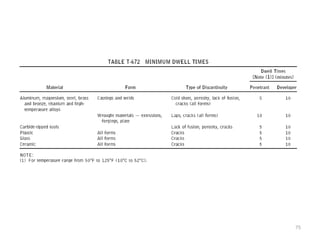
Thickness Adjustment SE-797 (9.5):
High-temperature materials, up to about 540°C [1000°F], can be measured
with specially designed instruments with high-temperature compensation,
search unit assemblies, and couplants. Normalization of apparent thickness
readings for elevated temperatures is required. A rule of thumb often used
is as follows: The apparent thickness reading obtained from steel walls
having elevated temperatures is high (too thick) by a factor of about 1 % per
55°C [100°F]. Thus, if the instrument was standardized on a piece of similar
material at 20°C [68°F], and if the reading was obtained with a surface
temperature of 460°C [860°F], the apparent reading should be reduced by 8
%.](https://image.slidesharecdn.com/asmesecvnew-241216082318-321ff989/85/ASME-Sec-V-New-NON-destructive-testing-60-320.jpg)