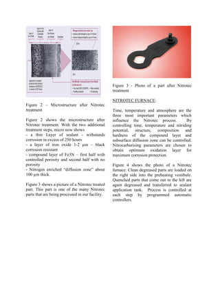
SlideShare a Scribd company logo
1 of 14
Download to read offline
SURFACE PROPERTIES ENHANCEMENT BY THE NITROTEC®
PROCESS
S.GOWRI1
, PRATAP GHORPADE1
and STEPHEN PLUMB2
ABSTRACT:
Nitrotec® belongs to the family of Surface Engineering processes. The name Nitrotec is
derived from the three important stages of the process namely NITRiding, Oxidising and
ProTECtion. This process is now available in India. This enhanced nitro-carburizing
treatment gives finished ferrous parts an exceptional corrosion and wear resistance,
bearing characteristics, high indentation, and scuffing, scoring and galling resistance and
a very smooth aesthetically pleasing black coloured surface. In addition to these
beneficial properties, some steels show great improvements in yield and tensile strength.
Nitrotec®
allows for treatment with far greater dimensional control compared to traditional
hardening practices where distortion occurs due to metallurgical phase changes and high
process temperatures. Nitrotec®
allows treatment of close tolerance precision parts
especially thin sections. Nitrotec®
is a worldwide trademark protected process and can
be applied to both steels and cast irons. This paper discusses the process, properties
and applications of Nitrotec®
.
1 Hightemp Furnaces Limited, Bangalore 2 Nitrotec, Birmingham, UK
INTRODUCTION
Nitrotec process is an enhancement of
nitrocarburising treatment. Nitrocarburising
is an old process and has been in existence
for over fifty years. In nitrocarburising, a thin
hard compound layer is formed on the
surface by the simultaneous diffusion of
nitrogen and carbon in steel. Primary
objective of nitrocarburing is to improve
wear properties. It is a low temperature
process and therefore is a low distortion
process. Initially this process was developed
with salt bath as the medium for enriching
the surface with nitrogen and carbon. Salt
baths used were based on alkali metal
cyanides and cyanates. This liquid
nitrocarburising goes by several commercial
names such as sulfinuz, tufftride, sursulf.
Because of the strict environmental laws and
high cost of disposing the toxic sludge, these
liquid carburizing processes based on
cyanides are slowly phasing out.
In early sixties, Lucas Industries in UK did
considerable amount of research in
developing a gaseous medium for
nitrocarburising. Their patented process used
a mixture of ammonia and endothermic gas
mixture. Over the next several years through
their pioneering work, they perfected the
gaseous nitrocarburising process and
technology.
Nitrocarburising has several advantages. The
process produces a very hard compound
layer with good wear resistance, galling and
scuffing resistance and bearing
characteristics. However, the treated parts
lacked good corrosion resistance and surface
finish, limiting their application only to wear
parts.
Lucas Industries extended their research
focus to develop a technique to improve
these two aspects of nitrocarburisng, namely,
corrosion and appearance. They came up
with a very simple and innovative but unique
technique to achieve this. They named the
new process “Nitrotec”. The name is based
on the three important processing
requirements namely; NITRiding, Oxidising
and proTECtion.
This world wide patented technology is now
licensed through TTI group of UK.
NITROTEC PROCESS
Sequence of events in Nitrotec process is,
therefore, Nitriding (nitrocarburising) the
parts, immediately subjecting them to flash
Oxidation before quenching followed by the
application of an additional protection
sealant. Oxidation gives enhanced corrosion
resistance and quenchant and sealant give
additional protection to the surface.
Nitrocarburising
Nitrocarburising is a thermochemical process
which produces a very shallow surface (case)
hardening. It is done at a lower temperature
of 530 ºC-720 ºC and for a short duration.
The process is further classified as ferritic
when the processing temperature is 530 ºC -
590 ºC and austenitic when the processing
temperature is 590 ºC -720 ºC.
Thermochemical enrichment of surface is
provided by a controlled gaseous mixture.
Ammonia is the main “active” gas in the
mixture for nitrogen enrichment. At the
operating temperature ammonia dissociates
as follows: 2NH3 → N2 (gas) + 3H2 (gas).
But this gaseous nitrogen does not contribute
to nitrogen enrichment. It is the catalytically
dissociated ammonia on the steel surface that
releases nascent nitrogen which contributes
to nitriding as follows: 2NH3 → N (in iron) +
3H2 (gas). So the nitriding potential inside
the furnace is controlled by the residual
ammonia residing in the furnace. Too much
or too little residual ammonia in the furnace
will affect the process and properties. Carbon
is enriched from carburizing agents such as
endothermic or methane or propane gas in
the “gaseous mixture”.
Compound Layer Formation
When residual ammonia in the furnace
comes into contact with steel surface nascent
nitrogen is released. This nascent nitrogen
diffuses into the steel and forms a solid
solution. Nitrogen readily diffused in ferrite
and austenite phase and the solubility
increases with increase in temperature.
Nitrogen continues to diffuse into steel until
the solubility limit is reached. At operating
conditions, nitrogen diffusion is observed to
a depth of 100 µm towards the core marked
by a clear “diffusion zone” also known as
“nitrogen enriched zone”.
When the limit is exceeded, if the gas
mixture is right, excess nitrogen starts
forming € Fe3N iron nitride ( iron carbo
nitride) non metallic compound referred as
“compound layer”. This compound layer is
very uniform and hard and can grow to a
depth of 5-40 µm. Hardness up to 1000VPN
can be easily achieved. Steels containing
alloying elements like Al, Mo, Cr, Mo can
attain even higher surface hardness.
Compound layer is micro porous at the
exterior surface and non porous in the
interior.
Picture (Fig 1) shows the microstructure of
the steel after nitrocarburising treatment.
Nitrocarburised surface consists of two
layers: first compound layer, (here about 20
µm thick) and beneath it is the nitrogen
enriched “diffusion zone”.
As indicated on the picture, compound layer
imparts wear and corrosion resistance and the
diffusion zone enhances yield, tensile and
fatigue strength. Enhancement in strength
properties are more pronounced in thin
sections.
Thus by proper control of nitriding potential
(residual ammonia) and temperature
(diffusion rates) and time (depth), hardness
of the compound layer and properties of
diffusion zone can be controlled. Success of
nitrocarburissing treatment depends on these
three important process controls.
Figure 1 – Microstructure after
Nitrocarburising
Oxidation
In regular nitrocarburising process, parts are
quenched or cooled after the nitriding
treatment.
In Nitrotec, parts are subjected to oxidation
step before quenching. In this post
nitrocarburising operation, parts are
deliberately exposed to oxygen atmosphere
for a controlled period of time and then
quenched. Oxidation step produces a thin
layer of oxide on the surface typically 1-2µm
in thickness. This oxide layer is mainly
magnetite Fe3O4 which is black in color and
corrosion resistant.
Oxidation step gives (a) additional protection
against corrosion (b) imparts an aesthetic
appealing black color to the surface (b) acts
as a carrier for subsequent organic sealant.
Quenching:
Quenching is done is a specially formulated
oil in water emulsion. Quenchant
temperature is carefully selected and
controlled to give an optimum cooling rate.
In Nitrotec cooling rate is optimized to (a) to
eliminate distortion (b) retain high temp
nitrogen enriched solid solution for
strengthening.
Sealant
After quenching work load is degreased and
immersed in specially formulated organic
sealant. Sealant covers the porous outer
layer. Sealant gives a very hard dry invisible
film on the surface.
Figure 2 – Microstructure after Nitrotec
treatment
Figure 2 shows the microstructure after
Nitrotec treatment. With the two additional
treatment steps, micro now shows
- a thin Layer of sealant - withstands
corrosion in excess of 250 hours
- a layer of iron oxide 1-2 µm – black
corrosion resistant
- compound layer of Fe3N – first half with
controlled porosity and second half with no
porosity
- Nitrogen enriched “diffusion zone” about
100 µm thick.
Figure 3 shows a picture of a Nitrotec treated
part. This part is one of the many Nitrotec
parts that are being processed in our facility.
Figure 3 - Photo of a part after Nitrotec
treatment
NITROTEC FURNACE:
Time, temperature and atmosphere are the
three most important parameters which
influence the Nitrotec process. By
controlling time, temperature and nitriding
potential, structure, composition and
hardness of the compound layer and
subsurface diffusion zone can be controlled.
Nitrocarburising parameters are chosen to
obtain optimum oxidation layer for
maximum corrosion protection.
Figure 4 shows the photo of a Nitrotec
furnace. Clean degreased parts are loaded on
the right side into the preheating vestibule.
Quenched parts that come out in the left are
again degreased and transferred to sealant
application tank. Process is controlled at
each step by programmed automatic
controllers.
Figure 4 – Photo of a Nitrotec treatment
furnace
BENEFITS OF NITROTEC TREATMENT
Property Improvements:
There are several properties that are
enhanced by the Nitrotec process. The hard
compound layer is resistant to wear, galling,
scoring, scuffing, has good bearing
characteristics, black oxide layer is resistant
to corrosion and nitrogen enriched diffusion
zone is strengthener. In addition to these
properties, Nitrotec process gives a
universally appealing black color to the parts.
Hardness:
Nitrotec process generates a hard nitride
layer 700-900 HV. The diffusion zone of
slightly lower hardness acts as a gradual
buffer between the hard surface and soft
core. Hardness developed is a
function of base material, alloying elements
and process temperature and time.
Figure shows a typical hardness profile after
Nitrotec treatment of different steels.
Figure 5 – Hardness profile of various steels
after Nitrotec treatment
Corrosion:
Nitrotec process improves significantly
corrosion resistance nitrocarburised parts.
Enhanced corrosion resistance is the major
benefit of Nitrotec treatment.
There are several methods to evaluate
corrosion of metals. Generally in surface
0
100
200
300
400
500
600
700
800
900
0.0 0.1 0.2 0.3 0.4 0.5
Depth from Surface mm.
Hardness(0.5kg)
817M40
709M40
605M36
080M40
Mild Steel
coating industries, accelerated corrosion
testing is carried out to check suitability
of the coating as a protective surface against
corrosion (b) to evaluate relative
(approximate) life of the coating with respect
to uncoated surface.
ASTM B117 is the common accelerated test
method which uses salt spray as the medium.
In this method parts to be tested are placed in
a closed chamber where salt solution is
sprayed continuously though nozzles. This
spray produces a severe corroding
atmosphere. Parts are periodically observed
for the start of visible corrosion product
(rust) on the surface of the part. More
resistant the coating is, more time for the
appearance of the corrosion products. This
method of testing is easy, simple and proven.
Figure 6 shows a comparison of corrosion
rates of EN 8 steel processed by different
treatments.
It is seen that nitrocarburised treatment by
itself does not give a good protection.
Incorporating oxidation and organic sealant
to nitrocarburised surfaces provide additional
corrosion resistance making it comparable to
that of hard chrome plating and medium
grade stainless steel.
In Nitrotec process, the layer formed is an
integral part of the surface. There is no
cracking or flaking. Whereas in chrome
plating the layer is deposited (built) on the
surface of the part and it has tendency to
flake off or blister or micro crack and expose
the bare metal surface to corrosion. Thus
Nitrotec is far superior to chrome plating and
is also much cheaper and cleaner than
chrome plating.
COMPARISONOFCROFDIFFERENTTREATMENTS
0
50
100
150
200
UNTREATED NITROCARBURISED HARDCHROME NITROTEC NITROTEC S 18/8STAINLESS
SURFACECOATINGPROCESS
CORROSIONRATE,µmPERYEAR
Figure 6 – Comparison of corrosion rate of
EN8 steel processed by different treatments
A slightly modified version of Nitrotec
process called “S” process gives corrosion
resistance comparable to that of 18/8
stainless steel.
Figures 7 (a) and (b) show the result of salt
spray test on chrome plated and Nitrotec
treated part.
Corrosion spots started appearing in chrome
plated parts very early. Picture shows the
progress of corrosion after 24 hours of
exposure.
Figure 7(a) – Chrome plated parts exposed to
salt spray – after 24 hours
In contrast to this, Nitrotec parts (Figure
7(b)) showed no sign of corrosion spots even
after 144 hours of exposure. Our regular
production parts are tested and certified for
minimum 240 hours of salt spray exposure.
Figure 7(b) – Nitrotec part exposed to salt
spray – after144 hours
Excellent Dimensional Stability:
Traditional hardening processes where parts
are heated to high temperature and quenched
to form high strength martensite are prone to
distortion, warping and cracking due to phase
transformations and accompanying volume
change. In high temperature hardening
process retaining the parts to the original
dimension is a challenging problem.
Because Nitrotec is a low temperature
process and carried out below the
transformation temperature distortion or
dimensional changes are minimal to nil.
Therefore finished parts can be treated and
used as is in applications. Even close
tolerance precision parts can be treated
without any problem.
Wear Resistance:
High surface hardness of the compound layer
gives Nitrotec parts superior wear resistance.
Iron nitride makes the parts more resistant to
galling, scuffing and scratching. Presence of
surface micro porosity also helps wear by
retaining lubricants.
Wear resistance of nitrotec steel is well
studied. Similar improvement in wear
resistance is also observed in Cast Iron.
Figure 8 shows % weight loss vs. time of SG
iron and Gary Iron test pins with and without
Nitrotec treatment. Wear testing was carried
out in dry wear conditions in a pin on disc
equipment. Several of 6 mm x 30 mm pins
(dia x length) were processed in Nitrotec
furnace at two different processing
conditions. Treated and untreated pins were
subjected to wear test under four different
loads and four different speeds. Wear was
measured as weight loss as a function of
time. As expected, wear increased with
increasing load and rpm. Only results of high
load (2.5kg) high speed (650 rpm) is given
here.
Matrix of SG iron was ferritic with a as cast
hardness of 160 BHN while that of GI was
pearlitic with a as cast hardness of 212 BHN.
After Nitrotec, surface hardness was found to
be 684-730 and 764-798 HV in SG and GI
respectively. This resulted in better wear as
seen from the figures.
Nitrotec is a viable option for increasing
surface properties of cast iron. Added
advantage is additional corrosion protection
from oxidation treatment.
% WEIGHT LOSS vs. TIME IN SG IRON
0
0.1
0.2
0.3
0.4
0.5
0.6
0.7
0.8
0 10 20 30 40 50 60 70
TIME IN MINUTES
%WEIGHTLOSS
NITROTEC 1 NITROTEC 2 AS CAST
% WEIGHT LOSS vs. TIME - GRAY IRON
0
0.1
0.2
0.3
0.4
0.5
0.6
0.7
0.8
0 10 20 30 40 50 60 70
TIME IN MINUTES
%WEIGHTLOSS
NITROTEC 1 NITROTEC 2 AS CAST
Figure 8 – % weight loss as a function of
time – load = 2.5 kg at 600 rpm
Yield Strength and Fatigue Strength:
Strengthening effect of nitrogen in the
diffusion zone gives nitrotec parts higher
yield, tensile and fatigue strengths. Fatigue
strength has been reported to increase four
times.
Figure 9 gives the yield strength of treated
and untreated unalloyed low carbon steel. It
is seen from the figure that yield strength
increases as section thickness decreases. This
increase is more than three times in thin
sections. That is for the same yield (or
tensile) strength, thickness of the original
part can be reduced by opting for nitrotec
treatments. By redesigning the components,
parts can be made thinner and less costly.
MATERIAL THICKNESS (mm)
0
100
200
300
400
500
600
700
YIELDSTRENGTH(M.p.a.)
Strength profiles of low carbon, non-alloy steel
after Optimised Nitrotec treatments.
Untreated
Nitrotec
Treated
0.5 1.0 1.5 3.0
Figure 9 – Yield strength increase after
Nitrotec treatment
Lucas first exploited this increase in yield
strength in changing the wind screen wiper
linkage part into a lower thickness part and
thereby obtaining 66% cost savings.
Similar property increase is seen in tubular
products. Figure 9 gives compression and
bending strength of 1.6mm treated and
untreated mild steel tube. Our studies have
shown that bending and compression results
of 1.6 mm untreated tube can be matched by
1.2 mm Nitrotec treated tube. This when
applied to one of the commercial two
wheeler part translated to a weight savings of
30%. A quick comparison of processing cost
(Nitrotec vs. chromium plating) translated to
an additional savings of 40%. Overall cost of
the part was reduced by 80 rupees per piece.
Figure 10 – Compression and bending
strength of Nitrotec treated (blue) and
untreated (black) MS tubes
Aesthetic Finish:
Nitrotec treatment gives an aesthetically
pleasing black appearance to parts.
Surface Finish:
With Nitrotec treatment initial good surface
finish can be retained.
Surface finish can be further improved by
Nitrotec S process. S process is another
enhancement to Nitrotec process where the
Nitrotec surface is polished to smooth finish
Bending Strength Comparisons, (1.6mm)
0
200
400
600
800
1000
1200
1400
1600
1800
2000
0 5 10 15 20 25 30
Displacement, (mm)
KgForce
Crush Strength Comparisons, (1.6mm)
0
100
200
300
400
500
600
700
800
900
1000
0 1 2 3 4 5 6 7 8 9
Displacement, (mm)
KgForce
and reoxidised to get an extremely smooth
shiny surface (low Ra of < 0.15). By S
process surface finish rivaling that of chrome
plating can be achieved.
Figure 11 –– surface finish improvement
With Nitrotec S process
APPLICATIONS OF NITROTEC:
Nitrotec parts are widely used by automobile
manufacturers, hydraulics and actuation
system providers, machinery builders and
producers of office supplies and consumer
goods.
CLUTCH LEVER
Material: - Low carbon Steel
This is a Clutch Lever used on a 4 x 4
vehicle, the specified surface protection
being a phosphate coating. Failure in service
occurred due to wear in the pressed dome of
the lever, this was caused by high pressure
metal to metal contact with the clutch
operating mechanism. Nitrotec treatment
gave increased strength together with the
required wear resistance in the dome and
eliminated the need for phosphate coating.
SEAT SLIDERS
This was a collaborative exercise between
Lucas and Rockwell to produce strength
properties by the required in seat slider
mechanisms fitted to an executive Renault
car. These components are normally
manufactured from low carbon steel and
painted. During final assembly, a quantity of
grease is applied to the channel and this
created problems when contacted by driver
or passenger. The hardened steel ball running
between the inner and outer slide during
transverse can cause indentation in the track.
Any indentations in the track affected the
smooth running of the seat adjustment. Also,
in this application, the seat slider was used as
an anchorage point for the safety belt. The
dimensional control of the profile of the slide
was critical to ensure the smooth running of
the roller track.
Several surface hardening techniques were
tried, but all of them produced unacceptable
levels of distortion and still required a
finishing operation. Nitrotec process
parameters were developed to produce a
specific hardness profile in the substrate
layer, together with the required wear
resistance, and an aesthetic black finish. In
addition the increased yield strength ensured
that the belt anchorage requirements were
also achieved.
WEAR LINKAGE
Material: - Mild Steel.
This linkage is used in the turbo unit in small
passenger cars with the requirement of the
following properties: - Wear resistance at
elevated temperatures (300-500 ºC),
corrosion resistance, dimensional control
and aesthetic finish.
Problem encountered with these linkages was
wear and corrosion experienced at the
elevated operating temperatures. Normal
process route to produce the linkages was to
case harden followed by zinc plating.
Traditional case hardened surface tends to
soften at around 200ºC. And zinc
electroplating loses its passivation and
corrosion resistance at that temperature.
Since the epsilon iron nitride layer of
Nitrotec is stable up to temperatures of 500
ºC, thus, maintaining the surface hardness.
The Nitrotec treatment provided an excellent
remedy and still having sufficient corrosion
resistance to maintain the product
requirements.
PIVOT PINS
Material: - Plain medium carbon steel
These Pins are used in the pivot hinges on
the arms of excavating vehicles, originally
manufactured from medium carbon and alloy
steels, some being induction hardened, but,
all sheradised (zinc hot dip coating). The pin
to the hinge is an interference fit. Above said
method of production resulted in poor
dimensional control and was creating
difficulties during assembly. Nitrotec
treatment produced good dimensional control
and improved corrosion resistance.
BALL STUD
Ball studs are the pivot points in automobile
steering mechanisms, and suffer from
corrosion when the sealing mechanism fails,
which allows the ingress of water. The ball
has to maintain a high surface finish to allow
it to operate within a lubricated plastic cap, to
ensure smooth operation of the steering
mechanism. Surface finish requirement is
0.5-1.5 microns RZ.
A controlled Nitrotec process with an
innovative polishing technique allowed us to
maintain the strength and the ball surface
finish to its required standard without
removing any of the surface oxide.
Improvements in the fatigue strength also
benefit the performance of the pin.
PISTON RODS
Material: - 0.1-0.4% Low Carbon Steel.
Traditional method for the manufacture of
Gas Piston Rods is to machine the Rod from
hard chrome plated low or medium carbon
steel bar. Nitrotec processing is capable of
producing all of the design requirements for
the application: - Wear resistance – Bearing
characteristics - Surface topography -
Corrosion resistance - Aesthetic finish. The
Nitrotec ‘S’ surface treatment provides a
minimum of 25 µm compound layer with a
surface finish of 0.15 µm maximum, which is
competitive with chrome plating.
STAPLER
Material: - Aluminium Low carbon steel.
The design requirements for the magazine for
a hand stapler machine are wear resistance,
dimensional control, corrosion resistance
with an aesthetic appearance. Low
temperature carbo-nitriding followed by
chrome plating had been the traditional route,
but, this gave excessive distortion leading
upwards of 40% rejection.
Aluminium stabilised plain low carbon steel
was used and the Nitrotec process produced a
20-35 µm thick epsilon iron nitride layer,
fulfilling all of the design requirements
OTHER APPLICATIONS:
Parts shown are
Dry cleaning Hanger and Rods,
ABS Ring
Swivel Hubs, Various steel Stampings
Door locks for passenger Cars
Caliper Pistons.
HIGHTEMP FURNACES Heat Treatment
NITROTEC APPLICATIONS
STEEL STAMPINGS
SUMMARY:
Nitrotec is a surface enhancement process.
Benefits of Nitrotec process are superior
wear and corrosion resistance, bearing
characteristics, excellent dimensional
stability, improved yield and fatigue strength.
Redesigning parts to take advantage of
increased strength can result in substantial
cost savings. Excellent properties combined
with the attractive black color make Nitrotec
a popular choice material in several fields.
Nitrotec is an environmentally clean process
and is fast emerging as an alternative to
chrome plating in many applications.
ACKNOWLEDGEMENTS:
We sincerely thank Nitrotec Division of TTI
Group for sharing valuable information on
Nitrotec process and applications.
LITERATURE:
Lucas Industries British Patent No: 1011580
Nitrotec Notes, TTI Group
ASM Handbook-Volume 4, Heat Treating
Project Report, Master of Technology, M S
Ramiah Institute of Technology, Bangalore.

More Related Content

What's hot

A presentation on reformer new
A presentation on reformer newA presentation on reformer new
A presentation on reformer newGowri Shankar
 
Coal Dust Explosion and its Safety at Thermal Power Plant
Coal Dust Explosion and its Safety at Thermal Power PlantCoal Dust Explosion and its Safety at Thermal Power Plant
Coal Dust Explosion and its Safety at Thermal Power PlantSyed Aqeel Ahmed
 
Hazardous area module- Zones, Method of Determination of Hazardous area Radiu...
Hazardous area module- Zones, Method of Determination of Hazardous area Radiu...Hazardous area module- Zones, Method of Determination of Hazardous area Radiu...
Hazardous area module- Zones, Method of Determination of Hazardous area Radiu...Aniruddha Kulkarni
 
Cryogenic air separation plant design
Cryogenic air separation plant designCryogenic air separation plant design
Cryogenic air separation plant designRahul Ghalme
 
Heater operation
Heater operationHeater operation
Heater operationJOMON M.C
 
Natural gas processing technology lng process
Natural gas processing technology   lng processNatural gas processing technology   lng process
Natural gas processing technology lng processMohamad Abdelraof
 
Hazardous location protection methods e book by pepperl+ fuchs
Hazardous location protection methods e book by pepperl+ fuchsHazardous location protection methods e book by pepperl+ fuchs
Hazardous location protection methods e book by pepperl+ fuchsKristen_Barbour_PF
 
Ammonia Synthesis Flowsheet - Operator training
Ammonia Synthesis Flowsheet - Operator trainingAmmonia Synthesis Flowsheet - Operator training
Ammonia Synthesis Flowsheet - Operator trainingGerard B. Hawkins
 
Dust Explosion Prevention
Dust Explosion PreventionDust Explosion Prevention
Dust Explosion PreventionChetwinBrandon
 
Ammonia Plant - Methanation Operations
Ammonia Plant - Methanation OperationsAmmonia Plant - Methanation Operations
Ammonia Plant - Methanation OperationsGerard B. Hawkins
 
Filter bag sdl presentation v3
Filter bag sdl presentation v3Filter bag sdl presentation v3
Filter bag sdl presentation v3UNIDO SA
 
Developments in Ammonia Production Technology
Developments in Ammonia Production TechnologyDevelopments in Ammonia Production Technology
Developments in Ammonia Production TechnologyJahanzeb Khan
 
POx and Sour Shift Catalyst Applications
POx and Sour Shift Catalyst ApplicationsPOx and Sour Shift Catalyst Applications
POx and Sour Shift Catalyst ApplicationsGerard B. Hawkins
 
Sulfiding of Sour Shift Catalyst
Sulfiding of Sour Shift CatalystSulfiding of Sour Shift Catalyst
Sulfiding of Sour Shift CatalystGerard B. Hawkins
 
determination of Cloud point
determination of Cloud point determination of Cloud point
determination of Cloud point Abdul Rahman
 

What's hot (20)

A presentation on reformer new
A presentation on reformer newA presentation on reformer new
A presentation on reformer new
 
Coal Dust Explosion and its Safety at Thermal Power Plant
Coal Dust Explosion and its Safety at Thermal Power PlantCoal Dust Explosion and its Safety at Thermal Power Plant
Coal Dust Explosion and its Safety at Thermal Power Plant
 
Hazardous area module- Zones, Method of Determination of Hazardous area Radiu...
Hazardous area module- Zones, Method of Determination of Hazardous area Radiu...Hazardous area module- Zones, Method of Determination of Hazardous area Radiu...
Hazardous area module- Zones, Method of Determination of Hazardous area Radiu...
 
Production of Ammonia
Production of AmmoniaProduction of Ammonia
Production of Ammonia
 
Cryogenic air separation plant design
Cryogenic air separation plant designCryogenic air separation plant design
Cryogenic air separation plant design
 
Heater operation
Heater operationHeater operation
Heater operation
 
Natural gas processing technology lng process
Natural gas processing technology   lng processNatural gas processing technology   lng process
Natural gas processing technology lng process
 
Hazardous location protection methods e book by pepperl+ fuchs
Hazardous location protection methods e book by pepperl+ fuchsHazardous location protection methods e book by pepperl+ fuchs
Hazardous location protection methods e book by pepperl+ fuchs
 
Ammonia Synthesis Flowsheet - Operator training
Ammonia Synthesis Flowsheet - Operator trainingAmmonia Synthesis Flowsheet - Operator training
Ammonia Synthesis Flowsheet - Operator training
 
Dust Explosion Prevention
Dust Explosion PreventionDust Explosion Prevention
Dust Explosion Prevention
 
Ammonia Plant - Methanation Operations
Ammonia Plant - Methanation OperationsAmmonia Plant - Methanation Operations
Ammonia Plant - Methanation Operations
 
Filter bag sdl presentation v3
Filter bag sdl presentation v3Filter bag sdl presentation v3
Filter bag sdl presentation v3
 
Petroleum
PetroleumPetroleum
Petroleum
 
Contact Process
Contact ProcessContact Process
Contact Process
 
Developments in Ammonia Production Technology
Developments in Ammonia Production TechnologyDevelopments in Ammonia Production Technology
Developments in Ammonia Production Technology
 
Dust Explosions
Dust ExplosionsDust Explosions
Dust Explosions
 
POx and Sour Shift Catalyst Applications
POx and Sour Shift Catalyst ApplicationsPOx and Sour Shift Catalyst Applications
POx and Sour Shift Catalyst Applications
 
Sulfiding of Sour Shift Catalyst
Sulfiding of Sour Shift CatalystSulfiding of Sour Shift Catalyst
Sulfiding of Sour Shift Catalyst
 
Ammonia Synthesis
Ammonia SynthesisAmmonia Synthesis
Ammonia Synthesis
 
determination of Cloud point
determination of Cloud point determination of Cloud point
determination of Cloud point
 

Viewers also liked

Energy_Use_Patterns_and_Energy_Efficienc
Energy_Use_Patterns_and_Energy_EfficiencEnergy_Use_Patterns_and_Energy_Efficienc
Energy_Use_Patterns_and_Energy_EfficiencNaod Mekonnen
 
Comunitats d 'aprenentatge
Comunitats d 'aprenentatge Comunitats d 'aprenentatge
Comunitats d 'aprenentatge apares23
 
15 presentation final
15 presentation final15 presentation final
15 presentation final101k_
 
PLANTILLA DE CANVAS CEIP. MAESTRO JOSÉ ACOSTA
PLANTILLA DE CANVAS CEIP. MAESTRO JOSÉ ACOSTAPLANTILLA DE CANVAS CEIP. MAESTRO JOSÉ ACOSTA
PLANTILLA DE CANVAS CEIP. MAESTRO JOSÉ ACOSTALucia Gonzalez
 
Scheduling Mechanism in Wireless Networks
Scheduling Mechanism in Wireless NetworksScheduling Mechanism in Wireless Networks
Scheduling Mechanism in Wireless Networkspaperpublications3
 
Анонсы Integrated Systems Europe 2017
Анонсы Integrated Systems Europe 2017Анонсы Integrated Systems Europe 2017
Анонсы Integrated Systems Europe 2017OksanaZa
 
2011 argyle-technical-manual
2011 argyle-technical-manual2011 argyle-technical-manual
2011 argyle-technical-manualMaxim Bazium
 

Viewers also liked (13)

Sharath_CV
Sharath_CVSharath_CV
Sharath_CV
 
Energy_Use_Patterns_and_Energy_Efficienc
Energy_Use_Patterns_and_Energy_EfficiencEnergy_Use_Patterns_and_Energy_Efficienc
Energy_Use_Patterns_and_Energy_Efficienc
 
madhavan
madhavanmadhavan
madhavan
 
Pennywise cleaners sheffield
Pennywise cleaners sheffieldPennywise cleaners sheffield
Pennywise cleaners sheffield
 
Comunitats d 'aprenentatge
Comunitats d 'aprenentatge Comunitats d 'aprenentatge
Comunitats d 'aprenentatge
 
15 presentation final
15 presentation final15 presentation final
15 presentation final
 
GAURAV_BHAWSAR
GAURAV_BHAWSARGAURAV_BHAWSAR
GAURAV_BHAWSAR
 
PLANTILLA DE CANVAS CEIP. MAESTRO JOSÉ ACOSTA
PLANTILLA DE CANVAS CEIP. MAESTRO JOSÉ ACOSTAPLANTILLA DE CANVAS CEIP. MAESTRO JOSÉ ACOSTA
PLANTILLA DE CANVAS CEIP. MAESTRO JOSÉ ACOSTA
 
Scheduling Mechanism in Wireless Networks
Scheduling Mechanism in Wireless NetworksScheduling Mechanism in Wireless Networks
Scheduling Mechanism in Wireless Networks
 
Анонсы Integrated Systems Europe 2017
Анонсы Integrated Systems Europe 2017Анонсы Integrated Systems Europe 2017
Анонсы Integrated Systems Europe 2017
 
Fine Carb Advantages R2
Fine Carb Advantages R2Fine Carb Advantages R2
Fine Carb Advantages R2
 
2011 argyle-technical-manual
2011 argyle-technical-manual2011 argyle-technical-manual
2011 argyle-technical-manual
 
Concurso 006 2017
Concurso 006 2017Concurso 006 2017
Concurso 006 2017
 

Similar to ASM PUNE NITOTEC PAPER - FINAL VERSION

ProCoat Experience in Telangana / Andhra Pradesh Power Sector
ProCoat Experience in Telangana / Andhra Pradesh Power SectorProCoat Experience in Telangana / Andhra Pradesh Power Sector
ProCoat Experience in Telangana / Andhra Pradesh Power SectorRajiv Patel
 
IRJET- Effect of Soft Annealing on Copper, Brass and Gunmetal
IRJET- Effect of Soft Annealing on Copper, Brass and GunmetalIRJET- Effect of Soft Annealing on Copper, Brass and Gunmetal
IRJET- Effect of Soft Annealing on Copper, Brass and GunmetalIRJET Journal
 
plasma nitriding
plasma nitridingplasma nitriding
plasma nitridingansion005
 
SMOG ABSORBING CONCRETE
SMOG ABSORBING CONCRETESMOG ABSORBING CONCRETE
SMOG ABSORBING CONCRETEIRJET Journal
 
Nano technology
Nano technologyNano technology
Nano technologychazza1234
 
Thermal barrier coating seminar
Thermal barrier coating seminarThermal barrier coating seminar
Thermal barrier coating seminarDebendraMeher1
 
9 - Heat treatment.pdf
9 - Heat treatment.pdf9 - Heat treatment.pdf
9 - Heat treatment.pdfcristinagace
 
Refractory lining in L.D. converter.pptx
Refractory lining in L.D. converter.pptxRefractory lining in L.D. converter.pptx
Refractory lining in L.D. converter.pptxanandharsh107
 
THERMAL BARRIER COATING seminar report Nagesh bhagwan shejol
THERMAL BARRIER COATING seminar report Nagesh bhagwan shejolTHERMAL BARRIER COATING seminar report Nagesh bhagwan shejol
THERMAL BARRIER COATING seminar report Nagesh bhagwan shejolNagesh shejol
 
THERMAL BARRIER COATINGS Nagesh bhagwan shejol ppt
THERMAL BARRIER COATINGS Nagesh bhagwan shejol ppt THERMAL BARRIER COATINGS Nagesh bhagwan shejol ppt
THERMAL BARRIER COATINGS Nagesh bhagwan shejol ppt Nagesh shejol
 
Experience of material in fertilizers industries
Experience of material in fertilizers industriesExperience of material in fertilizers industries
Experience of material in fertilizers industriesPrem Baboo
 
Influence of Ion Beam and Carbon Black Filler Type on the Mechanical and Phys...
Influence of Ion Beam and Carbon Black Filler Type on the Mechanical and Phys...Influence of Ion Beam and Carbon Black Filler Type on the Mechanical and Phys...
Influence of Ion Beam and Carbon Black Filler Type on the Mechanical and Phys...Editor IJCATR
 
IRJET- High Effect of 22Cr10AlY Coating Thickness on Air Hot Corrosion of...
IRJET-  	  High Effect of 22Cr10AlY Coating Thickness on Air Hot Corrosion of...IRJET-  	  High Effect of 22Cr10AlY Coating Thickness on Air Hot Corrosion of...
IRJET- High Effect of 22Cr10AlY Coating Thickness on Air Hot Corrosion of...IRJET Journal
 
Thermal barrier coatings (TBC)
Thermal barrier coatings (TBC)Thermal barrier coatings (TBC)
Thermal barrier coatings (TBC)naveenchandra103
 
IRJET- Mechanical and Tribological Characterisation of Sintered Iron and Alu...
IRJET-	 Mechanical and Tribological Characterisation of Sintered Iron and Alu...IRJET-	 Mechanical and Tribological Characterisation of Sintered Iron and Alu...
IRJET- Mechanical and Tribological Characterisation of Sintered Iron and Alu...IRJET Journal
 
Cn31386390
Cn31386390Cn31386390
Cn31386390IJMER
 

Similar to ASM PUNE NITOTEC PAPER - FINAL VERSION (20)

ProCoat Experience in Telangana / Andhra Pradesh Power Sector
ProCoat Experience in Telangana / Andhra Pradesh Power SectorProCoat Experience in Telangana / Andhra Pradesh Power Sector
ProCoat Experience in Telangana / Andhra Pradesh Power Sector
 
FINAL REPORT
FINAL REPORTFINAL REPORT
FINAL REPORT
 
IRJET- Effect of Soft Annealing on Copper, Brass and Gunmetal
IRJET- Effect of Soft Annealing on Copper, Brass and GunmetalIRJET- Effect of Soft Annealing on Copper, Brass and Gunmetal
IRJET- Effect of Soft Annealing on Copper, Brass and Gunmetal
 
The Optimization of Carbonitriding Process for 1022 Self-drilling Tapping Scr...
The Optimization of Carbonitriding Process for 1022 Self-drilling Tapping Scr...The Optimization of Carbonitriding Process for 1022 Self-drilling Tapping Scr...
The Optimization of Carbonitriding Process for 1022 Self-drilling Tapping Scr...
 
plasma nitriding
plasma nitridingplasma nitriding
plasma nitriding
 
Thermal barrier coating
Thermal barrier coatingThermal barrier coating
Thermal barrier coating
 
SMOG ABSORBING CONCRETE
SMOG ABSORBING CONCRETESMOG ABSORBING CONCRETE
SMOG ABSORBING CONCRETE
 
Nano technology
Nano technologyNano technology
Nano technology
 
Thermal barrier coating seminar
Thermal barrier coating seminarThermal barrier coating seminar
Thermal barrier coating seminar
 
9 - Heat treatment.pdf
9 - Heat treatment.pdf9 - Heat treatment.pdf
9 - Heat treatment.pdf
 
Refractory lining in L.D. converter.pptx
Refractory lining in L.D. converter.pptxRefractory lining in L.D. converter.pptx
Refractory lining in L.D. converter.pptx
 
THERMAL BARRIER COATING seminar report Nagesh bhagwan shejol
THERMAL BARRIER COATING seminar report Nagesh bhagwan shejolTHERMAL BARRIER COATING seminar report Nagesh bhagwan shejol
THERMAL BARRIER COATING seminar report Nagesh bhagwan shejol
 
THERMAL BARRIER COATINGS Nagesh bhagwan shejol ppt
THERMAL BARRIER COATINGS Nagesh bhagwan shejol ppt THERMAL BARRIER COATINGS Nagesh bhagwan shejol ppt
THERMAL BARRIER COATINGS Nagesh bhagwan shejol ppt
 
Experience of material in fertilizers industries
Experience of material in fertilizers industriesExperience of material in fertilizers industries
Experience of material in fertilizers industries
 
Sam troughton hexigone
Sam troughton   hexigoneSam troughton   hexigone
Sam troughton hexigone
 
Influence of Ion Beam and Carbon Black Filler Type on the Mechanical and Phys...
Influence of Ion Beam and Carbon Black Filler Type on the Mechanical and Phys...Influence of Ion Beam and Carbon Black Filler Type on the Mechanical and Phys...
Influence of Ion Beam and Carbon Black Filler Type on the Mechanical and Phys...
 
IRJET- High Effect of 22Cr10AlY Coating Thickness on Air Hot Corrosion of...
IRJET-  	  High Effect of 22Cr10AlY Coating Thickness on Air Hot Corrosion of...IRJET-  	  High Effect of 22Cr10AlY Coating Thickness on Air Hot Corrosion of...
IRJET- High Effect of 22Cr10AlY Coating Thickness on Air Hot Corrosion of...
 
Thermal barrier coatings (TBC)
Thermal barrier coatings (TBC)Thermal barrier coatings (TBC)
Thermal barrier coatings (TBC)
 
IRJET- Mechanical and Tribological Characterisation of Sintered Iron and Alu...
IRJET-	 Mechanical and Tribological Characterisation of Sintered Iron and Alu...IRJET-	 Mechanical and Tribological Characterisation of Sintered Iron and Alu...
IRJET- Mechanical and Tribological Characterisation of Sintered Iron and Alu...
 
Cn31386390
Cn31386390Cn31386390
Cn31386390
 

More from Pratap Ghorpade

UNDERSTANDING ADI PART 4 AS PUBLISHED
UNDERSTANDING ADI PART 4 AS PUBLISHEDUNDERSTANDING ADI PART 4 AS PUBLISHED
UNDERSTANDING ADI PART 4 AS PUBLISHEDPratap Ghorpade
 
PART 3 AS PUBLISHED IN THEE
PART 3 AS PUBLISHED IN THEEPART 3 AS PUBLISHED IN THEE
PART 3 AS PUBLISHED IN THEEPratap Ghorpade
 
UNDERSTANDING ADI PART 2
UNDERSTANDING ADI PART 2UNDERSTANDING ADI PART 2
UNDERSTANDING ADI PART 2Pratap Ghorpade
 
fc35paperskf.ppt [Compatibility Mode] [Repaired]
fc35paperskf.ppt [Compatibility Mode] [Repaired]fc35paperskf.ppt [Compatibility Mode] [Repaired]
fc35paperskf.ppt [Compatibility Mode] [Repaired]Pratap Ghorpade
 
Pyro ASM Presentation.MG-1
Pyro ASM Presentation.MG-1Pyro ASM Presentation.MG-1
Pyro ASM Presentation.MG-1Pratap Ghorpade
 
High Speed Tempering of Gears-ASM PUNE - Feb - 2013
High Speed Tempering of Gears-ASM PUNE - Feb - 2013High Speed Tempering of Gears-ASM PUNE - Feb - 2013
High Speed Tempering of Gears-ASM PUNE - Feb - 2013Pratap Ghorpade
 
BRIEF INTRODUCTION TO PRACTICAL CARBURISNG_EDITED
BRIEF INTRODUCTION TO PRACTICAL CARBURISNG_EDITEDBRIEF INTRODUCTION TO PRACTICAL CARBURISNG_EDITED
BRIEF INTRODUCTION TO PRACTICAL CARBURISNG_EDITEDPratap Ghorpade
 
pgpager_Wolfson Heat treat-UK
pgpager_Wolfson Heat treat-UKpgpager_Wolfson Heat treat-UK
pgpager_Wolfson Heat treat-UKPratap Ghorpade
 
ASM 2003 Paper Application of IQ Processes toCarburized Parts
ASM 2003 Paper Application of IQ Processes toCarburized PartsASM 2003 Paper Application of IQ Processes toCarburized Parts
ASM 2003 Paper Application of IQ Processes toCarburized PartsPratap Ghorpade
 
pgpager_Wolfson Heat treat-UK
pgpager_Wolfson Heat treat-UKpgpager_Wolfson Heat treat-UK
pgpager_Wolfson Heat treat-UKPratap Ghorpade
 

More from Pratap Ghorpade (13)

pgpager
pgpagerpgpager
pgpager
 
UNDERSTANDING ADI PART 4 AS PUBLISHED
UNDERSTANDING ADI PART 4 AS PUBLISHEDUNDERSTANDING ADI PART 4 AS PUBLISHED
UNDERSTANDING ADI PART 4 AS PUBLISHED
 
PART 3 AS PUBLISHED IN THEE
PART 3 AS PUBLISHED IN THEEPART 3 AS PUBLISHED IN THEE
PART 3 AS PUBLISHED IN THEE
 
UNDERSTANDING ADI PART 2
UNDERSTANDING ADI PART 2UNDERSTANDING ADI PART 2
UNDERSTANDING ADI PART 2
 
fc35paperskf.ppt [Compatibility Mode] [Repaired]
fc35paperskf.ppt [Compatibility Mode] [Repaired]fc35paperskf.ppt [Compatibility Mode] [Repaired]
fc35paperskf.ppt [Compatibility Mode] [Repaired]
 
Pyro ASM Presentation.MG-1
Pyro ASM Presentation.MG-1Pyro ASM Presentation.MG-1
Pyro ASM Presentation.MG-1
 
High Speed Tempering of Gears-ASM PUNE - Feb - 2013
High Speed Tempering of Gears-ASM PUNE - Feb - 2013High Speed Tempering of Gears-ASM PUNE - Feb - 2013
High Speed Tempering of Gears-ASM PUNE - Feb - 2013
 
BRIEF INTRODUCTION TO PRACTICAL CARBURISNG_EDITED
BRIEF INTRODUCTION TO PRACTICAL CARBURISNG_EDITEDBRIEF INTRODUCTION TO PRACTICAL CARBURISNG_EDITED
BRIEF INTRODUCTION TO PRACTICAL CARBURISNG_EDITED
 
pgpager_Wolfson Heat treat-UK
pgpager_Wolfson Heat treat-UKpgpager_Wolfson Heat treat-UK
pgpager_Wolfson Heat treat-UK
 
ASM Chennai paper
ASM Chennai paperASM Chennai paper
ASM Chennai paper
 
ASM 2005 India Paper
ASM 2005 India PaperASM 2005 India Paper
ASM 2005 India Paper
 
ASM 2003 Paper Application of IQ Processes toCarburized Parts
ASM 2003 Paper Application of IQ Processes toCarburized PartsASM 2003 Paper Application of IQ Processes toCarburized Parts
ASM 2003 Paper Application of IQ Processes toCarburized Parts
 
pgpager_Wolfson Heat treat-UK
pgpager_Wolfson Heat treat-UKpgpager_Wolfson Heat treat-UK
pgpager_Wolfson Heat treat-UK
 

ASM PUNE NITOTEC PAPER - FINAL VERSION

  • 1. SURFACE PROPERTIES ENHANCEMENT BY THE NITROTEC® PROCESS S.GOWRI1 , PRATAP GHORPADE1 and STEPHEN PLUMB2 ABSTRACT: Nitrotec® belongs to the family of Surface Engineering processes. The name Nitrotec is derived from the three important stages of the process namely NITRiding, Oxidising and ProTECtion. This process is now available in India. This enhanced nitro-carburizing treatment gives finished ferrous parts an exceptional corrosion and wear resistance, bearing characteristics, high indentation, and scuffing, scoring and galling resistance and a very smooth aesthetically pleasing black coloured surface. In addition to these beneficial properties, some steels show great improvements in yield and tensile strength. Nitrotec® allows for treatment with far greater dimensional control compared to traditional hardening practices where distortion occurs due to metallurgical phase changes and high process temperatures. Nitrotec® allows treatment of close tolerance precision parts especially thin sections. Nitrotec® is a worldwide trademark protected process and can be applied to both steels and cast irons. This paper discusses the process, properties and applications of Nitrotec® . 1 Hightemp Furnaces Limited, Bangalore 2 Nitrotec, Birmingham, UK INTRODUCTION Nitrotec process is an enhancement of nitrocarburising treatment. Nitrocarburising is an old process and has been in existence for over fifty years. In nitrocarburising, a thin hard compound layer is formed on the surface by the simultaneous diffusion of nitrogen and carbon in steel. Primary objective of nitrocarburing is to improve wear properties. It is a low temperature process and therefore is a low distortion process. Initially this process was developed with salt bath as the medium for enriching the surface with nitrogen and carbon. Salt baths used were based on alkali metal cyanides and cyanates. This liquid nitrocarburising goes by several commercial names such as sulfinuz, tufftride, sursulf. Because of the strict environmental laws and high cost of disposing the toxic sludge, these liquid carburizing processes based on cyanides are slowly phasing out. In early sixties, Lucas Industries in UK did considerable amount of research in developing a gaseous medium for nitrocarburising. Their patented process used a mixture of ammonia and endothermic gas mixture. Over the next several years through their pioneering work, they perfected the gaseous nitrocarburising process and technology. Nitrocarburising has several advantages. The process produces a very hard compound layer with good wear resistance, galling and scuffing resistance and bearing characteristics. However, the treated parts lacked good corrosion resistance and surface
  • 2. finish, limiting their application only to wear parts. Lucas Industries extended their research focus to develop a technique to improve these two aspects of nitrocarburisng, namely, corrosion and appearance. They came up with a very simple and innovative but unique technique to achieve this. They named the new process “Nitrotec”. The name is based on the three important processing requirements namely; NITRiding, Oxidising and proTECtion. This world wide patented technology is now licensed through TTI group of UK. NITROTEC PROCESS Sequence of events in Nitrotec process is, therefore, Nitriding (nitrocarburising) the parts, immediately subjecting them to flash Oxidation before quenching followed by the application of an additional protection sealant. Oxidation gives enhanced corrosion resistance and quenchant and sealant give additional protection to the surface. Nitrocarburising Nitrocarburising is a thermochemical process which produces a very shallow surface (case) hardening. It is done at a lower temperature of 530 ºC-720 ºC and for a short duration. The process is further classified as ferritic when the processing temperature is 530 ºC - 590 ºC and austenitic when the processing temperature is 590 ºC -720 ºC. Thermochemical enrichment of surface is provided by a controlled gaseous mixture. Ammonia is the main “active” gas in the mixture for nitrogen enrichment. At the operating temperature ammonia dissociates as follows: 2NH3 → N2 (gas) + 3H2 (gas). But this gaseous nitrogen does not contribute to nitrogen enrichment. It is the catalytically dissociated ammonia on the steel surface that releases nascent nitrogen which contributes to nitriding as follows: 2NH3 → N (in iron) + 3H2 (gas). So the nitriding potential inside the furnace is controlled by the residual ammonia residing in the furnace. Too much or too little residual ammonia in the furnace will affect the process and properties. Carbon is enriched from carburizing agents such as endothermic or methane or propane gas in the “gaseous mixture”. Compound Layer Formation When residual ammonia in the furnace comes into contact with steel surface nascent nitrogen is released. This nascent nitrogen diffuses into the steel and forms a solid solution. Nitrogen readily diffused in ferrite and austenite phase and the solubility increases with increase in temperature. Nitrogen continues to diffuse into steel until the solubility limit is reached. At operating conditions, nitrogen diffusion is observed to a depth of 100 µm towards the core marked by a clear “diffusion zone” also known as “nitrogen enriched zone”. When the limit is exceeded, if the gas mixture is right, excess nitrogen starts forming € Fe3N iron nitride ( iron carbo nitride) non metallic compound referred as “compound layer”. This compound layer is very uniform and hard and can grow to a depth of 5-40 µm. Hardness up to 1000VPN can be easily achieved. Steels containing alloying elements like Al, Mo, Cr, Mo can attain even higher surface hardness.
  • 3. Compound layer is micro porous at the exterior surface and non porous in the interior. Picture (Fig 1) shows the microstructure of the steel after nitrocarburising treatment. Nitrocarburised surface consists of two layers: first compound layer, (here about 20 µm thick) and beneath it is the nitrogen enriched “diffusion zone”. As indicated on the picture, compound layer imparts wear and corrosion resistance and the diffusion zone enhances yield, tensile and fatigue strength. Enhancement in strength properties are more pronounced in thin sections. Thus by proper control of nitriding potential (residual ammonia) and temperature (diffusion rates) and time (depth), hardness of the compound layer and properties of diffusion zone can be controlled. Success of nitrocarburissing treatment depends on these three important process controls. Figure 1 – Microstructure after Nitrocarburising Oxidation In regular nitrocarburising process, parts are quenched or cooled after the nitriding treatment. In Nitrotec, parts are subjected to oxidation step before quenching. In this post nitrocarburising operation, parts are deliberately exposed to oxygen atmosphere for a controlled period of time and then quenched. Oxidation step produces a thin layer of oxide on the surface typically 1-2µm in thickness. This oxide layer is mainly magnetite Fe3O4 which is black in color and corrosion resistant. Oxidation step gives (a) additional protection against corrosion (b) imparts an aesthetic appealing black color to the surface (b) acts as a carrier for subsequent organic sealant. Quenching: Quenching is done is a specially formulated oil in water emulsion. Quenchant temperature is carefully selected and controlled to give an optimum cooling rate. In Nitrotec cooling rate is optimized to (a) to eliminate distortion (b) retain high temp nitrogen enriched solid solution for strengthening. Sealant After quenching work load is degreased and immersed in specially formulated organic sealant. Sealant covers the porous outer layer. Sealant gives a very hard dry invisible film on the surface.
  • 4. Figure 2 – Microstructure after Nitrotec treatment Figure 2 shows the microstructure after Nitrotec treatment. With the two additional treatment steps, micro now shows - a thin Layer of sealant - withstands corrosion in excess of 250 hours - a layer of iron oxide 1-2 µm – black corrosion resistant - compound layer of Fe3N – first half with controlled porosity and second half with no porosity - Nitrogen enriched “diffusion zone” about 100 µm thick. Figure 3 shows a picture of a Nitrotec treated part. This part is one of the many Nitrotec parts that are being processed in our facility. Figure 3 - Photo of a part after Nitrotec treatment NITROTEC FURNACE: Time, temperature and atmosphere are the three most important parameters which influence the Nitrotec process. By controlling time, temperature and nitriding potential, structure, composition and hardness of the compound layer and subsurface diffusion zone can be controlled. Nitrocarburising parameters are chosen to obtain optimum oxidation layer for maximum corrosion protection. Figure 4 shows the photo of a Nitrotec furnace. Clean degreased parts are loaded on the right side into the preheating vestibule. Quenched parts that come out in the left are again degreased and transferred to sealant application tank. Process is controlled at each step by programmed automatic controllers.
  • 5. Figure 4 – Photo of a Nitrotec treatment furnace BENEFITS OF NITROTEC TREATMENT Property Improvements: There are several properties that are enhanced by the Nitrotec process. The hard compound layer is resistant to wear, galling, scoring, scuffing, has good bearing characteristics, black oxide layer is resistant to corrosion and nitrogen enriched diffusion zone is strengthener. In addition to these properties, Nitrotec process gives a universally appealing black color to the parts. Hardness: Nitrotec process generates a hard nitride layer 700-900 HV. The diffusion zone of slightly lower hardness acts as a gradual buffer between the hard surface and soft core. Hardness developed is a function of base material, alloying elements and process temperature and time. Figure shows a typical hardness profile after Nitrotec treatment of different steels. Figure 5 – Hardness profile of various steels after Nitrotec treatment Corrosion: Nitrotec process improves significantly corrosion resistance nitrocarburised parts. Enhanced corrosion resistance is the major benefit of Nitrotec treatment. There are several methods to evaluate corrosion of metals. Generally in surface 0 100 200 300 400 500 600 700 800 900 0.0 0.1 0.2 0.3 0.4 0.5 Depth from Surface mm. Hardness(0.5kg) 817M40 709M40 605M36 080M40 Mild Steel
  • 6. coating industries, accelerated corrosion testing is carried out to check suitability of the coating as a protective surface against corrosion (b) to evaluate relative (approximate) life of the coating with respect to uncoated surface. ASTM B117 is the common accelerated test method which uses salt spray as the medium. In this method parts to be tested are placed in a closed chamber where salt solution is sprayed continuously though nozzles. This spray produces a severe corroding atmosphere. Parts are periodically observed for the start of visible corrosion product (rust) on the surface of the part. More resistant the coating is, more time for the appearance of the corrosion products. This method of testing is easy, simple and proven. Figure 6 shows a comparison of corrosion rates of EN 8 steel processed by different treatments. It is seen that nitrocarburised treatment by itself does not give a good protection. Incorporating oxidation and organic sealant to nitrocarburised surfaces provide additional corrosion resistance making it comparable to that of hard chrome plating and medium grade stainless steel. In Nitrotec process, the layer formed is an integral part of the surface. There is no cracking or flaking. Whereas in chrome plating the layer is deposited (built) on the surface of the part and it has tendency to flake off or blister or micro crack and expose the bare metal surface to corrosion. Thus Nitrotec is far superior to chrome plating and is also much cheaper and cleaner than chrome plating. COMPARISONOFCROFDIFFERENTTREATMENTS 0 50 100 150 200 UNTREATED NITROCARBURISED HARDCHROME NITROTEC NITROTEC S 18/8STAINLESS SURFACECOATINGPROCESS CORROSIONRATE,µmPERYEAR Figure 6 – Comparison of corrosion rate of EN8 steel processed by different treatments A slightly modified version of Nitrotec process called “S” process gives corrosion resistance comparable to that of 18/8 stainless steel. Figures 7 (a) and (b) show the result of salt spray test on chrome plated and Nitrotec treated part.
  • 7. Corrosion spots started appearing in chrome plated parts very early. Picture shows the progress of corrosion after 24 hours of exposure. Figure 7(a) – Chrome plated parts exposed to salt spray – after 24 hours In contrast to this, Nitrotec parts (Figure 7(b)) showed no sign of corrosion spots even after 144 hours of exposure. Our regular production parts are tested and certified for minimum 240 hours of salt spray exposure. Figure 7(b) – Nitrotec part exposed to salt spray – after144 hours Excellent Dimensional Stability: Traditional hardening processes where parts are heated to high temperature and quenched to form high strength martensite are prone to distortion, warping and cracking due to phase transformations and accompanying volume change. In high temperature hardening process retaining the parts to the original dimension is a challenging problem. Because Nitrotec is a low temperature process and carried out below the transformation temperature distortion or dimensional changes are minimal to nil. Therefore finished parts can be treated and used as is in applications. Even close tolerance precision parts can be treated without any problem.
  • 8. Wear Resistance: High surface hardness of the compound layer gives Nitrotec parts superior wear resistance. Iron nitride makes the parts more resistant to galling, scuffing and scratching. Presence of surface micro porosity also helps wear by retaining lubricants. Wear resistance of nitrotec steel is well studied. Similar improvement in wear resistance is also observed in Cast Iron. Figure 8 shows % weight loss vs. time of SG iron and Gary Iron test pins with and without Nitrotec treatment. Wear testing was carried out in dry wear conditions in a pin on disc equipment. Several of 6 mm x 30 mm pins (dia x length) were processed in Nitrotec furnace at two different processing conditions. Treated and untreated pins were subjected to wear test under four different loads and four different speeds. Wear was measured as weight loss as a function of time. As expected, wear increased with increasing load and rpm. Only results of high load (2.5kg) high speed (650 rpm) is given here. Matrix of SG iron was ferritic with a as cast hardness of 160 BHN while that of GI was pearlitic with a as cast hardness of 212 BHN. After Nitrotec, surface hardness was found to be 684-730 and 764-798 HV in SG and GI respectively. This resulted in better wear as seen from the figures. Nitrotec is a viable option for increasing surface properties of cast iron. Added advantage is additional corrosion protection from oxidation treatment. % WEIGHT LOSS vs. TIME IN SG IRON 0 0.1 0.2 0.3 0.4 0.5 0.6 0.7 0.8 0 10 20 30 40 50 60 70 TIME IN MINUTES %WEIGHTLOSS NITROTEC 1 NITROTEC 2 AS CAST % WEIGHT LOSS vs. TIME - GRAY IRON 0 0.1 0.2 0.3 0.4 0.5 0.6 0.7 0.8 0 10 20 30 40 50 60 70 TIME IN MINUTES %WEIGHTLOSS NITROTEC 1 NITROTEC 2 AS CAST Figure 8 – % weight loss as a function of time – load = 2.5 kg at 600 rpm Yield Strength and Fatigue Strength: Strengthening effect of nitrogen in the diffusion zone gives nitrotec parts higher yield, tensile and fatigue strengths. Fatigue strength has been reported to increase four times. Figure 9 gives the yield strength of treated and untreated unalloyed low carbon steel. It is seen from the figure that yield strength increases as section thickness decreases. This increase is more than three times in thin sections. That is for the same yield (or tensile) strength, thickness of the original part can be reduced by opting for nitrotec treatments. By redesigning the components, parts can be made thinner and less costly.
  • 9. MATERIAL THICKNESS (mm) 0 100 200 300 400 500 600 700 YIELDSTRENGTH(M.p.a.) Strength profiles of low carbon, non-alloy steel after Optimised Nitrotec treatments. Untreated Nitrotec Treated 0.5 1.0 1.5 3.0 Figure 9 – Yield strength increase after Nitrotec treatment Lucas first exploited this increase in yield strength in changing the wind screen wiper linkage part into a lower thickness part and thereby obtaining 66% cost savings. Similar property increase is seen in tubular products. Figure 9 gives compression and bending strength of 1.6mm treated and untreated mild steel tube. Our studies have shown that bending and compression results of 1.6 mm untreated tube can be matched by 1.2 mm Nitrotec treated tube. This when applied to one of the commercial two wheeler part translated to a weight savings of 30%. A quick comparison of processing cost (Nitrotec vs. chromium plating) translated to an additional savings of 40%. Overall cost of the part was reduced by 80 rupees per piece. Figure 10 – Compression and bending strength of Nitrotec treated (blue) and untreated (black) MS tubes Aesthetic Finish: Nitrotec treatment gives an aesthetically pleasing black appearance to parts. Surface Finish: With Nitrotec treatment initial good surface finish can be retained. Surface finish can be further improved by Nitrotec S process. S process is another enhancement to Nitrotec process where the Nitrotec surface is polished to smooth finish Bending Strength Comparisons, (1.6mm) 0 200 400 600 800 1000 1200 1400 1600 1800 2000 0 5 10 15 20 25 30 Displacement, (mm) KgForce Crush Strength Comparisons, (1.6mm) 0 100 200 300 400 500 600 700 800 900 1000 0 1 2 3 4 5 6 7 8 9 Displacement, (mm) KgForce
  • 10. and reoxidised to get an extremely smooth shiny surface (low Ra of < 0.15). By S process surface finish rivaling that of chrome plating can be achieved. Figure 11 –– surface finish improvement With Nitrotec S process APPLICATIONS OF NITROTEC: Nitrotec parts are widely used by automobile manufacturers, hydraulics and actuation system providers, machinery builders and producers of office supplies and consumer goods. CLUTCH LEVER Material: - Low carbon Steel This is a Clutch Lever used on a 4 x 4 vehicle, the specified surface protection being a phosphate coating. Failure in service occurred due to wear in the pressed dome of the lever, this was caused by high pressure metal to metal contact with the clutch operating mechanism. Nitrotec treatment gave increased strength together with the required wear resistance in the dome and eliminated the need for phosphate coating. SEAT SLIDERS This was a collaborative exercise between Lucas and Rockwell to produce strength properties by the required in seat slider mechanisms fitted to an executive Renault car. These components are normally manufactured from low carbon steel and painted. During final assembly, a quantity of grease is applied to the channel and this created problems when contacted by driver or passenger. The hardened steel ball running between the inner and outer slide during transverse can cause indentation in the track. Any indentations in the track affected the
  • 11. smooth running of the seat adjustment. Also, in this application, the seat slider was used as an anchorage point for the safety belt. The dimensional control of the profile of the slide was critical to ensure the smooth running of the roller track. Several surface hardening techniques were tried, but all of them produced unacceptable levels of distortion and still required a finishing operation. Nitrotec process parameters were developed to produce a specific hardness profile in the substrate layer, together with the required wear resistance, and an aesthetic black finish. In addition the increased yield strength ensured that the belt anchorage requirements were also achieved. WEAR LINKAGE Material: - Mild Steel. This linkage is used in the turbo unit in small passenger cars with the requirement of the following properties: - Wear resistance at elevated temperatures (300-500 ºC), corrosion resistance, dimensional control and aesthetic finish. Problem encountered with these linkages was wear and corrosion experienced at the elevated operating temperatures. Normal process route to produce the linkages was to case harden followed by zinc plating. Traditional case hardened surface tends to soften at around 200ºC. And zinc electroplating loses its passivation and corrosion resistance at that temperature. Since the epsilon iron nitride layer of Nitrotec is stable up to temperatures of 500 ºC, thus, maintaining the surface hardness. The Nitrotec treatment provided an excellent remedy and still having sufficient corrosion resistance to maintain the product requirements. PIVOT PINS Material: - Plain medium carbon steel These Pins are used in the pivot hinges on the arms of excavating vehicles, originally manufactured from medium carbon and alloy steels, some being induction hardened, but, all sheradised (zinc hot dip coating). The pin to the hinge is an interference fit. Above said method of production resulted in poor dimensional control and was creating difficulties during assembly. Nitrotec treatment produced good dimensional control and improved corrosion resistance.
  • 12. BALL STUD Ball studs are the pivot points in automobile steering mechanisms, and suffer from corrosion when the sealing mechanism fails, which allows the ingress of water. The ball has to maintain a high surface finish to allow it to operate within a lubricated plastic cap, to ensure smooth operation of the steering mechanism. Surface finish requirement is 0.5-1.5 microns RZ. A controlled Nitrotec process with an innovative polishing technique allowed us to maintain the strength and the ball surface finish to its required standard without removing any of the surface oxide. Improvements in the fatigue strength also benefit the performance of the pin. PISTON RODS Material: - 0.1-0.4% Low Carbon Steel. Traditional method for the manufacture of Gas Piston Rods is to machine the Rod from hard chrome plated low or medium carbon steel bar. Nitrotec processing is capable of producing all of the design requirements for the application: - Wear resistance – Bearing characteristics - Surface topography - Corrosion resistance - Aesthetic finish. The Nitrotec ‘S’ surface treatment provides a minimum of 25 µm compound layer with a surface finish of 0.15 µm maximum, which is competitive with chrome plating. STAPLER Material: - Aluminium Low carbon steel. The design requirements for the magazine for a hand stapler machine are wear resistance, dimensional control, corrosion resistance with an aesthetic appearance. Low temperature carbo-nitriding followed by chrome plating had been the traditional route, but, this gave excessive distortion leading upwards of 40% rejection.
  • 13. Aluminium stabilised plain low carbon steel was used and the Nitrotec process produced a 20-35 µm thick epsilon iron nitride layer, fulfilling all of the design requirements OTHER APPLICATIONS: Parts shown are Dry cleaning Hanger and Rods, ABS Ring Swivel Hubs, Various steel Stampings Door locks for passenger Cars Caliper Pistons. HIGHTEMP FURNACES Heat Treatment NITROTEC APPLICATIONS STEEL STAMPINGS
  • 14. SUMMARY: Nitrotec is a surface enhancement process. Benefits of Nitrotec process are superior wear and corrosion resistance, bearing characteristics, excellent dimensional stability, improved yield and fatigue strength. Redesigning parts to take advantage of increased strength can result in substantial cost savings. Excellent properties combined with the attractive black color make Nitrotec a popular choice material in several fields. Nitrotec is an environmentally clean process and is fast emerging as an alternative to chrome plating in many applications. ACKNOWLEDGEMENTS: We sincerely thank Nitrotec Division of TTI Group for sharing valuable information on Nitrotec process and applications. LITERATURE: Lucas Industries British Patent No: 1011580 Nitrotec Notes, TTI Group ASM Handbook-Volume 4, Heat Treating Project Report, Master of Technology, M S Ramiah Institute of Technology, Bangalore.