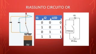
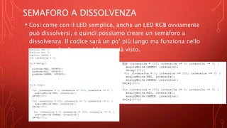
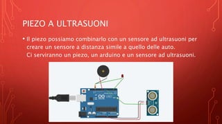
The document provides an introduction to programming with Arduino. It explains that Arduino is an open-source hardware and software platform used to build interactive electronic projects. It consists of a microcontroller board that can be programmed and used to read and control sensors, LEDs, motors and more. The document outlines the basic steps to get started which include downloading the Arduino IDE, installing drivers, selecting the board type, and uploading a test "Blink" program to make an LED turn on and off. It also provides explanations of some core electronic components like resistors, LEDs, sensors and describes how to set up a simple temperature sensing project and store the sensor readings in a database.
This document discusses robotics, Arduino, and microcontrollers. It defines robotics and explains that Arduino is an open-source hardware and software company that designs kits for building interactive devices. A microcontroller is described as a small computer on a single integrated circuit that contains memory, input/output peripherals, and a processor. The Atmel ATmega328P microcontroller on the Arduino Uno board is then outlined, noting its pins, memory, and functions. Finally, instructions for a basic "Blink" code example using an LED on pin 10 are provided.
The document provides an introduction to Arduino and physical computing using microcontrollers. It describes that Arduino boards use ATmega microcontrollers and can be programmed to sense the physical world using sensors, process data, and control physical devices using actuators. The document outlines the basic components of a microcontroller, how the Arduino programming environment works, and the basic structure and functions used in Arduino programs.
This document introduces Arduino by defining what it is, the parts of an Arduino board, and how to program it. An Arduino is a microcontroller board that can be used to develop interactive objects by taking various inputs (e.g. sensors) and controlling physical outputs (e.g. lights, motors). It explains the basic components of an Arduino board and how Arduino code is uploaded and run. A simple example is provided to blink an LED using Arduino code and by changing the delay times, the blinking speed can be adjusted. Keywords like Arduino board, sketch, and LED are also defined.
The document provides an overview of the Arduino platform, including what it is, what it is used for, and how to get started using it. Key points:
- Arduino is an open-source hardware and software platform for building interactive electronic projects through a simple programming language.
- It is used for physical computing projects, interactive installations, and rapid prototyping. Projects can include sensors and actuators.
- Getting started requires an Arduino board, USB cable, power supply, and downloading the IDE (integrated development environment) to write and upload code. Basic electrical safety knowledge is also important.
This document outlines an Arduino workshop. It includes an overview of the agenda which involves introductions, checking equipment, experimentation time, and creating personal projects. It then details introducing participants and encouraging collaboration. A list of included parts in the kits is provided. Instructions are given for installing the Arduino software and development environment. Examples are shown for breadboard layouts and code for simple projects like blinking an LED and reading input from a button. Additional experiments suggested include using sensors, LCD displays, motors, and programming an RGB LED with a joystick. Sources for parts, tutorials, and inspiration are listed to encourage continued learning.
The CMOS VLSI DESIGN PPT had the complete vision on VLSI Design styles in chip fabrication. It can give a good amount of knowledge to the students who needs VLSI Design
Arduino is an open-source hardware and software platform for building interactive electronic projects. It consists of a programmable microcontroller board and IDE software to write code. The board contains ports that can be configured as digital or analog inputs/outputs to interact with sensors, LEDs, motors and other components. Common Arduino boards include the Uno, Nano, Mega and Leonardo, which differ in processor, memory and I/O pins. The ATmega328P microcontroller on the Uno uses a Harvard architecture with separate memory and buses for instructions and data, allowing simultaneous access.
Richard Rixham introduces Arduino, an open source hardware and software platform that allows users to build physical computing devices ranging from flashing lights to robots. Arduino uses an inexpensive microcontroller board and IDE to make programming in C/C++ accessible. It has digital and analog pins that can interact with sensors and actuators. Common Arduino models include the Uno, Mini, and Mega. Shield add-on boards provide extra functions like wireless connectivity. Example projects and resources for learning more are provided.
A microcontroller is a computer on a single integrated chip that contains a processor, memory, and input/output ports. Common microcontroller families include Intel, Atmel, Microchip, and ARM. Microcontrollers are used in devices like cellphones, toys, appliances, cars, and cameras. The Arduino is a popular open-source hardware and software platform for building prototypes and interactive objects. It uses a simple programming language based on C/C++ and is inexpensive and easy to use.
The document discusses the Arduino integrated development environment (IDE). It states that Arduino is an open-source hardware and software platform that uses a microcontroller board that can be programmed. The Arduino IDE is used to write code and upload it to the physical board. Key features include reading analog/digital signals from sensors and outputting actions, uploading instructions to the microcontroller via the IDE, and loading new code onto the board using a USB cable without extra hardware. The Arduino IDE uses a simplified version of C++. Arduino programs are written in the IDE as sketches, based on a simplified version of the C language. Main parts of sketches include structure, values like variables and constants, and functions.
Arduino is an open-source hardware and software prototyping platform used for building electronics projects. It consists of a microcontroller board and an IDE used to write code. The board can be connected to sensors, actuators and other hardware components. There are many Arduino boards and derivatives that vary in size, capability, and function. The Arduino IDE uses a simplified version of C/C++ and provides an easy way to compile and upload code to the board.
The document discusses the Arduino open-source electronics prototyping platform. It describes what Arduino is, its programming environment, advantages, features, applications, and how it compares to other prototyping platforms. Arduino is an affordable and easy to use platform for creating interactive electronic projects through an open-source hardware board and software. It allows users to prototype sensors and control devices through code.
The document discusses the career prospects for graduating engineers in India's VLSI industry. It notes the growing demand for skilled VLSI engineers and the talent shortage India faces. It highlights the knowledge and skills gap in fresh graduates, including lack of VLSI design skills, problem solving, and soft skills. The document proposes that a holistic VLSI training program encompassing all key skills could help alleviate the talent crunch by making freshers job-ready for India's booming semiconductor industry.
Arduino is an open-source hardware platform for building interactive electronic projects. It consists of a simple open hardware design with an Atmel processor and input/output support. The hardware is less expensive than other prototyping devices. It is accompanied by a software side written in Java and based on Processing. Arduino began in Italy to control student-built interaction design projects and is descended from the open-source Wiring platform. It has a large community and potential for growth supporting its future success.
This document discusses the CMOS inverter. It explains the switch models of the CMOS inverter and how the input signals determine whether the NMOS or PMOS transistor is on. It also discusses the properties of static CMOS inverters, including their voltage transfer characteristic curve and noise margins. The document describes how process variations and supply voltage scaling can impact the inverter's performance. Finally, it examines the dynamic behavior of the CMOS inverter and the parasitic capacitances that affect its switching speeds.
The document discusses the Raspberry Pi, a small, inexpensive computer that can run various operating systems like Raspbian, Arch Linux, and Windows 10 IoT Core. It has 40 GPIO pins that allow users to connect external circuits and boards to control them using code. Example projects built with Raspberry Pi are described, such as a home media server, baby monitor, network-wide ad blocker, customized picture frame, automated pet feeder, and more.
Vikas Kumar has experience in designing and implementing various digital and analog circuits including a 32-bit RISC CPU using Verilog, an integrated round robin arbiter on an FPGA board, asynchronous and synchronous FIFOs for clock domain crossing, a two-stage op-amp using UMC 180nm technology, and a bandgap reference circuit. He has worked as an intern at KeenHeads Technologies and IISc Bangalore developing projects related to analog design, layout design, and an embedded security system. Vikas has skills in RTL coding, digital and analog design, layout design, Verilog, C/C++, MATLAB, and uses tools including Xilinx Vivado, Cad
Arduino is an open-source project that created microcontroller-based kits for building digital devices and interactive objects that can sense and control physical devices.
Here are some common applications of the Raspberry Pi:
- Home automation controller - Can be used to control devices like garage doors, lights, security cameras etc. using programming languages.
- Retro game console - Can emulate older game consoles and run retro games with the addition of controllers.
- Surveillance camera - Can be set up with a camera module to record video footage and detect motion.
- Media center - Can stream videos and music to a TV using OSes like OpenELEC or OSMC.
- Network device - Can be used as a router, firewall, file server, printer server etc. to add networking capabilities to older devices.
- Educational tool - Used to teach basic
This document discusses various designs for digital multipliers. It begins by reviewing the basic building blocks used in digital circuits and how binary multiplication works by adding partial products. It then describes approaches for implementing multiplication, including right shift and add serial multipliers and faster parallel array and tree multipliers. Booth encoding is introduced as a technique to reduce the number of stages in a multiplier. Implementation details are provided for array and Wallace tree multipliers, including the use of compression cells like the (4,2) counter. Optimization goals for multipliers differ from adders in emphasizing reducing the critical path.
This document presents a new CMOS voltage divider based current mirror and compares it to basic and cascode current mirrors. The basic current mirror has limitations like finite output resistance and channel length modulation effects. The cascode current mirror improves output resistance but wastes threshold voltage. The new CMOS voltage divider current mirror uses an NMOS and PMOS transistor voltage divider to bias an NMOS transistor and control the output current. It consumes less power than the basic current mirror and is well-suited for low current biasing applications.
By the end of this presentation you will be able to tell :
1. What is Arduino ?
2. Languages Supporting Arduino
3.Difference between microprocessor and microcontroller ?
4. Various different Arduino Boards
5. Arduino UNO R3 DataSheet
6. Parts and Functions of Arduino UNO R3 Board
7. Variables, functions and libraries used in Arduino board
8. Arduino Code: Blink Example
9. Applications of Arduino in real life
10. Simulators used for Arduino coding
The document provides an introduction to Arduino, including:
- What an Arduino is and its main components like a microprocessor, digital pins for inputs and outputs, and analog pins.
- How to program an Arduino using a processing "sketch" with setup, loop, and other functions like digitalWrite, analogWrite, and delay.
- Examples of inputs like sensors and outputs like LEDs.
- An overview of the Arduino programming language and block-based programming with ArduBlocks.
- Information on upcoming demonstrations of Arduino projects and links for further learning resources.
The document discusses the Raspberry Pi, a credit card-sized computer created by the Raspberry Pi Foundation to promote teaching computer science. It provides a brief history of its development by the Foundation. The document then covers the Raspberry Pi's hardware components, operating systems like Raspbian that can run on it, various programming languages that can be used, and applications like robotics, gaming and home automation. It compares the Raspberry Pi to the Arduino in terms of specifications and capabilities before concluding with potential future developments.
Una presentazione orientata a quanti hanno bisogno di avere una panoramica iniziale della piattaforma arduino con un approccio alla "prima faccio, poi torno su quello che ho fatto e capisco meglio" ;)
All'interno dei "LinoLab", laboratori digitali organizzati dal Centro Culturale "A. Zanussi" di Pordenone, le slide del laboratorio su Arduino. Livello principianti.
maggio 2016
Slide del corso Arduino Base tenuto presso il Museo della Scienza e Tecnologia "Leonardo da Vinci" di Milano.
Argomenti trattati:
- I componenti elettronici di base
- Introduzione alla scheda Arduino
- Le basi della programmazione
- Le comunicazioni seriali
- Input digitali e analogici semplici
- Ricavare input dai sensori
- L’output visivo
- L’output fisico
Corso di 20 ore sulla piattaforma Arduino. Corso tenuto nelle scuole superiori di San Secondo e Fornovo come corso di aggiornamento per il personale docente. Il corso si suddivide in 5 lezioni dove vengono spiegate più o meno tutte le funzionalità della piattaforma. I file li potete trovare al seguente indirizzo https://github.com/loweherz/ArduinoLessons
Arduino, workshop di due giorni: materiale didattico.
ARGOMENTI:
- basi della programmazione di Arduino
- fondamenti di elettronica
- interagire con sistemi di input
- interagire con sistemi di output
- comunicazione seriale con processing
** E' possibile scaricare tutto il codice degli esercizi: https://github.com/hold3n/Arduino-Basic-Workshop
CC 2014 Daniele Iori e Ivan De Cesaris per Officine Giardino. Quest'opera è distribuita con Licenza Creative Commons Attribuzione - Condividi allo stesso modo 4.0 Internazionale.
Corso di 20 ore sulla piattaforma Arduino. Corso tenuto nelle scuole superiori di San Secondo e Fornovo come corso di aggiornamento per il personale docente. Il corso si suddivide in 5 lezioni dove vengono spiegate più o meno tutte le funzionalità della piattaforma. I file li potete trovare al seguente indirizzo https://github.com/loweherz/ArduinoLessons
Using GHI FEZ Robot Kit I have created a simple robot that it can move automatically. It can also skip obstacles along its path. To detect obstacles I have used two distance detector sensor; so when the robot detect an obstacles it turn in the opposite direction. Into the FEZ Robot Kit you can find all you need to build your robot: fez mini board, motor control, distance sensor, robot chassis, motor, etc ...). If you use a fez domino/panda board instead of the fez robot kit; you must add a motor control board to control your motors (for example a pololu dual motor driver). - www.dotnettoscana.org/fez-robot-kit.aspx - www.youtube.com/watch?v=Ik1hGJl2BkE
Dai concetti di base ai primi componenti e alla legge di ohm. Per capire come si conporta la corrente elettrica e la tensione, cos'è una resistenza. Mini guida per riconoscere le componenti elettroniche e realizzare i primi semplici circuiti.
2. CHE COS’È UN LED?
• LED è l'acronimo di "light-emitting
diode" ovvero diodo ad emissione
luminosa. Deve essere alimentati a
corrente costante e polarizzata.
COSA POSSIAMO
FARE CON UN LED?
Con un led ed altri componenti si
possono creare infiniti circuiti. Noi
abbiamo svolto 3 lavori:
- Accendere un led con una batteria da
9v
- Accendere un led con patate o limoni
- Usare il potenziometro in un circuito
con un LED
3. LED ACCESO DA UNA
BATTERIA DI 9 VOLT
TRAMITE TINKERCAD, ABBIAMO PROVATO AD ACCENDERE UN LED
CON UNA BATTERIA DA 9 VOLT
4. L’ESPLOSIONE DEL LED
Collegando la batteria di 9v direttamente al led
(l’anodo alla parte positiva e il catodo alla parte
negativa). facendo cosi il led esploderebbe perché
perché il voltaggio è troppo alto.
LA RESISTENZA CI
PERMETTE DI ACCENDERE
IL LED
Applicando una resistenza tra il led e la
batteria viene limitato il passaggio della
corrente elettrica e arriva una quantità di
corrente giusta per far accendere il led.
SCHEMA DEL CIRCUITO
APPENA ESEGUITO
Per descrivere meglio un circuito si
utilizza uno schema che indichi gli
elementi attivi e passivi e le loro
connessioni
5. QUANTE PATATE SERVONO
PER ACCENDERE UN LED?
È POSSIBILE ACCENDERE UN LED CON UNA PATATA? SE SI, QUANTE
NE SERVONO?
6. UNA SOLA PATATA NON BASTA
PER ACCENDERE IL LED
Collegando una sola patata al led,
quest’ultimo non si accende a causa dello
scarso voltaggio della patata
DUE PATATE ACCENDONO IL
LED
Collegando due patate in serie il voltaggio
delle due patate si somma e il led riceve una
quantità di voltaggio sufficiente per
accendersi, anche se emana una luce molto
leggera a causa del voltaggio non troppo alto
COLLEGAMENTO IN SERIE E IN
PARALLELO
Si parla di collegamento in serie quando due o più componenti sono
collegati in modo da formare un percorso unico per la corrente
elettrica che li attraversa.
Si parla di collegamento in parallelo quando i componenti sono
collegati ad una coppia di conduttori in modo che la tensione
elettrica sia applicata a tutti quanti allo stesso modo.
7. REGOLARE LA
RESISTENZA CON IL
POTENZIOMETRO
COME ULTIMO LAVORO UTILIZZIAMO IL
POTENZIOMETRO IN UN CIRCUITO CON LED E
BATTERIA DA 9V PER REGOLARE LA RESISTENZA
CHE COS’È UN POTENZIOMETRO?
Un potenziometro è un componente elettrico che
agisce come divisore di tensione variabile. Di solito
hanno tre terminali, uno dei quali è collegato con la
manopola di regolazione.
8. POTENZIOMETRO
REGOLATO AL MINIMO
Come possiamo vedere
dall’immagine, regolando il
potenziometro al minimo, la
resistenza è bassissima e il led
esplode
AUMENTIAMO LA
REGOLAZIONE ED
AUMENTA LA
RESISTENZA
Regolando il potenziometro su
una maggiore resistenza, mano a
mano vedremo che il led emanerà
sempre meno luce, lo si nota
meglio dal susseguirsi delle
immagini.
9. CIRCUITO AND E CIRCUITO
OR
IL CIRCUITO AND E IL CIRCUITO OR SONO DUE CIRCUITI CHE HANNO
LA STESSA FUNZIONE, NEL NOSTRO CASO QUELLA DI ACCENDERE UN
LED, MA CHE COMPIONO L’AZIONE IN MODO DIVERSO.
10. IL CIRCUITO AND
La caratteristica di un circuito AND è quella
di avere 2 interruttori collegati in serie. In
questo caso, per accendere il LED, bisogna
accendere entrambi gli interruttori.
Facendo cosi, il LED riceve come INPUT due
valori di ingresso pari a 1. Ma cosa vuol
dire valore di ingresso 1?
LA TABELLA DI
VERITÀ DELL’AND
Le tabelle della verità (o tabelle
logiche) sono tabelle usate nella logica
per determinare se una determinata
proposizione è vera o falsa. Il valore 1
indica il VERO mentre lo 0 indica il
FALSO. Nel caso dell’elettronica l’1
rappresenta l’accensione di un
dispositivo. Ricapitolando, con un
collegamento in serie, il LED per avere
1 come valore serve che entrambi gli
SCHEMA DEL CIRCUITO
AND
TABELLA DI VERITÀ DEL
CIRCUITO AND
11. IL CIRCUITO OR
Al contrario di quello AND, la
caratteristica di un circuito OR è
quella di avere due interruttori
collegati in parallelo, di
conseguenza basta solo l’input di
uno dei due per far accendere il
LED.
LA TABELLA DI
VERITÀ DELL’OR
Ora che gia sappiamo cos’è e come
funziona la tabella della verità, basta
solamente sapere che nella tabella della
verità dell’OR, basta solo un valore su due
VERO per ottenere VERO come risultato.
Quindi con il collegamento in parallelo, il
LED ottiene 1 quando almeno un
interruttore dà valore 1
SCHEMA DI CIRCUITO
OR
TABELLA DI VERITÀ DEL
CIRCUITO OR
12. CIRCUITO AND IN FUNZIONE SU TINKERCAD
Dopo aver visto cos’è e come funziona un circuito AND, lo pratichiamo su
Tinkercad e vediamo che funziona esattamente come è stato detto in
precedenza; per accendere il LED entrambi gli interruttori devono essere attivi.
CIRCUITO
SPENTO
CIRCUITO CON UN
INTERRUTTORE ACCESO (LED
SPENTO)
IL LED SI ACCENDE CON
L’ATTIVAZIONE DI ENTRAMBI
GLI INTERRUTTORI
13. LA TABELLA DI VERITÀ DELL’AND NELLA
PRATICA
Dopo aver
spiegato cos’è una
tabella della verità
dell’AND, ecco un
breve video per far
capire ancor più
semplicemente
come funziona,
con l’ausilio di
Tinkercad.
14. CIRCUITO OR IN FUNZIONE SU TINKERCAD
Dopo aver verificato il circuito AND, andiamo a praticare anche il circuito OR
su Tinkercad, in questo caso basterà solamente un interruttore attivo per far
accendere il LED
CIRCUITO
SPENTO
IL LED SI ACCENDE CON
L’INPUT DI UN SOLO
INTERRUTTORE
15. LA TABELLA DI VERITÀ DELL’OR NELLA
PRATICA
E dopo la
tabella di verità
dell’AND, anche
per quella
dell’OR c’è un
video realizzato
su Tinkercad
per semplificare
l’apprendiment
o
18. PROGRAMMARE IN ARDUINO SU
TINKERCAD
• Prima di programmare un arduino vero e proprio, è consigliato
fare molta pratica su Tinkercad, un ambiente di sviluppo
virtuale sul quale possiamo lavorare sia sulla parte hardware
che su quella software.
• Il primo lavoro da fare è quello di riprodurre un led
lampeggiante.
19. LA PARTE HARDWARE
• Prima di iniziare a programmare, ovviamente, dobbiamo creare
il nostro circuito e potremo scegliere tra una vasta selezione di
componenti, qui di sotto troverete la componente hardware del
led lampeggiante.
20. LA PROGRAMMAZIONE
• Una volta composto il circuito, non ci resta che programmare
l’arduino e dirgli cosa fare, cosi come vedete nell’immagine
seguente, nella quale c’è un esempio di codice che fa
lampeggiare un LED.
Una volta fatto ciò, basterà avviare la
simulazione e il led inizierà a
lampeggiare.
21. REALIZZARE UN SEMAFORO IN ARDUINO
• Grazie ai LED RGB, che emettono luci di diverse colori,
possiamo realizzare un semaforo con Arduino.
Nell’immagine, la componente hardware.
22. IL CODICE
• Qui di fianco, il codice per
realizzare il semaforo. Per la prima
volta incontriamo le Costanti.
#define RED 8
#define GREEN 2
#define BLU 7
void setup()
{
pinMode(RED,OUTPUT);
pinMode(BLU,OUTPUT);
pinMode(GREEN,OUTPUT);
}
void loop()
{
//combinazione per il rosso
digitalWrite(RED, HIGH);
digitalWrite(BLU, LOW);
digitalWrite(GREEN, LOW);
delay(1200);
//combinazione per il verde
digitalWrite(RED, LOW);
digitalWrite(GREEN, HIGH);
digitalWrite(BLU, LOW);
delay(1200);
//combinazione per il giallo
digitalWrite(GREEN, HIGH);
digitalWrite(RED, HIGH);
digitalWrite(BLU, LOW);
delay(1200);
}
23. COSTANTI E VARIABILI
• Le costanti vengono indicate con #define NOMECOSTANTE 1(o
qualsiasi altro numero), e una volta creata una costante, ogni
volta che il codice leggerà il nome scelto, la sostituirà con il
numero che abbiamo indicato.
• Le variabili si indicano con int NOMEVARIABILE = 0, cosi
facendo creeremo un valore che come dice il nome, varia, e
quindi può aumentare o diminuire.
24. LE FUNZIONI
LE FUNZIONI CHE DICHIARIAMO IN UN CODICE POSSONO ESSERE DI
QUATTRO TIPI.
FUNZIONE CHE NON
PRENDE E NON
RESTITUISCE NULLA
FUNZIONE CHE PRENDE
VALORI MA NON NE
RESTITUISCE NESSUNO
FUNZIONE CHE NON
PRENDE NULLA MA
RESTITUISCE UN VALORE
FUNZIONE CHE PRENDE
DEI VALORI E NE
RESISTUISCE ALTRI
25. LED A DISSOLVENZA
• Sull’arduino troviamo alcuni pin analogici che ci permettono di
decidere quanta intensità dare al led, cosi facendo e aiutandoci
con quale funzione, possiamo creare un led a dissolvenza. La
componente hardware è sempre la solita.
26. CODICE
• Nel codice troviamo variabili e
costanti che abbiamo già visto
precedentemente, troviamo la
funzione analogwrite che
permette di dare una certa
quantità di intensità al LED, a
differenza di digitalwrite.
La funzione «for» ci aiuta a non
dover ripetere più volte il codice.
27. SEMAFORO A DISSOLVENZA
• Cosi come con il LED semplice, anche un LED RGB ovviamente
può dissolversi, e quindi possiamo creare un semaforo a
dissolvenza. Il codice sarà un po’ più lungo ma funziona nello
stesso modo di come abbiamo già visto.
28. PIEZO MELODY
• Dopo aver svolto lavori con i led, cambiamo i nostri
componenti hardware e andiamo sui sintetizzatori vocali.
Anche queste componenti è possibile trovarle su Tinkercad.
29. CODICE
• Nel codice troviamo «map», una funzione che ci
permette di proporzionare l’unità di misura che
riceve il piezo, con quelle che invia l’arduino.
30. FAR CANTARE IL PIEZO
• Con il piezo possiamo riprodurre vere e proprie note e quindi
anche delle canzoni, nel codice che vedremo, riprodurremo
l’inno alla gioia.
La parte hardware comprende piezo e arduino.
31. IL CODICE
• Il codice è leggermente
complesso e troviamo nuove
funzioni come «tone», inoltre
incontriamo gli array, ovvero
elenchi di variabili.
32. PIEZO A ULTRASUONI
• Il piezo possiamo combinarlo con un sensore ad ultrasuoni per
creare un sensore a distanza simile a quello delle auto.
Ci serviranno un piezo, un arduino e un sensore ad ultrasuoni.
33. CODICE
• Il codice farà si che più
l’ostacolo è vicino, maggiore
sarà il rumore prodotto dal
piezo. In questo caso ci
troviamo per la prima volta
davanti ad un sensore ad
ultrasuoni e quindi nel
codice vedremo anche come
configurarlo.
34. MIXER DI COLORI
• Cominciamo a svolgere lavori più complessi, iniziando col
mixer di colore. Per farlo ci serviranno 3 potenziometri, una
batteria da 9v e un arduino.
Ciascun potenziometro corrisponderà ad un colore, cosi
potremo mischiarli tra loro e anche deciderne l’intensità.
35. CODICE
• Nel codice troviamo per la prima
volta l’if, funzione molto
importante che troveremo
praticamente ovunque nella
nostra vita. Consiste nel
compiere qualcosa al verificarsi
di una condizione.
36. LISTNER
• Come prossimo esercizio abbiamo il listner, che è molto
importante perché è la base di tutti i sistemi domotici. Si chiama
listner proprio perché lui «ascolta» e agisce di conseguenza. In
questo caso il nostro listner accenderà o spegnerà i led a seconda
del comando ricevuto.
37. CODICE
• Tralasciando le varie funzioni che
già conosciamo, la cosa più
importante del listner è lo switch
case, che è una funzione che ci
permettere di aggiungere sempre
più condizioni che hanno
un’azione collegata, invece di
dover ripetere ogni volta «if…».
38. CREARE UN PRIMO
PROTOTIPO DI ROBOT
COME ESERCITAZIONE FINALE, HAI IL COMPITO DI CREARE UN VERO
E PROPRIO ROBOT TUTTO TUO. DOPO AVER SVOLTO TANTI ESERCIZI
DIVERSI CON PICCOLI CODICI, AVRAI SICURAMENTE LE
COMPETENZE PER SVILJUPPARE CODICI SEMPRE PIÙ COMPLESSI PER
PROGRAMMARE VERI ROBOT
39. LA FUNZIONE DEI MOTORI A CORRENTE
CONTINUA
• È importante saper utilizzare bene i motori dato che sono un metodo di
spostamento molto importante per la costruzione di robot.
Un motore con i morsetti collegati nel modo corretto ruoterà in senso orario, una
volta alimentato. Se colleghiamo il morsetto positivo al negativo e il morsetto
negativo al positivo, ruoterà in senso antiorario.
Per gestire entrambi i morsetti come pin, utilizziamo un ponte H.
40. FAR MUOVERE IL ROBOT IN AVANTI, IN
DIETRO, A DESTRA E A SINISTRA.
• La direzione in cui andrà il nostro robottino dipenderà totalmente
dai motori e dalla loro direzione. Prendiamo come esempio un
robot con due motori.
• VA AVANTI: Quando entrambi i motori vanno in senso orario.
• VA INDIETRO: Quando entrambi i motori vanno in senso antiorario.
• VA A SINISTRA: Quando il motore destro va in senso orario, mentre
quello sinistro in senso antiorario.
• VA A DESTRA: Quando il motore sinistro va in senso orario mentre
quello destro in senso antiorario
41. TELECOMANDO PER FAR MUOVERE IL
ROBOT
• Possiamo comandare il movimento di un robot con il listener.
Quest’ultimo consiste nel leggere ciò che viene scritto sulla seriale
(o sul wifi/bluetooth) e per ogni input ha delle istruzioni precise,
ad esempio se il listener riceve…
«A» il robot va avanti
«I» il robot va indietro
«D» il robot va a destra
«S» il robot va a sinistra
• Collegando il robot via wifi, potremo usare dispositivi connessi alla
medesima rete per manovrare il robot, magari creando
un’applicazione specifica che fa da telecomando.
• Facendo tutto questo, abbiamo costruito un vero e proprio robot.
43. GRAZIE PER LA LETTURA
Presentazione realizzata da Vincenzo
Esposito
Trovi altre guide dedicate ad Arduino e al
mondo della robotica sul sito
amedeolepore.com