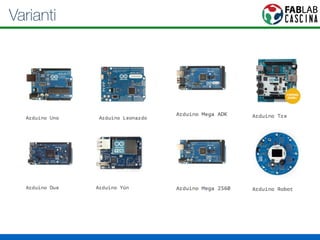
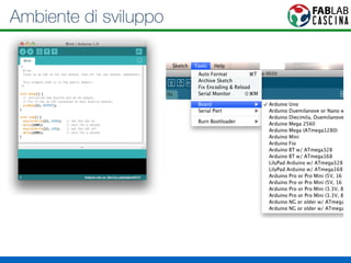
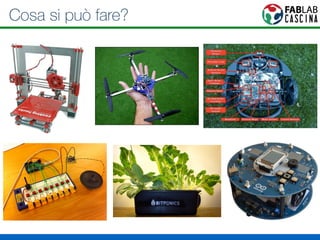
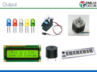
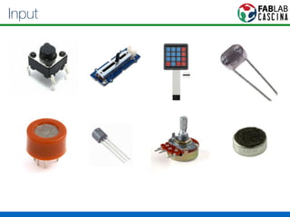
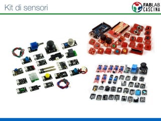
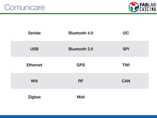
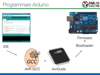
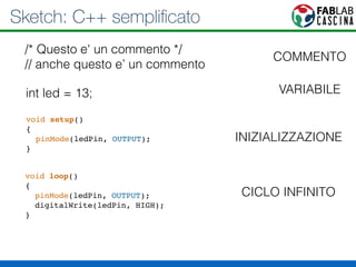
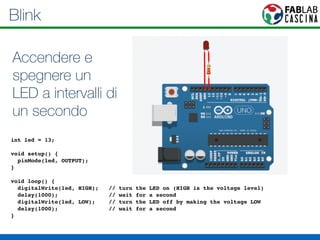
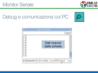
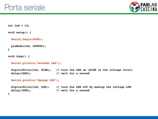
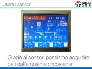
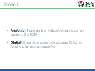
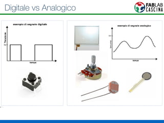
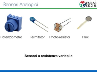
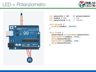
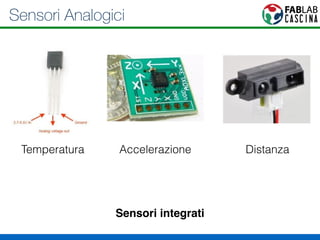
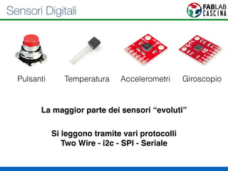
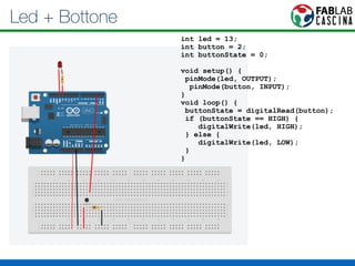
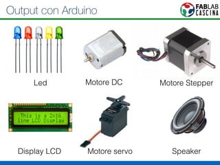
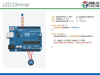
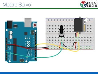
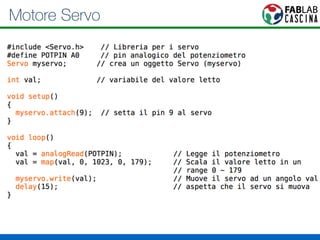
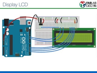
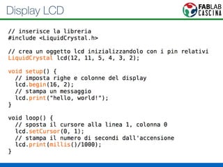
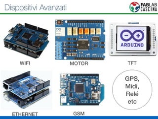
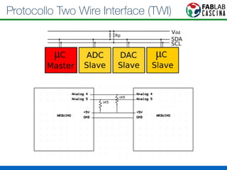
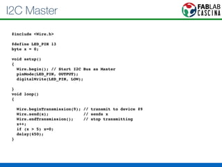
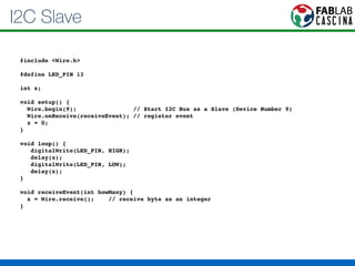
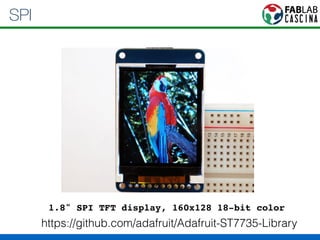
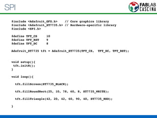
Arduino 101 
Fiore Basile 
fiore.basile@gmail.com
Cos’è Arduino? 
• Una (serie) di schede elettroniche 
• Ambiente di sviluppo 
• Una community
La Scheda
Microcontroller - Famiglia AVR
Varianti
Cloni
Ambiente di sviluppo
Community 
http://playground.arduino.cc
Cosa si può fare?
Output
Input
Kit di sensori
Comunicare 
Seriale Bluetooth 4.0 I2C 
USB Bluetooth 2.0 SPI 
Ethernet GPS TWI 
Wifi RF CAN 
Zigbee Midi
123D Circuits 
http://123d.circuits.io/
Programmare Arduino 
IDE 
AVR GCC AvrDude 
Firmware 
+ 
Bootloader 
+
Sketch: C++ semplificato 
/* Questo e' un commento */ 
// anche questo e’ un commento 
int led = 13; 
void setup()! 
{! 
pinMode(ledPin, OUTPUT);! 
} 
void loop()! 
{! 
pinMode(ledPin, OUTPUT);! 
digitalWrite(ledPin, HIGH);! 
} 
COMMENTO 
VARIABILE 
INIZIALIZZAZIONE 
CICLO INFINITO
Blink 
Accendere e 
spegnere un 
LED a intervalli di 
un secondo 
! 
int led = 13;! 
! 
void setup() { ! 
pinMode(led, OUTPUT); ! 
}! 
! 
void loop() {! 
digitalWrite(led, HIGH); // turn the LED on (HIGH is the voltage level)! 
delay(1000); // wait for a second! 
digitalWrite(led, LOW); // turn the LED off by making the voltage LOW! 
delay(1000); // wait for a second! 
}!
Monitor Seriale 
Debug e comunicazione col PC
Porta seriale 
! 
int led = 13;! 
! 
void setup() { ! 
! 
Serial.begin(9600);! 
! 
pinMode(led, OUTPUT); ! 
}! 
! 
void loop() {! 
! 
Serial.println(“Accendo LED”);! 
! 
digitalWrite(led, HIGH); // turn the LED on (HIGH is the voltage level)! 
delay(1000); // wait for a second! 
! 
Serial.println(“Spengo LED”);! 
! 
digitalWrite(led, LOW); // turn the LED off by making the voltage LOW! 
delay(1000); // wait for a second! 
}!
Usare i sensori 
Grazie ai sensori possiamo acquisire 
dati dall’ambiente circostante
Sensori 
• Analogici: Il segnale è un voltaggio misurato con un 
valore da 0 a 1024 
• Digitali: Il segnale è sempre un voltaggio (0-5v) ma 
Arduino ci fornisce un valore 0 o 1
Digitale vs Analogico
Sensori Analogici 
Potenziometro Termitstor Photo-resistor Flex 
Sensori a resistenza variabile
LED + Potenziometro 
int sensorPin = A0; // potenziometro 
int ledPin = 13; // LED 
int sensorValue = 0; // VALORE 
! 
void setup() { 
pinMode(ledPin, OUTPUT); 
} 
! 
void loop() { 
sensorValue = analogRead(sensorPin); 
digitalWrite(ledPin, HIGH); 
delay(sensorValue); 
digitalWrite(ledPin, LOW); 
delay(sensorValue); 
}
Sensori Analogici 
Temperatura Accelerazione Distanza 
Sensori integrati
Sensori Digitali 
Pulsanti Temperatura Accelerometri Giroscopio 
La maggior parte dei sensori “evoluti” 
Si leggono tramite vari protocolli 
Two Wire - i2c - SPI - Seriale
Led + Bottone 
int led = 13; 
int button = 2; 
int buttonState = 0; 
! 
void setup() { 
pinMode(led, OUTPUT); 
pinMode(button, INPUT); 
} 
void loop() { 
buttonState = digitalRead(button); 
if (buttonState == HIGH) { 
digitalWrite(led, HIGH); 
} else { 
digitalWrite(led, LOW); 
} 
}
Output con Arduino 
Led Motore DC Motore Stepper 
Display LCD Motore servo Speaker
Output con Arduino
PWM 
Variando l’intervallo acceso-spento
PWM 
• Possiamo controllare la luminosità di un LED 
• Possiamo controllare un Motore Passo-Passo 
• Possiamo controllare un Servo Motore 
• Possiamo pilotare uno speaker
Uscite PWM
LED Dimmer 
int sensorPin = A0; // potenziometro 
int ledPin = 13; // LED 
int sensorValue = 0; // VALORE 
! 
void setup() { 
pinMode(ledPin, OUTPUT); 
} 
! 
void loop() { 
sensorValue = analogRead(sensorPin); 
// input 0-1024 output 0-255 
analogWrite(ledPin, sensorValue/4); 
}
Motore Servo
Motore Servo
Display LCD
Display LCD
Dispositivi Avanzati 
WIFI MOTOR TFT 
ETHERNET GSM 
GPS, 
Midi, 
Relé 
etc
Protocolli di comunicazione 
• One Wire 
• I2C SDA/SCK 
• SPI MISO/MOSI/CLK/SS 
• Seriale TX-RX
DHT11 - Sensore Umidità - One Wire 
#include <dht11.h>! 
! 
dht11 DHT11;! 
#define DHT11PIN 2! 
int chk = DHT11.read(DHT11PIN);! 
! 
Serial.print("Read sensor: ");! 
switch (chk)! 
{! 
case DHTLIB_OK: ! 
! ! Serial.println("OK"); ! 
! ! break;! 
case DHTLIB_ERROR_CHECKSUM: ! 
! ! Serial.println("Checksum error"); ! 
! ! break;! 
case DHTLIB_ERROR_TIMEOUT: ! 
! ! Serial.println("Time out error"); ! 
! ! break;! 
default: ! 
! ! Serial.println("Unknown error"); ! 
! ! break;! 
}! 
http://playground.arduino.cc/main/DHT11Lib
Protocollo Two Wire Interface (TWI)
I2C Master 
#include <Wire.h>! 
! 
#define LED_PIN 13! 
byte x = 0;! 
! 
void setup()! 
{! 
Wire.begin(); // Start I2C Bus as Master! 
pinMode(LED_PIN, OUTPUT);! 
digitalWrite(LED_PIN, LOW);! 
! 
}! 
void loop()! 
{! 
! 
Wire.beginTransmission(9); // transmit to device #9! 
Wire.send(x); // sends x ! 
Wire.endTransmission(); // stop transmitting! 
x++;! 
if (x > 5) x=0;! 
delay(450);! 
}
I2C Slave 
#include <Wire.h>! 
! 
#define LED_PIN 13! 
! 
int x;! 
! 
void setup() {! 
Wire.begin(9); // Start I2C Bus as a Slave (Device Number 9)! 
Wire.onReceive(receiveEvent); // register event! 
x = 0;! 
}! 
! 
void loop() {! 
digitalWrite(LED_PIN, HIGH);! 
delay(x);! 
digitalWrite(LED_PIN, LOW);! 
delay(x);! 
}! 
! 
void receiveEvent(int howMany) {! 
x = Wire.receive(); // receive byte as an integer! 
}
SPI 
1.8" SPI TFT display, 160x128 18-bit color 
https://github.com/adafruit/Adafruit-ST7735-Library
SPI 
#include <Adafruit_GFX.h> // Core graphics library! 
#include <Adafruit_ST7735.h> // Hardware-specific library! 
#include <SPI.h>! 
! 
#define TFT_CS 10! 
#define TFT_RST 9 ! 
#define TFT_DC 8! 
! 
Adafruit_ST7735 tft = Adafruit_ST7735(TFT_CS, TFT_DC, TFT_RST);! 
!! 
void setup(){! 
tft.initR(); ! 
}! 
! 
void loop(){! 
! 
tft.fillScreen(ST7735_BLACK);! 
! 
tft.fillRoundRect(25, 10, 78, 60, 8, ST7735_WHITE);! 
! 
tft.fillTriangle(42, 20, 42, 60, 90, 40, ST7735_RED);! 
! 
}
Altri esempi 
http://arduino.cc/en/Tutorial/HomePage 
http://github.com/adafruit
Grazie! 
Fiore Basile 
fiore.basile@gmail.com 
http://fibasile.github.io 
http://fablabcascina.org 
http://fabbricalo.it

Workshop Arduino by Fiore Basile

  • 1.
    Arduino 101 FioreBasile fiore.basile@gmail.com
  • 2.
    Cos’è Arduino? •Una (serie) di schede elettroniche • Ambiente di sviluppo • Una community
  • 4.
  • 5.
  • 6.
  • 8.
  • 9.
  • 10.
  • 11.
  • 12.
  • 13.
  • 14.
  • 15.
    Comunicare Seriale Bluetooth4.0 I2C USB Bluetooth 2.0 SPI Ethernet GPS TWI Wifi RF CAN Zigbee Midi
  • 16.
  • 17.
    Programmare Arduino IDE AVR GCC AvrDude Firmware + Bootloader +
  • 18.
    Sketch: C++ semplificato /* Questo e' un commento */ // anche questo e’ un commento int led = 13; void setup()! {! pinMode(ledPin, OUTPUT);! } void loop()! {! pinMode(ledPin, OUTPUT);! digitalWrite(ledPin, HIGH);! } COMMENTO VARIABILE INIZIALIZZAZIONE CICLO INFINITO
  • 19.
    Blink Accendere e spegnere un LED a intervalli di un secondo ! int led = 13;! ! void setup() { ! pinMode(led, OUTPUT); ! }! ! void loop() {! digitalWrite(led, HIGH); // turn the LED on (HIGH is the voltage level)! delay(1000); // wait for a second! digitalWrite(led, LOW); // turn the LED off by making the voltage LOW! delay(1000); // wait for a second! }!
  • 20.
    Monitor Seriale Debuge comunicazione col PC
  • 21.
    Porta seriale ! int led = 13;! ! void setup() { ! ! Serial.begin(9600);! ! pinMode(led, OUTPUT); ! }! ! void loop() {! ! Serial.println(“Accendo LED”);! ! digitalWrite(led, HIGH); // turn the LED on (HIGH is the voltage level)! delay(1000); // wait for a second! ! Serial.println(“Spengo LED”);! ! digitalWrite(led, LOW); // turn the LED off by making the voltage LOW! delay(1000); // wait for a second! }!
  • 22.
    Usare i sensori Grazie ai sensori possiamo acquisire dati dall’ambiente circostante
  • 23.
    Sensori • Analogici:Il segnale è un voltaggio misurato con un valore da 0 a 1024 • Digitali: Il segnale è sempre un voltaggio (0-5v) ma Arduino ci fornisce un valore 0 o 1
  • 24.
  • 25.
    Sensori Analogici PotenziometroTermitstor Photo-resistor Flex Sensori a resistenza variabile
  • 26.
    LED + Potenziometro int sensorPin = A0; // potenziometro int ledPin = 13; // LED int sensorValue = 0; // VALORE ! void setup() { pinMode(ledPin, OUTPUT); } ! void loop() { sensorValue = analogRead(sensorPin); digitalWrite(ledPin, HIGH); delay(sensorValue); digitalWrite(ledPin, LOW); delay(sensorValue); }
  • 27.
    Sensori Analogici TemperaturaAccelerazione Distanza Sensori integrati
  • 28.
    Sensori Digitali PulsantiTemperatura Accelerometri Giroscopio La maggior parte dei sensori “evoluti” Si leggono tramite vari protocolli Two Wire - i2c - SPI - Seriale
  • 29.
    Led + Bottone int led = 13; int button = 2; int buttonState = 0; ! void setup() { pinMode(led, OUTPUT); pinMode(button, INPUT); } void loop() { buttonState = digitalRead(button); if (buttonState == HIGH) { digitalWrite(led, HIGH); } else { digitalWrite(led, LOW); } }
  • 30.
    Output con Arduino Led Motore DC Motore Stepper Display LCD Motore servo Speaker
  • 31.
  • 32.
  • 33.
    PWM • Possiamocontrollare la luminosità di un LED • Possiamo controllare un Motore Passo-Passo • Possiamo controllare un Servo Motore • Possiamo pilotare uno speaker
  • 34.
  • 35.
    LED Dimmer intsensorPin = A0; // potenziometro int ledPin = 13; // LED int sensorValue = 0; // VALORE ! void setup() { pinMode(ledPin, OUTPUT); } ! void loop() { sensorValue = analogRead(sensorPin); // input 0-1024 output 0-255 analogWrite(ledPin, sensorValue/4); }
  • 36.
  • 37.
  • 38.
  • 39.
  • 40.
    Dispositivi Avanzati WIFIMOTOR TFT ETHERNET GSM GPS, Midi, Relé etc
  • 41.
    Protocolli di comunicazione • One Wire • I2C SDA/SCK • SPI MISO/MOSI/CLK/SS • Seriale TX-RX
  • 42.
    DHT11 - SensoreUmidità - One Wire #include <dht11.h>! ! dht11 DHT11;! #define DHT11PIN 2! int chk = DHT11.read(DHT11PIN);! ! Serial.print("Read sensor: ");! switch (chk)! {! case DHTLIB_OK: ! ! ! Serial.println("OK"); ! ! ! break;! case DHTLIB_ERROR_CHECKSUM: ! ! ! Serial.println("Checksum error"); ! ! ! break;! case DHTLIB_ERROR_TIMEOUT: ! ! ! Serial.println("Time out error"); ! ! ! break;! default: ! ! ! Serial.println("Unknown error"); ! ! ! break;! }! http://playground.arduino.cc/main/DHT11Lib
  • 43.
    Protocollo Two WireInterface (TWI)
  • 44.
    I2C Master #include<Wire.h>! ! #define LED_PIN 13! byte x = 0;! ! void setup()! {! Wire.begin(); // Start I2C Bus as Master! pinMode(LED_PIN, OUTPUT);! digitalWrite(LED_PIN, LOW);! ! }! void loop()! {! ! Wire.beginTransmission(9); // transmit to device #9! Wire.send(x); // sends x ! Wire.endTransmission(); // stop transmitting! x++;! if (x > 5) x=0;! delay(450);! }
  • 45.
    I2C Slave #include<Wire.h>! ! #define LED_PIN 13! ! int x;! ! void setup() {! Wire.begin(9); // Start I2C Bus as a Slave (Device Number 9)! Wire.onReceive(receiveEvent); // register event! x = 0;! }! ! void loop() {! digitalWrite(LED_PIN, HIGH);! delay(x);! digitalWrite(LED_PIN, LOW);! delay(x);! }! ! void receiveEvent(int howMany) {! x = Wire.receive(); // receive byte as an integer! }
  • 46.
    SPI 1.8" SPITFT display, 160x128 18-bit color https://github.com/adafruit/Adafruit-ST7735-Library
  • 47.
    SPI #include <Adafruit_GFX.h>// Core graphics library! #include <Adafruit_ST7735.h> // Hardware-specific library! #include <SPI.h>! ! #define TFT_CS 10! #define TFT_RST 9 ! #define TFT_DC 8! ! Adafruit_ST7735 tft = Adafruit_ST7735(TFT_CS, TFT_DC, TFT_RST);! !! void setup(){! tft.initR(); ! }! ! void loop(){! ! tft.fillScreen(ST7735_BLACK);! ! tft.fillRoundRect(25, 10, 78, 60, 8, ST7735_WHITE);! ! tft.fillTriangle(42, 20, 42, 60, 90, 40, ST7735_RED);! ! }
  • 48.
  • 49.
    Grazie! Fiore Basile fiore.basile@gmail.com http://fibasile.github.io http://fablabcascina.org http://fabbricalo.it