Here are the key points about HP ArcSight Management Center:
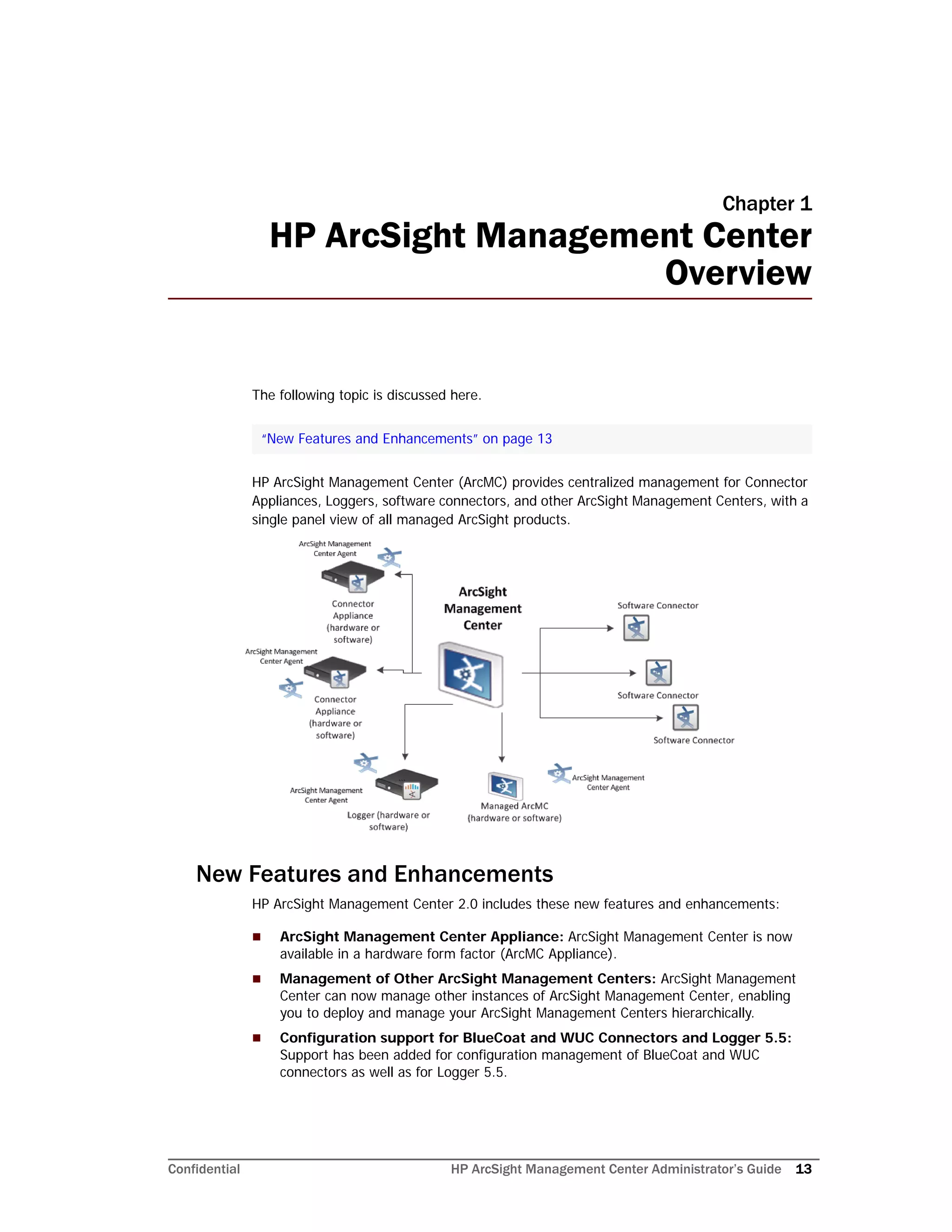
- ArcMC provides centralized management for Connector Appliances, Loggers, software connectors, and other ArcSight products. This allows for simplified configuration, monitoring, updating, and reporting of these products from a single console.
- It allows administrators to remotely manage multiple distributed ArcSight products from a central location. This reduces the effort required to manage large deployments.
- Common tasks that can be performed through ArcMC include configuring connectors and destinations, managing configurations, pushing updates, monitoring product health and performance, managing backups/restores, and more.
- ArcMC supports both software and appliance-based deployments. The software version install


![2 Software Installation
Confidential HP ArcSight Management Center Administrator’s Guide 21
---------------------
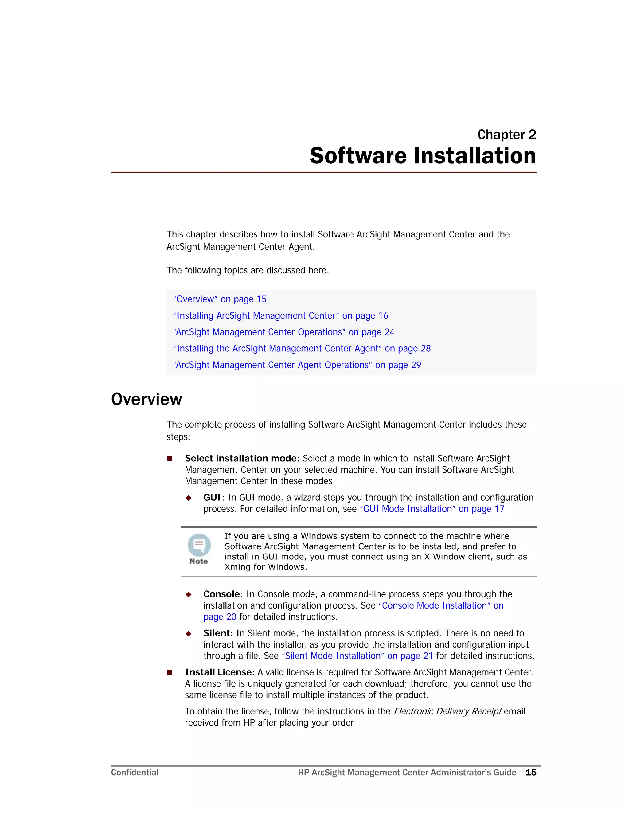
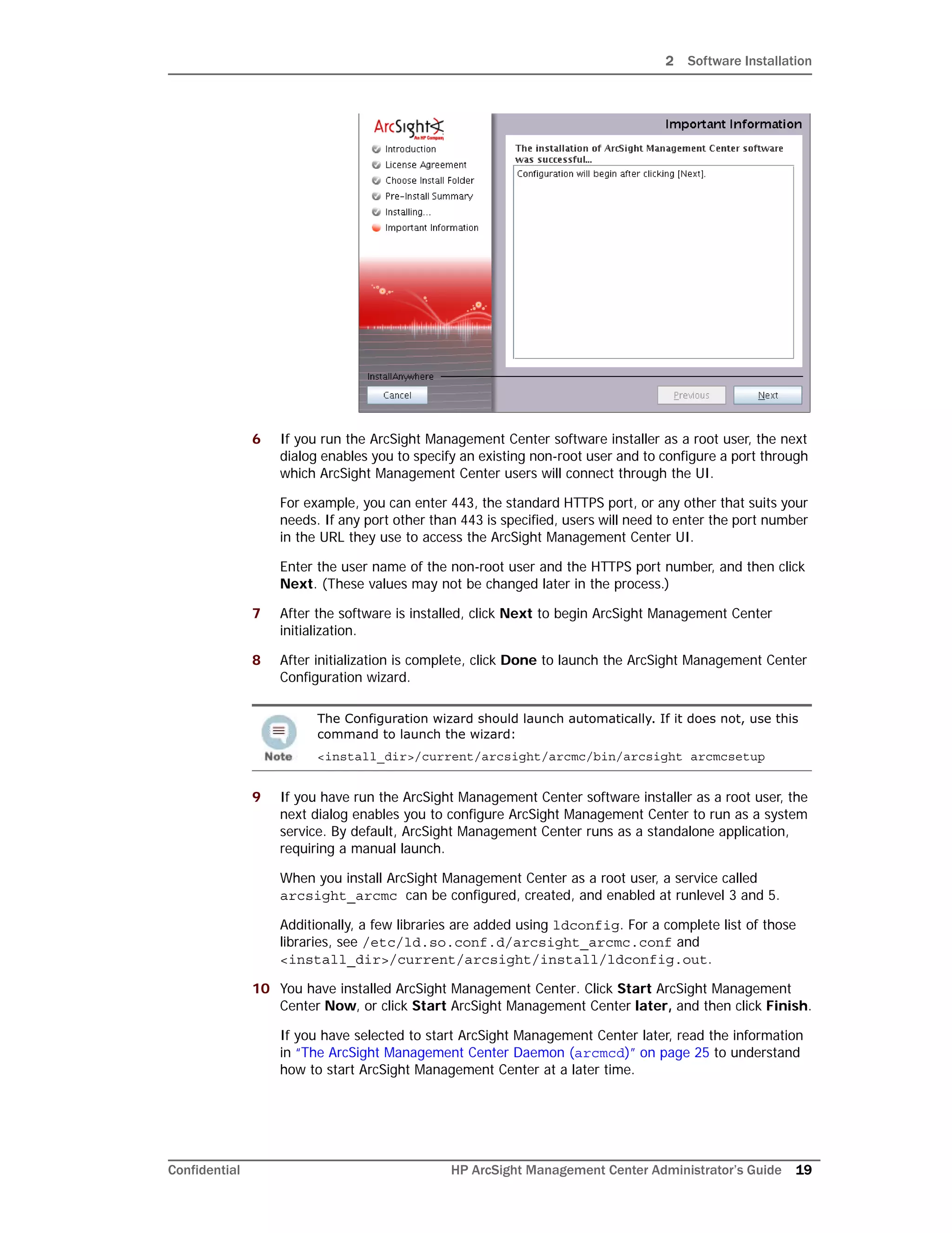
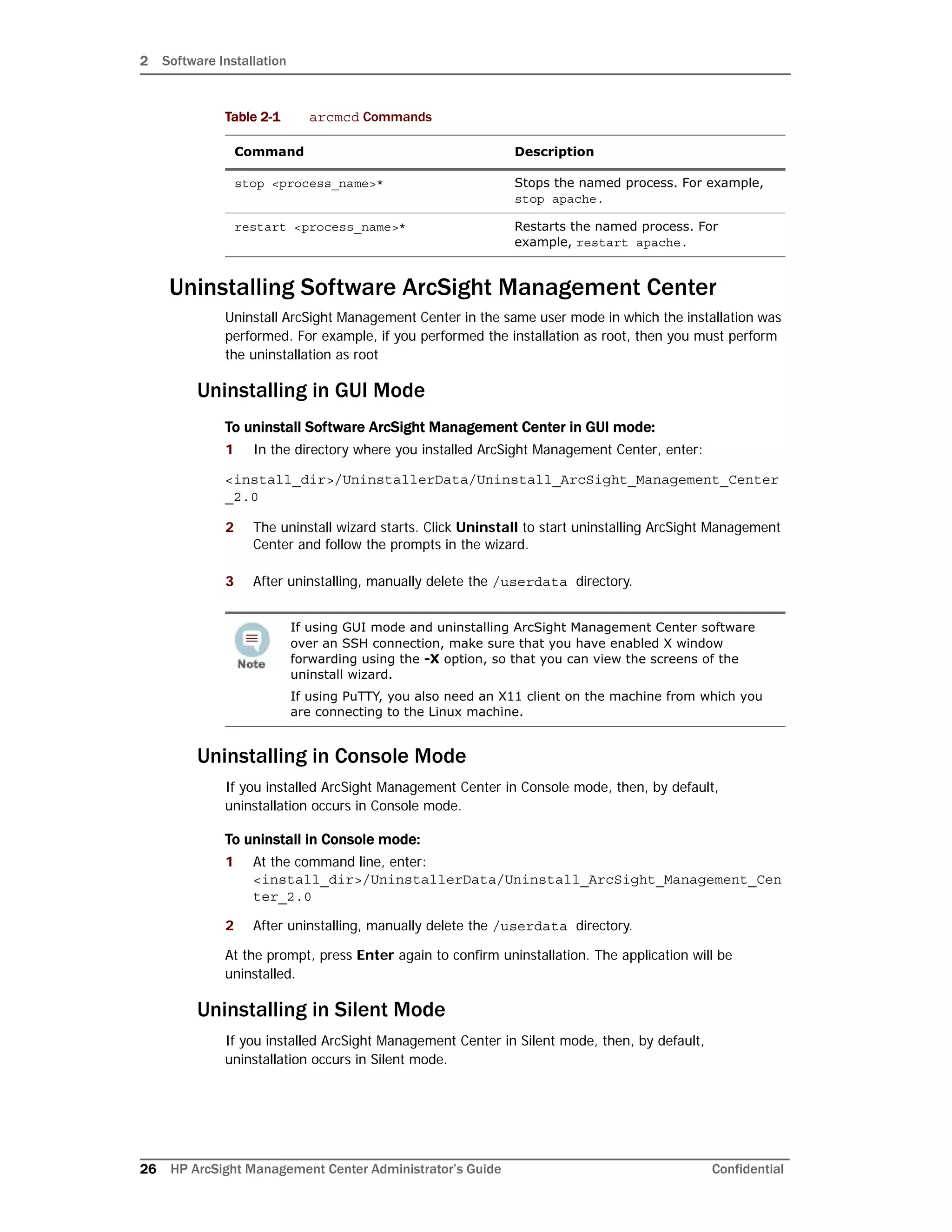
The installation of ArcSight Management Center software was
successful.
Configuration will begin after pressing [Enter].
PRESS <ENTER> TO CONTINUE:
===============================================================
================
Intervention Required
---------------------
Values entered below may not be changed later in the process.
Enter a non-root user account (DEFAULT: ): <non-root user>
Enter an HTTPS port (default is 443) (DEFAULT: 443):
===============================================================
================
Important Information
---------------------
The configuration of ArcSight Management Center software was
successful.
Initialization will begin after pressing [Enter]. This may take
several
minutes.
PRESS <ENTER> TO CONTINUE:
===============================================================
================
Important Information
---------------------
The initialization of ArcSight Management Center software was
successful.
The prompts that follow are the same as the ones described for the GUI mode install in
“GUI Mode Installation” on page 17. Follow the instructions provided for the GUI mode
install to complete the installation.
Silent Mode Installation
Silent mode enables scripting of the installation process. Before you install ArcSight
Management Center in silent mode, create two properties files required for the silent mode
installation:
If ArcSight Management Center is installed in Console mode, it will be
uninstalled in Console mode as well. See “Uninstalling in Console Mode” on
page 26 for more information.](https://image.slidesharecdn.com/arcmcadminguide1-170531062827/75/ArcSight-Management-Center-2-0-Administrator-s-Guide-21-2048.jpg)


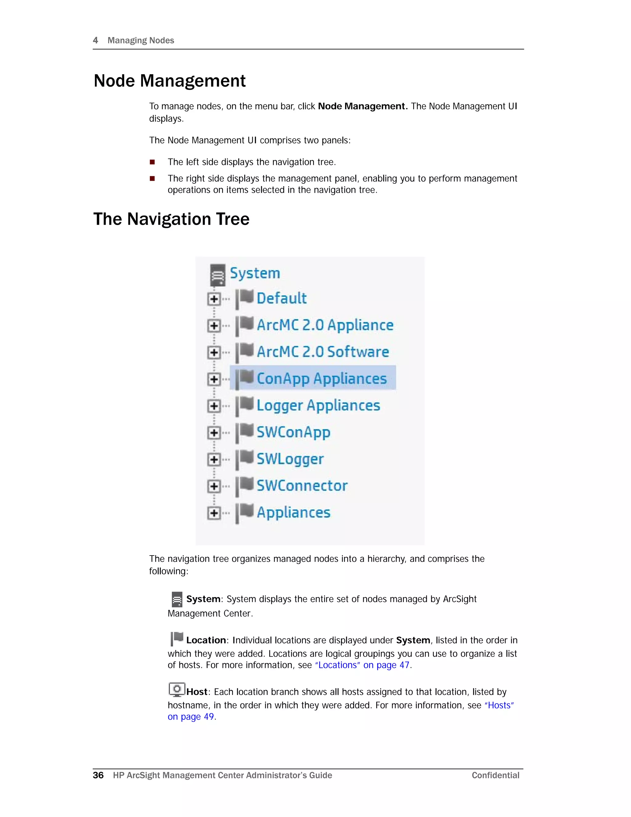
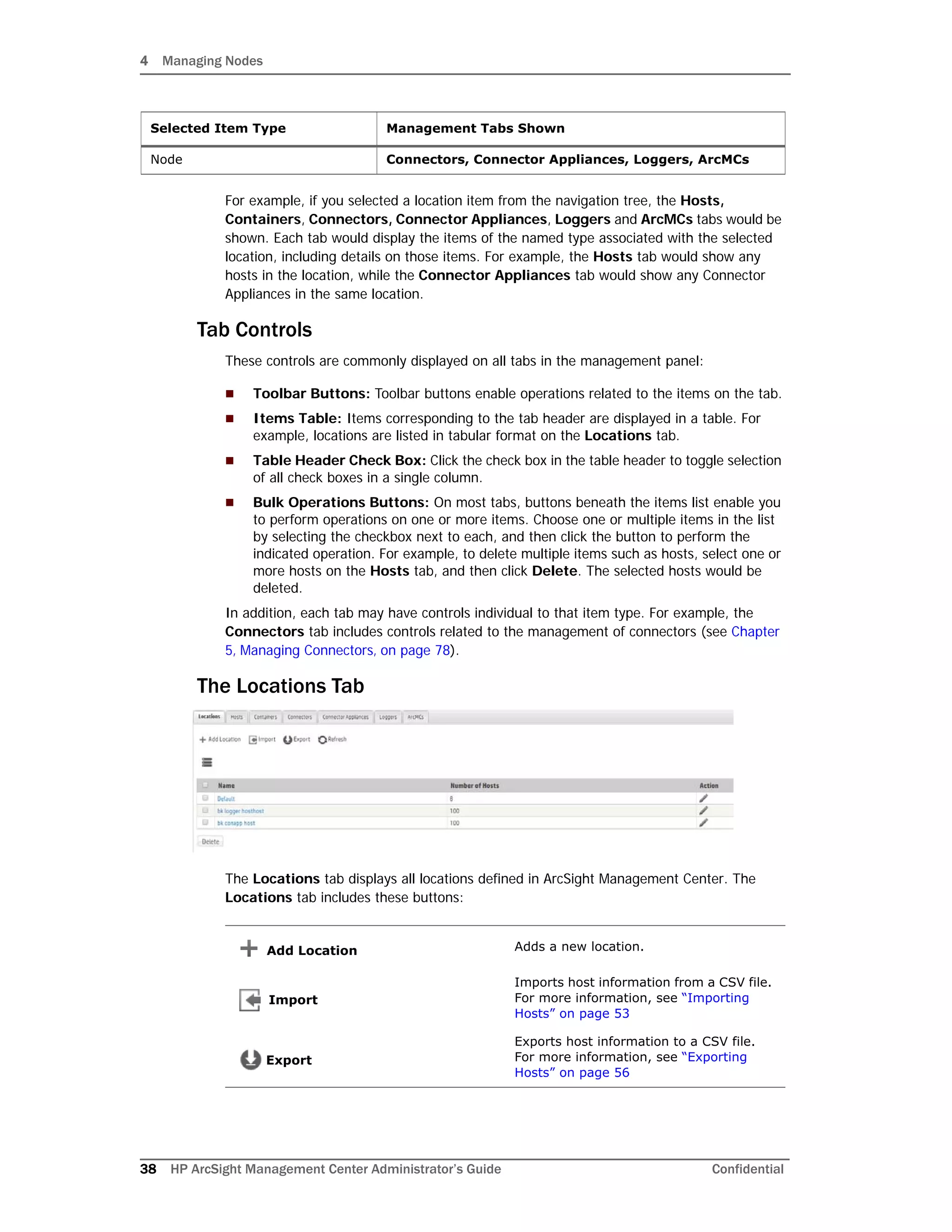
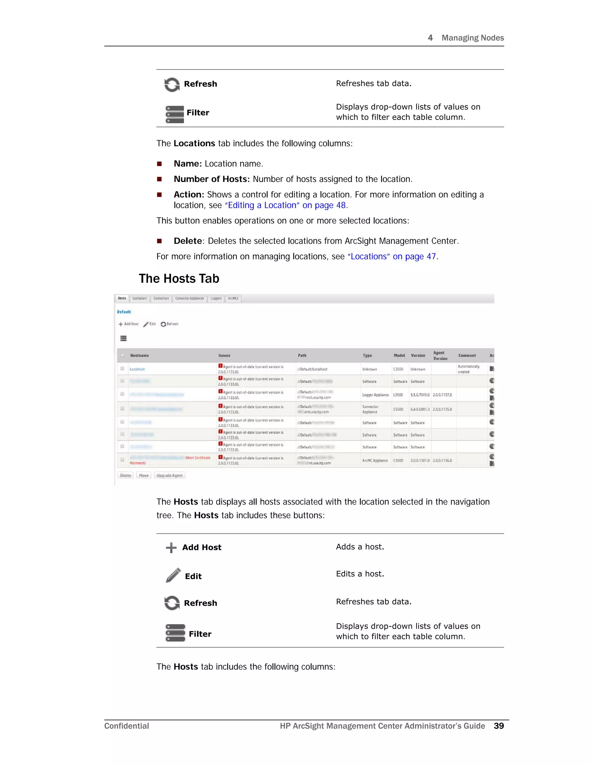
![4 Managing Nodes
56 HP ArcSight Management Center Administrator’s Guide Confidential
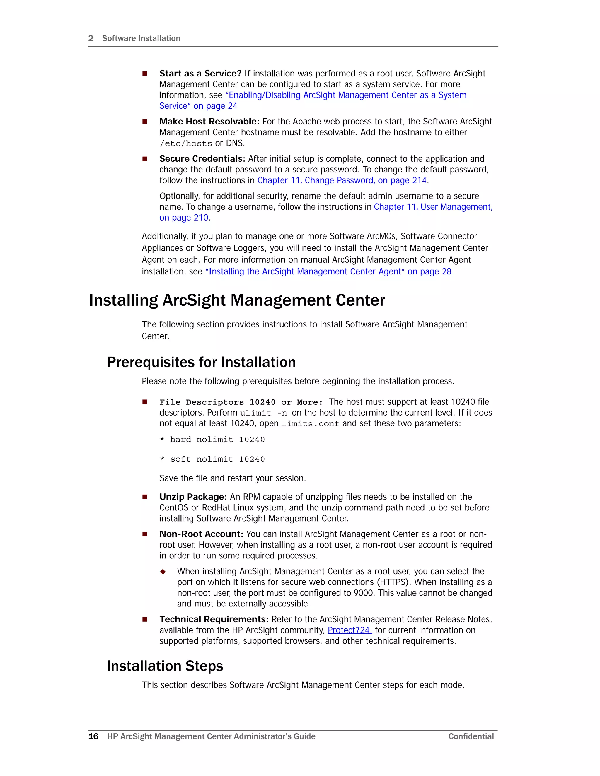
Select Do not import the certificates..., and then click Next if you do not want
to import the certificates. The Upload CSV wizard does not complete the upload
CSV process.
9 The Import Hosts job executes.
Import Hosts Job Logs
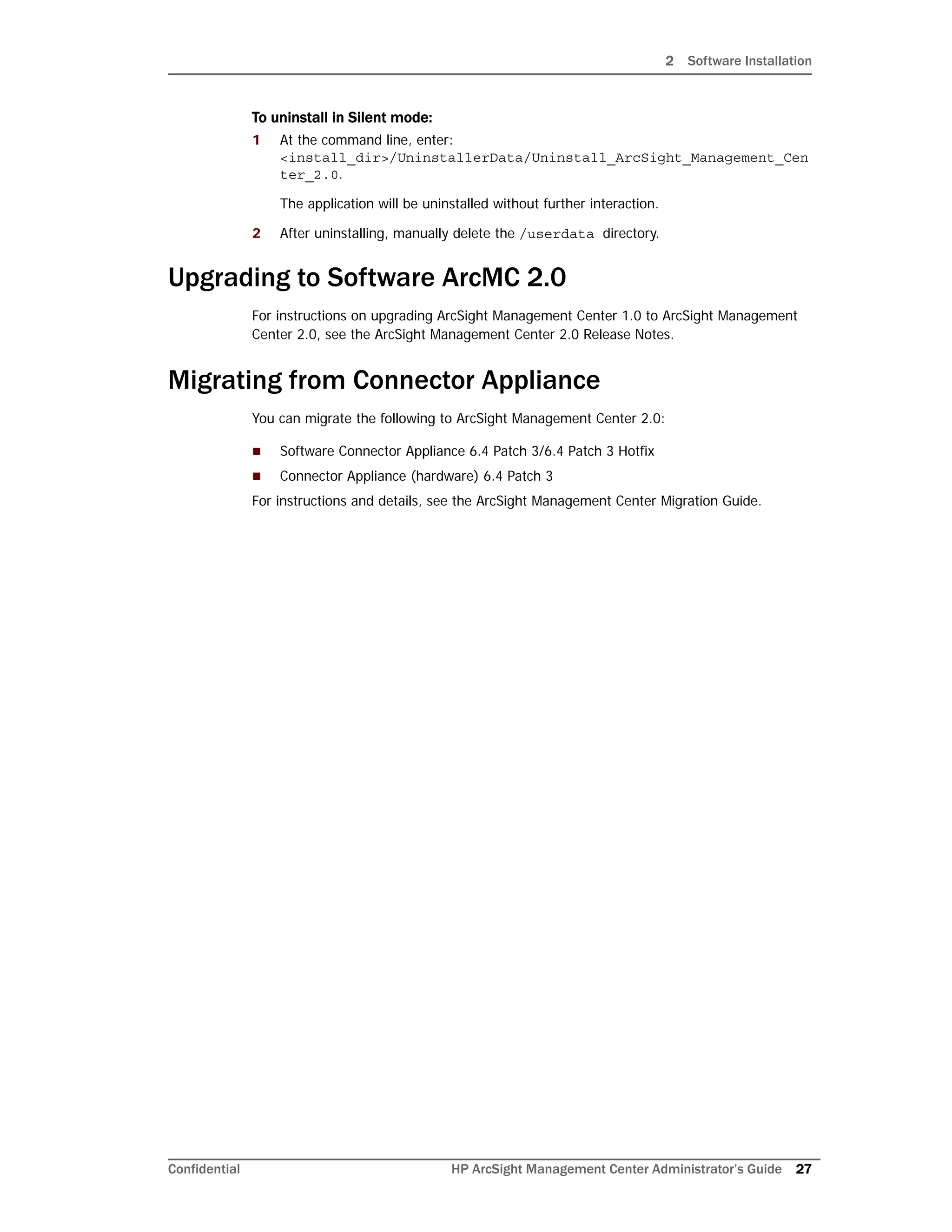
ArcSight Management Center logs the results of all Import Hosts jobs. Each job produces a
new log, named import_hosts_<date>_<time>.txt, where <date> and <time> are
the date and time of the import hosts job.
For Software ArcSight Management Center, logs are located in the directory
<install_dir>/userdata/logs/arcmc/importhosts.
For ArcSight Management Center Appliance, logs are located in the directory
opt/arcsight/userdata/logs/arcmc/importhosts.
Log Format
Each entry in the log will show the success or failure of each host import attempt, in the
format:
<User initiating job>, <CSV filename>, <Time of import host job
start>,<Hostname>,<Success/failure result>
For example:
admin, my_csv_file.csv, Tue Apr 08 14:16:58 PDT 2014,
host.example.com, Host added successfully
If the import hosts job has failed due to one or more invlaid entries in the CSV file, the
result file will show the parsing error details with the line number and error.
For example:
Line [1] has [connector password] field empty. [connector password]
field is required for this host type.
Exporting Hosts
Exporting hosts from an ArcSight Management Center will create a CSV list of hosts
managed by that ArcSight Management Center. (Password information is not included in
this file.)
After adding passwords for each host to the file, you can then import this list of hosts into
another ArcSight Management Center, using the Import Hosts feature described under
“Importing Hosts” on page 53
Exporting hosts is most useful when you are reassigning management of hosts from one
ArcMC to another.
For example, consider two ArcSight Management Centers, called ArcMC East and ArcMC
West. ArcMC East currently manages 50 hosts. However, you are consolidating
management of all hosts to the new ArcMC West. To do this quickly and easily, you would
export the hosts from ArcMC East into a CSV file. Then, after adding in password data for
The Import Hosts wizard does not complete the upload if certificate upload
failed for any of the connectors in a container, or if any of the certificates
failed to import into the trust store.](https://image.slidesharecdn.com/arcmcadminguide1-170531062827/75/ArcSight-Management-Center-2-0-Administrator-s-Guide-56-2048.jpg)


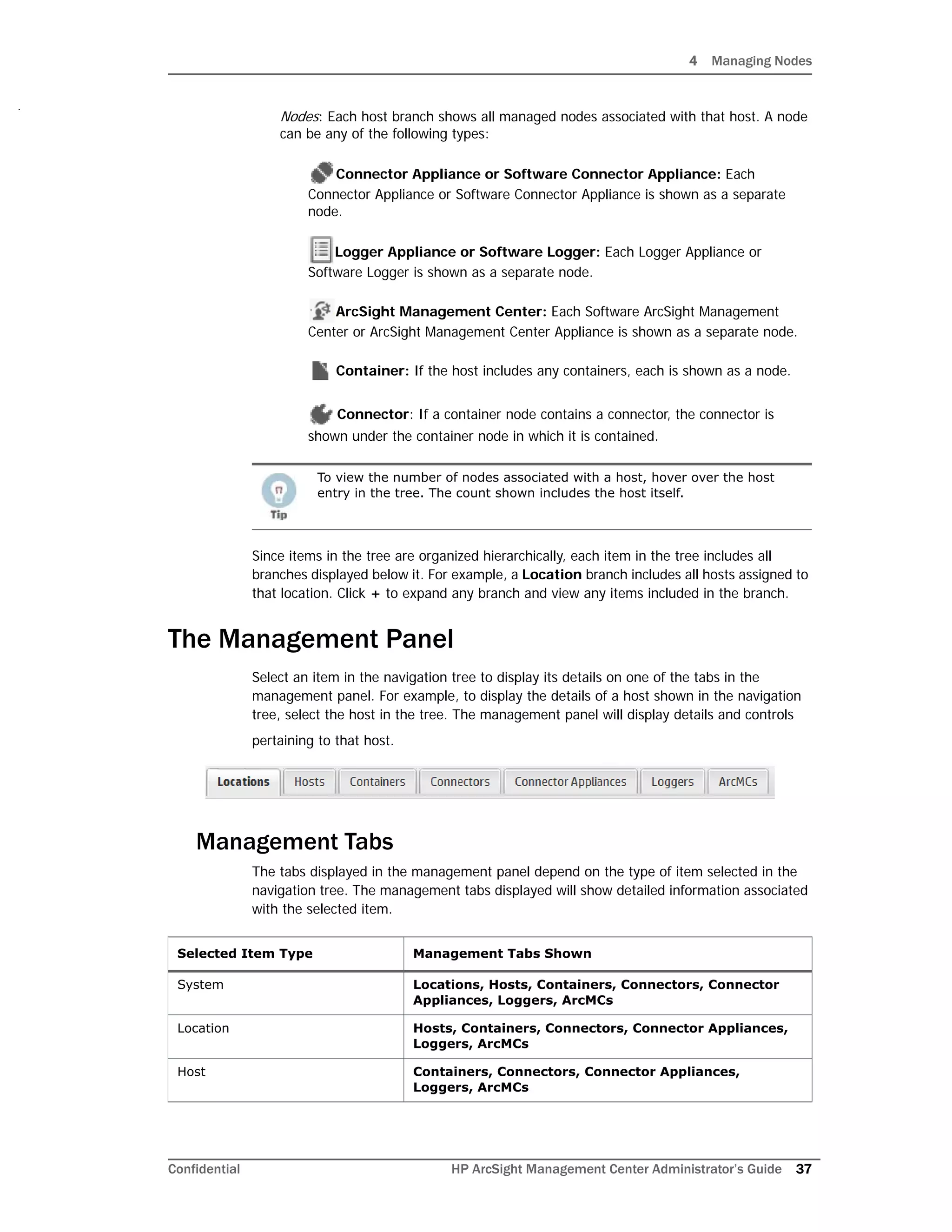
![5 Managing HP ArcSight Products
Confidential HP ArcSight Management Center Administrator’s Guide 101
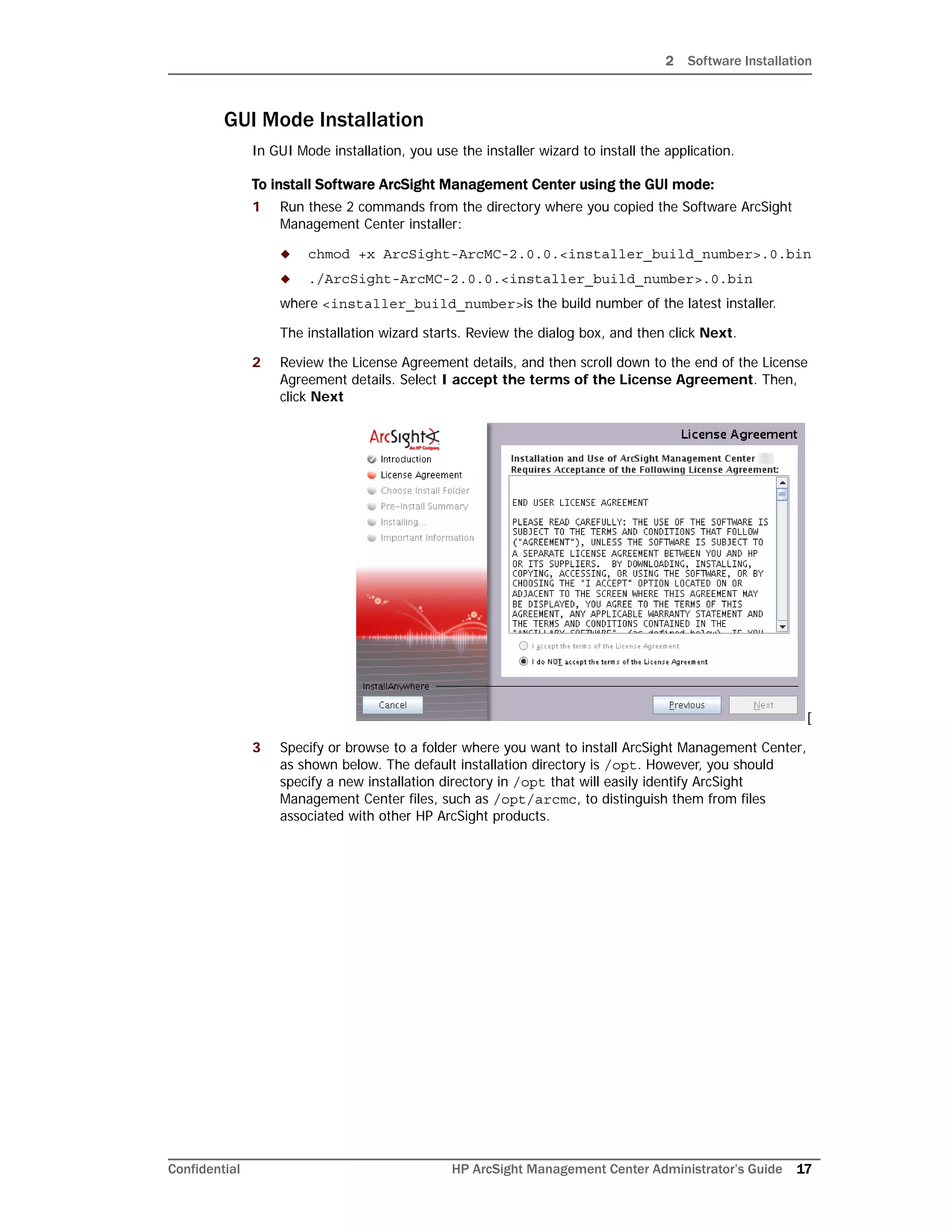
On Connector Appliance
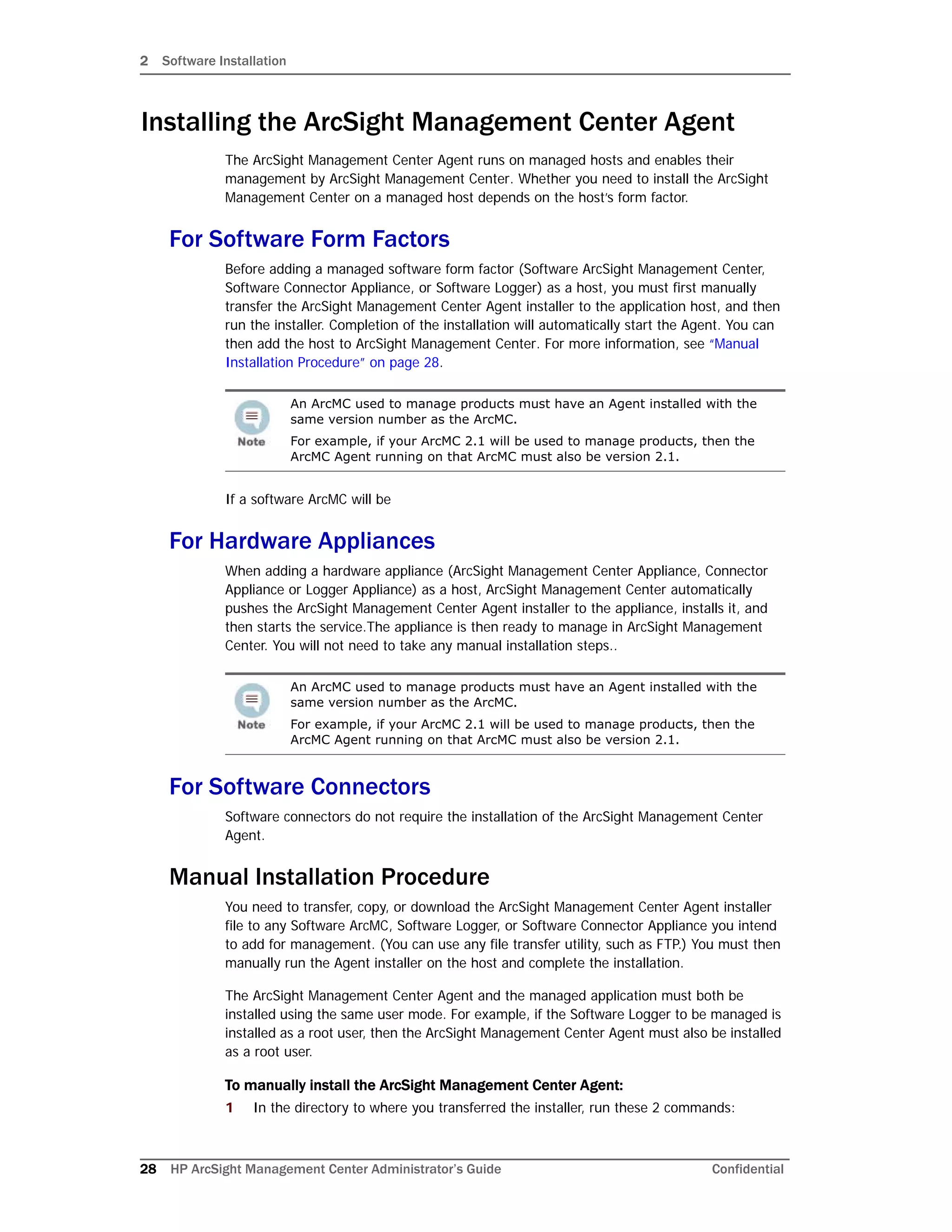
4 Add a Check Point connector by following instructions described in “Adding a
Connector” on page 79. You need to provide the following information.
5 An error similar to the following is displayed.
-1:[X] Unable to connect to the Lea Server[10.0.101.185] -1:1
connection test failed!
Select the Ignore warnings check box, and then click Next.
6 Continue to configure the rest of the connector. Go to Step 9 in “Adding a Connector”
on page 79.
Adding the MS SQL Server JDBC Driver
When you install and configure database connectors that use Microsoft SQL Server as the
database, a JDBC driver is required. This driver does not ship pre-installed; you need to
install it before configuring database connectors on the appliance.
To install a JDBC Driver:
1 From the Microsoft web site, download the MS SQL Server JDBC Driver to a computer
that can access ArcSight Management Center.
2 Run the setup program to install the driver.
3 Follow the instructions in “Uploading Files to a Repository” on page 91 to add the
sqljdbc.jar file.
The new driver file is added to the repository, as shown in the following example.
After you have installed the JDBC driver, you need to upload the driver file to the
containers that will contain the SQL Server database Connectors. Follow the
instructions in “Uploading a File from the Repository” on page 93.
After the driver file has been uploaded to a container, follow the instructions in “Adding
a Connector” on page 79 to add a connector that requires a JDBC driver.
Parameters Values to input
Type Check Point FW-1/VPN-1 OPSEC NG
Connection
Type
SSLCA
Connector
Table
Parameters
Server IP: The IP address of the Check Point server.
Server Port: The port on the server that listens for SSLCA
connections. Use the default value 18184.
OPSEC SIC Name: The name you noted in Step 1.
OPSEC SSLCA File: The name you noted after pulling the
certificate in Step 2.
OPSEC Entity SIC Name: The name you noted in Step 1.
The name of the jar file may be different from that of some JDBC driver
versions. Different versions of the JDBC driver are required for different SQL
Server database versions; be sure to use the correct driver for your
database.](https://image.slidesharecdn.com/arcmcadminguide1-170531062827/75/ArcSight-Management-Center-2-0-Administrator-s-Guide-101-2048.jpg)
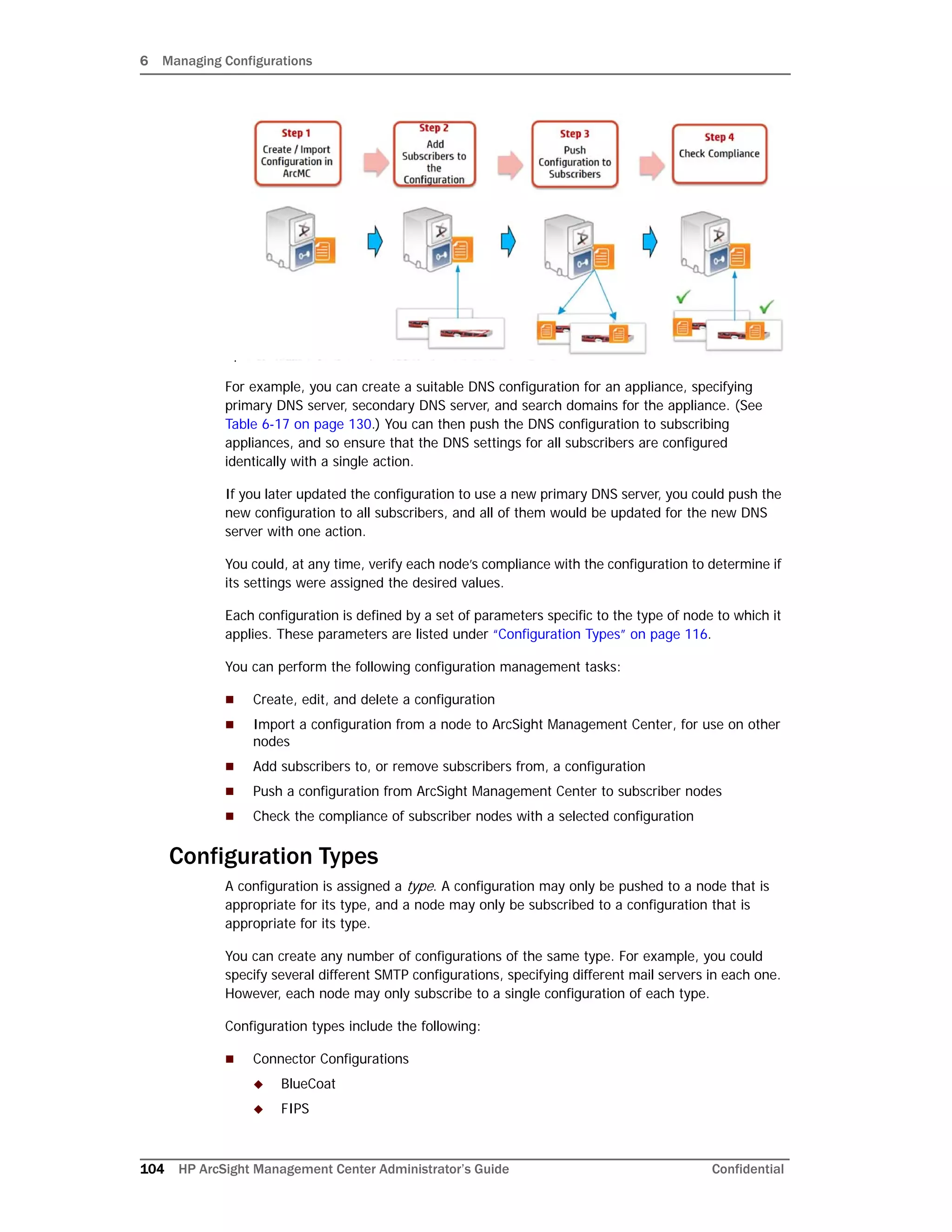
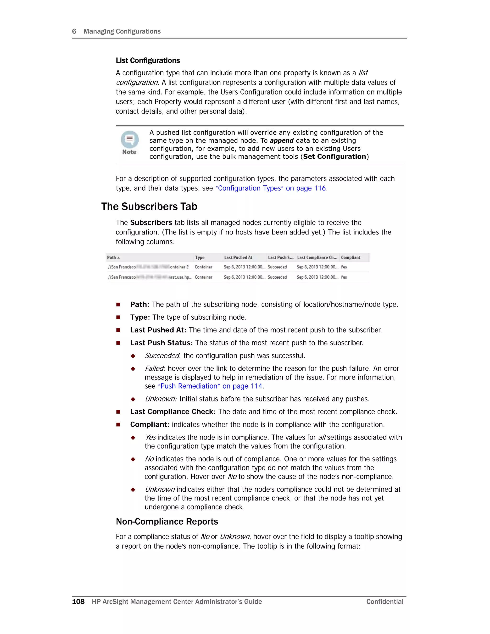
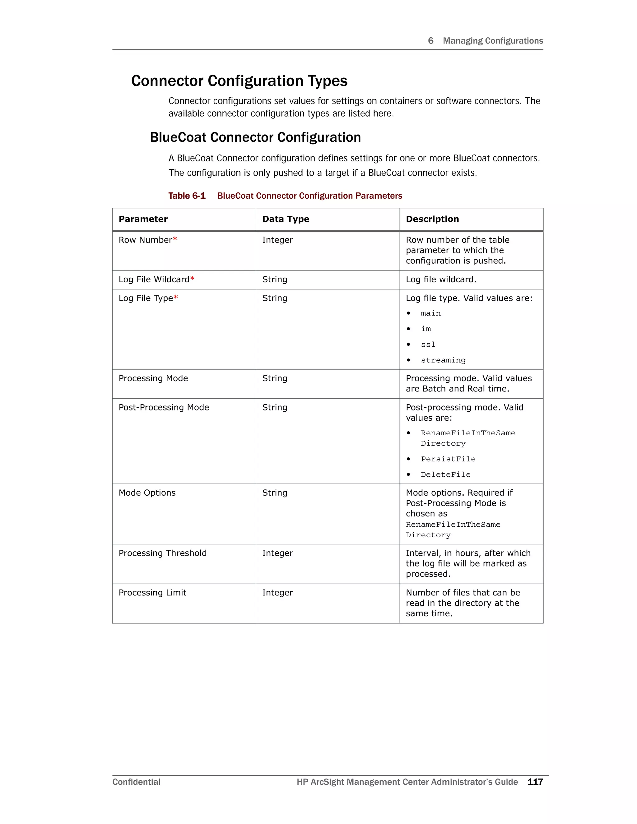
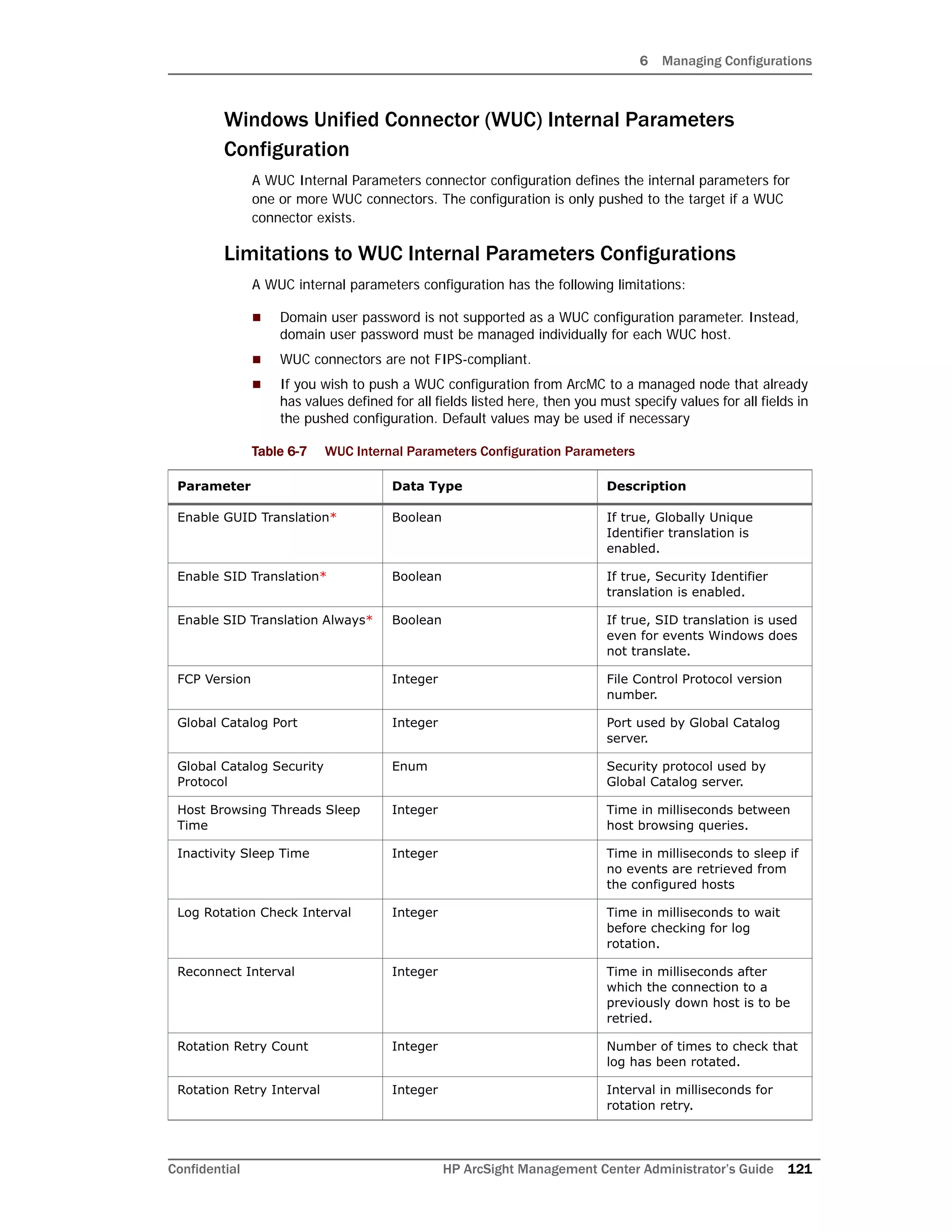
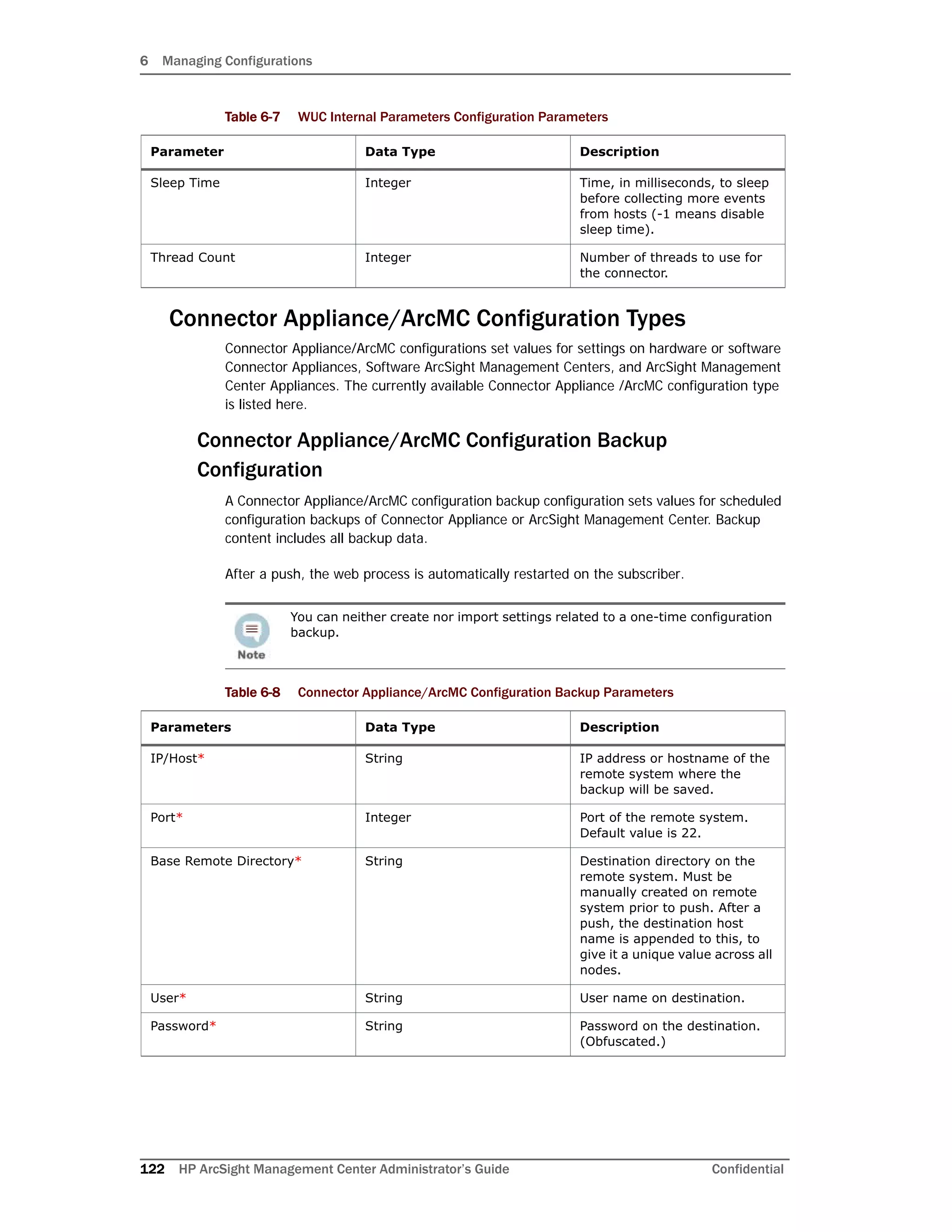
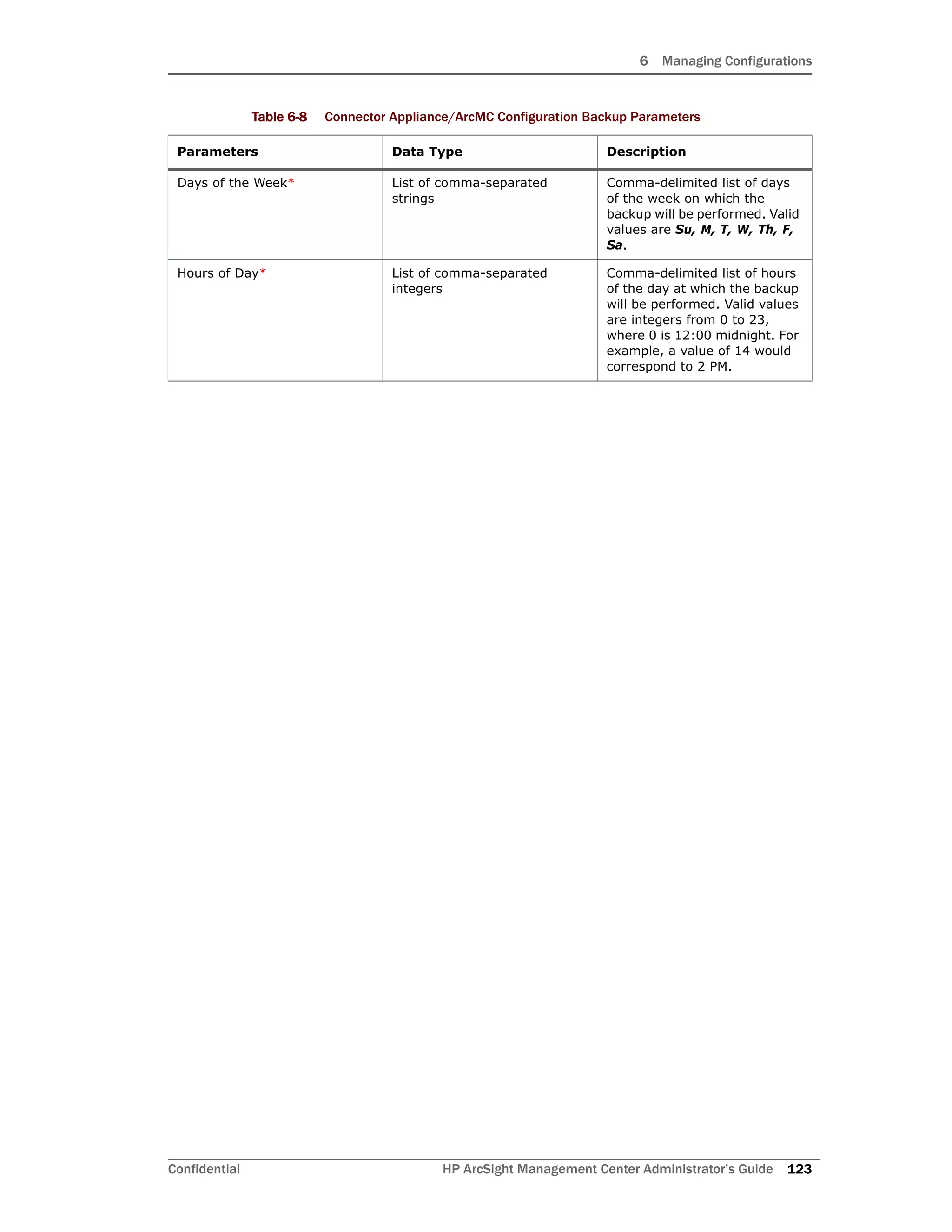
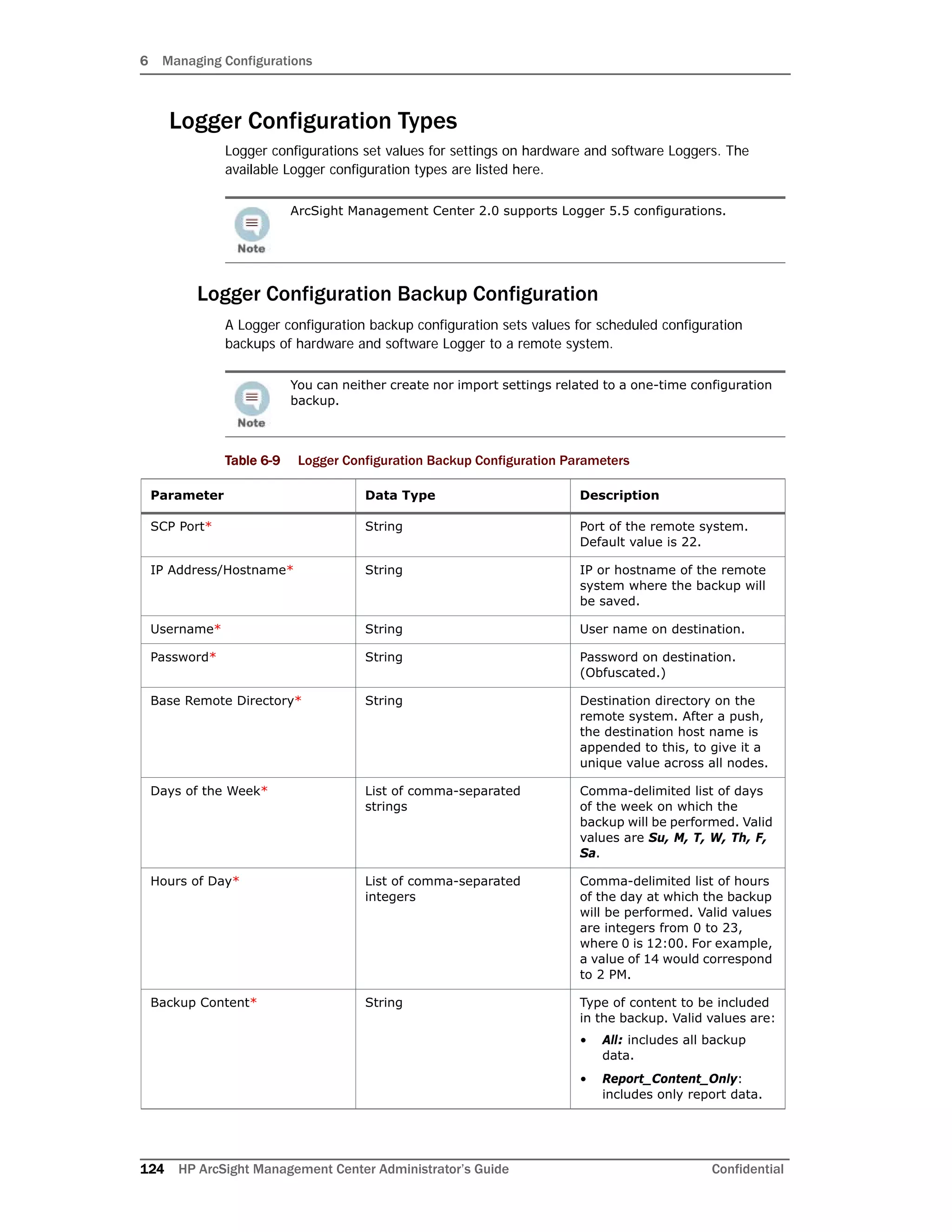
![6 Managing Configurations
Confidential HP ArcSight Management Center Administrator’s Guide 109
setting_name1:<configuration value>:<node
value>|setting_name2:<configuration value>:<node value>|...
where setting_nameN is each differing setting in the configuration, <configuration
value> is the setting’s value in the configuration in ArcSight Management Center, and
<node value> is the setting’s value on the non-compliant node. Each problematic setting
and its values are separated by a pipe character (|).
If the property type is a list, then the list value will be enclosed in a pair of square brackets;
for example, [item1, item2].
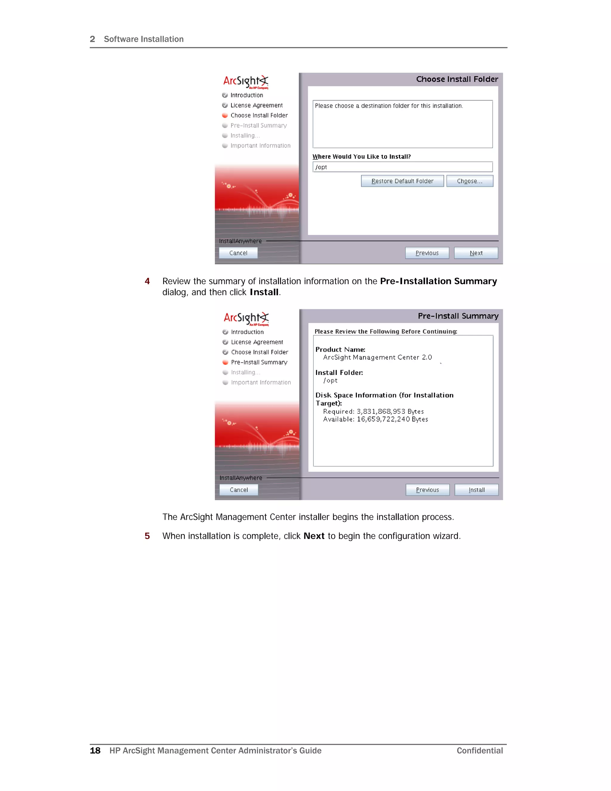
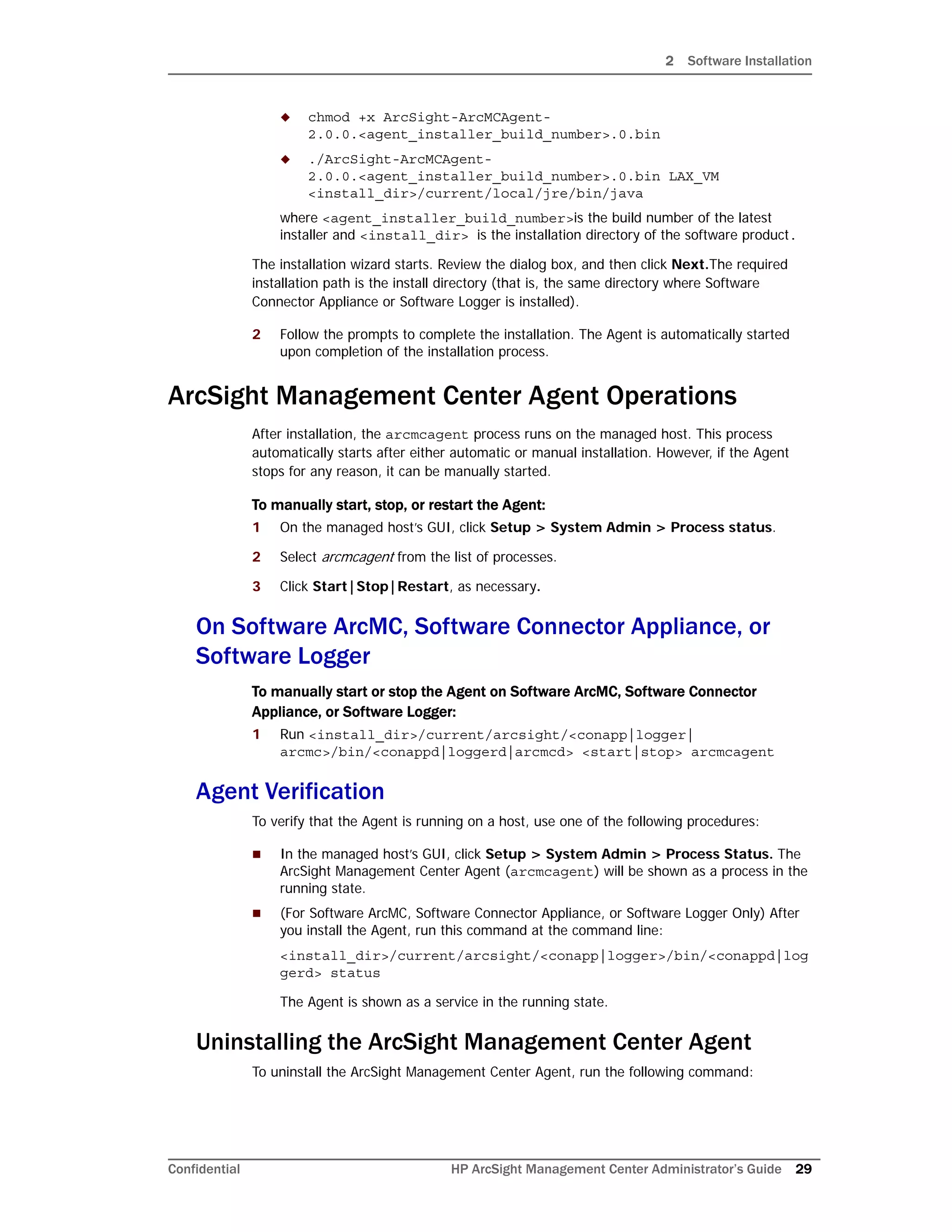
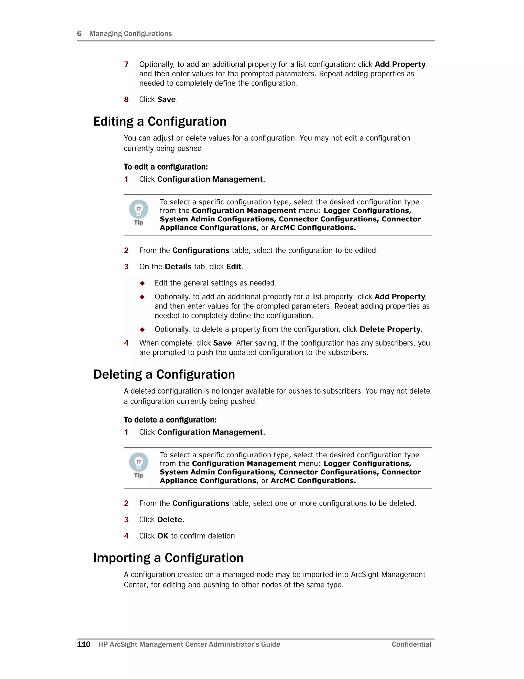
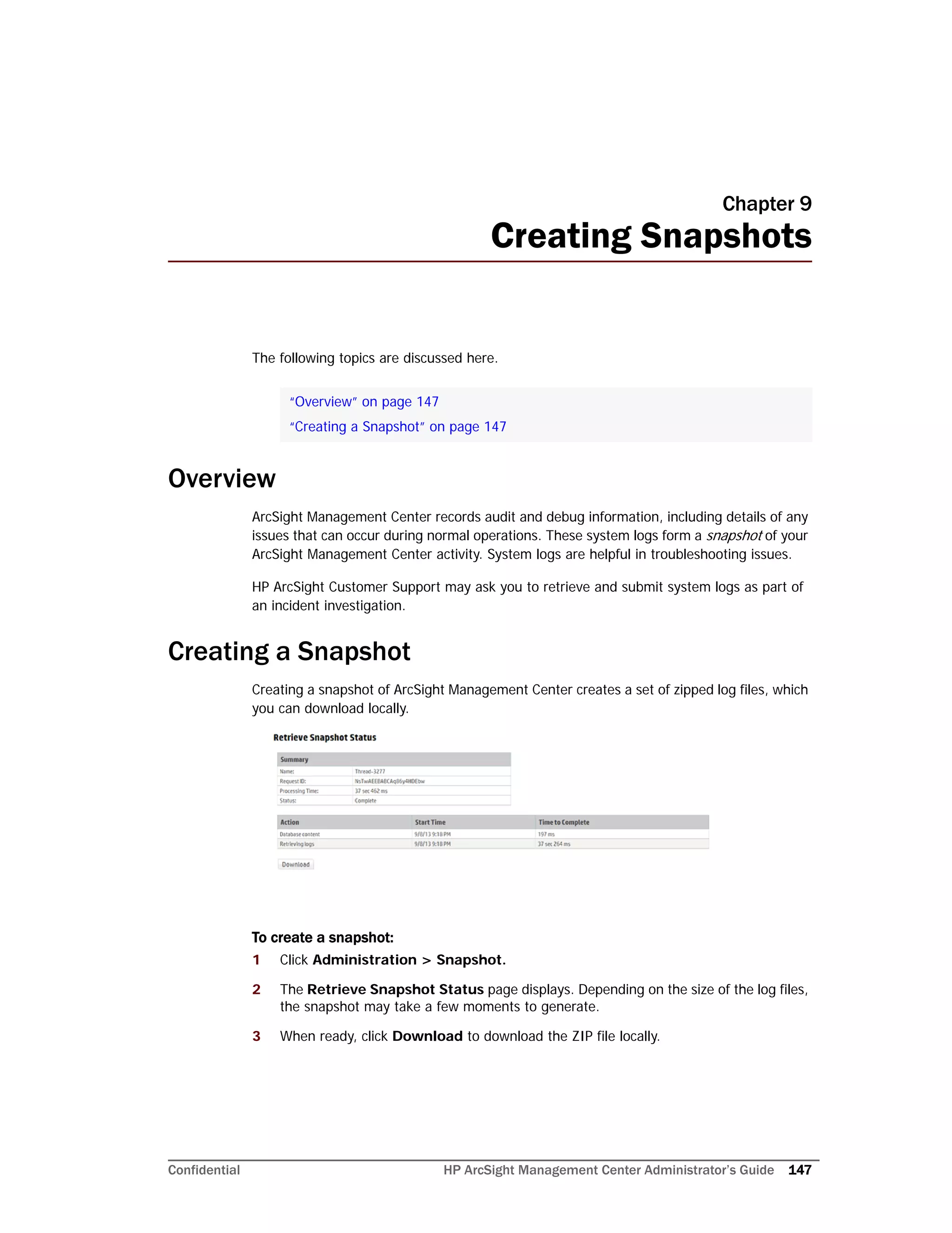
Creating a Configuration
You can create a configuration for pushing to any subscribed nodes.
To create a configuration:
1 Click Configuration Management.
2 Under Configurations, click New.
3 On the Details tab, select a configuration type from the Configuration Type
drop-down list. (Only the configuration types appropriate for the node type are shown
in the drop-down list.)
4 In Configuration Name, enter a name for the configuration. (Configuration names
must be unique and may be up to 255 characters in length.)
5 Enter values for any required parameters, which are indicated with a red asterisk (*).
6 Optionally, add values for any optional parameters.
Although an ArcSight Management Center can manage other ArcSight
Management Centers, each can have its own, independent set of
configurations.
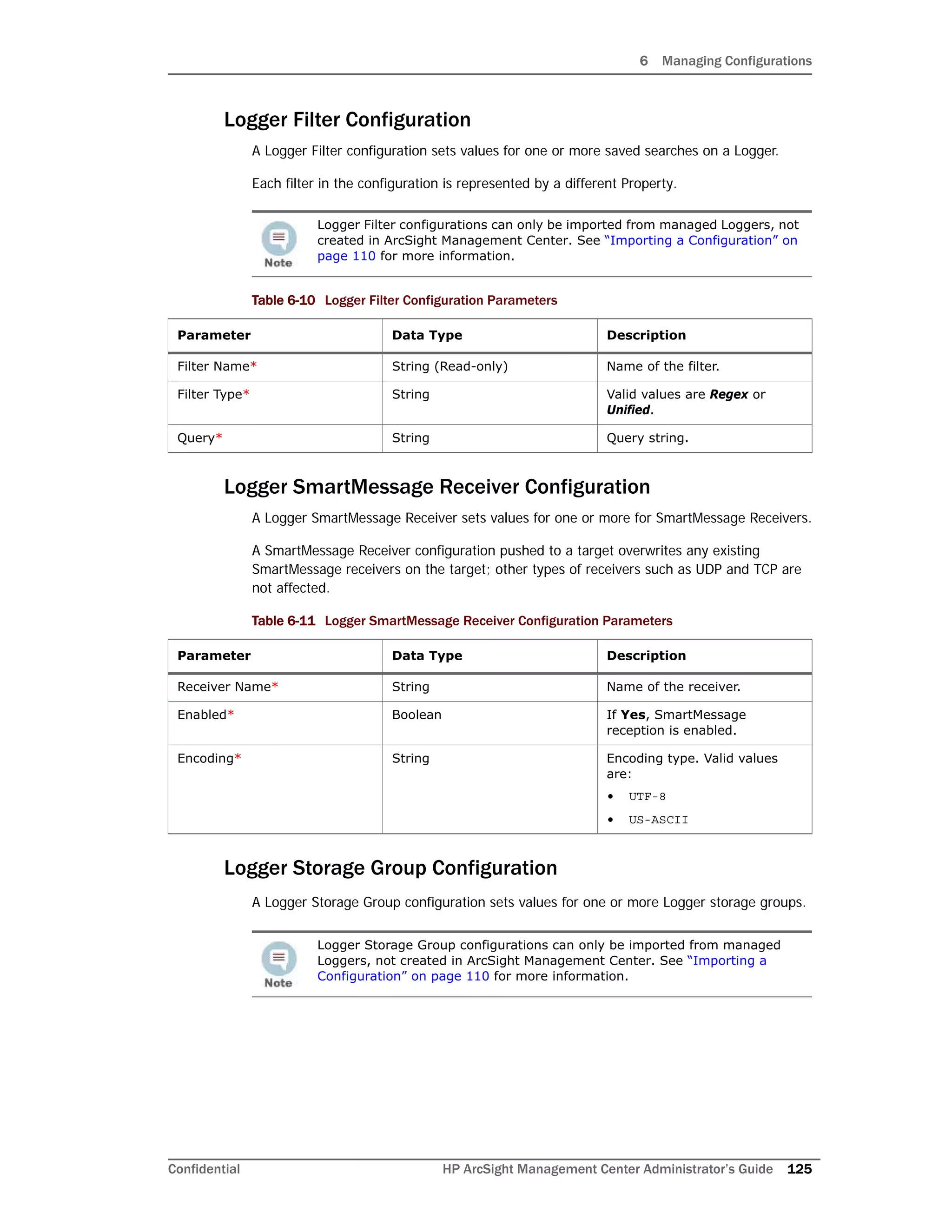
The following configuration types can only be imported from managed nodes,
but cannot be created in ArcSight Management Center:
• Logger Storage Group
• Logger Filter
• Authentication External
• Users
For more information on importing a configuration from a managed node, see
“Importing a Configuration” on page 110.
To select a specific configuration type, select the desired configuration type
from the Configuration Management menu: Logger Configurations,
System Admin Configurations, Connector Configurations, Connector
Appliance Configurations, or ArcMC Configurations.
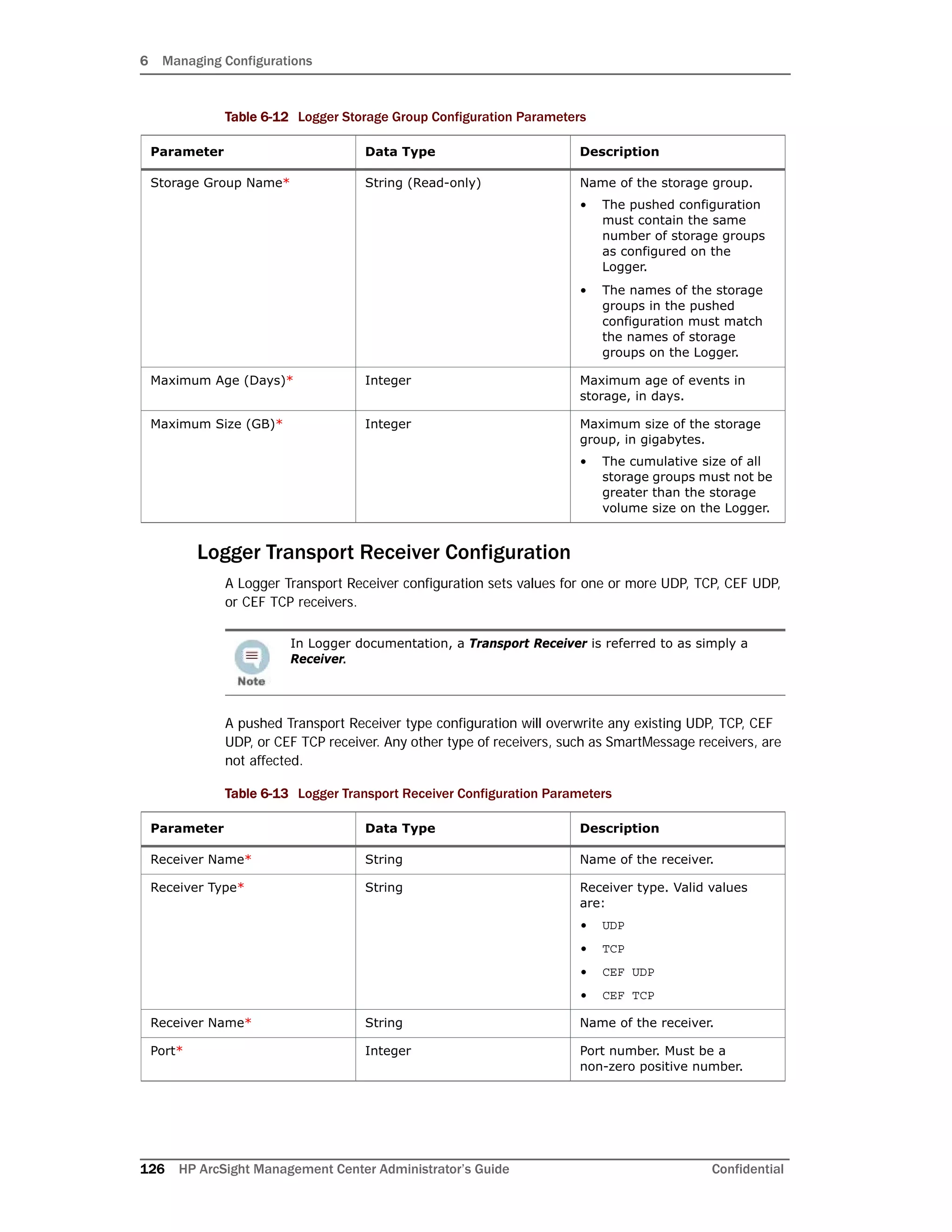
For a description of valid parameters for each configuration type, and the
data type associated with each, see “Configuration Types” on page 116.](https://image.slidesharecdn.com/arcmcadminguide1-170531062827/75/ArcSight-Management-Center-2-0-Administrator-s-Guide-109-2048.jpg)
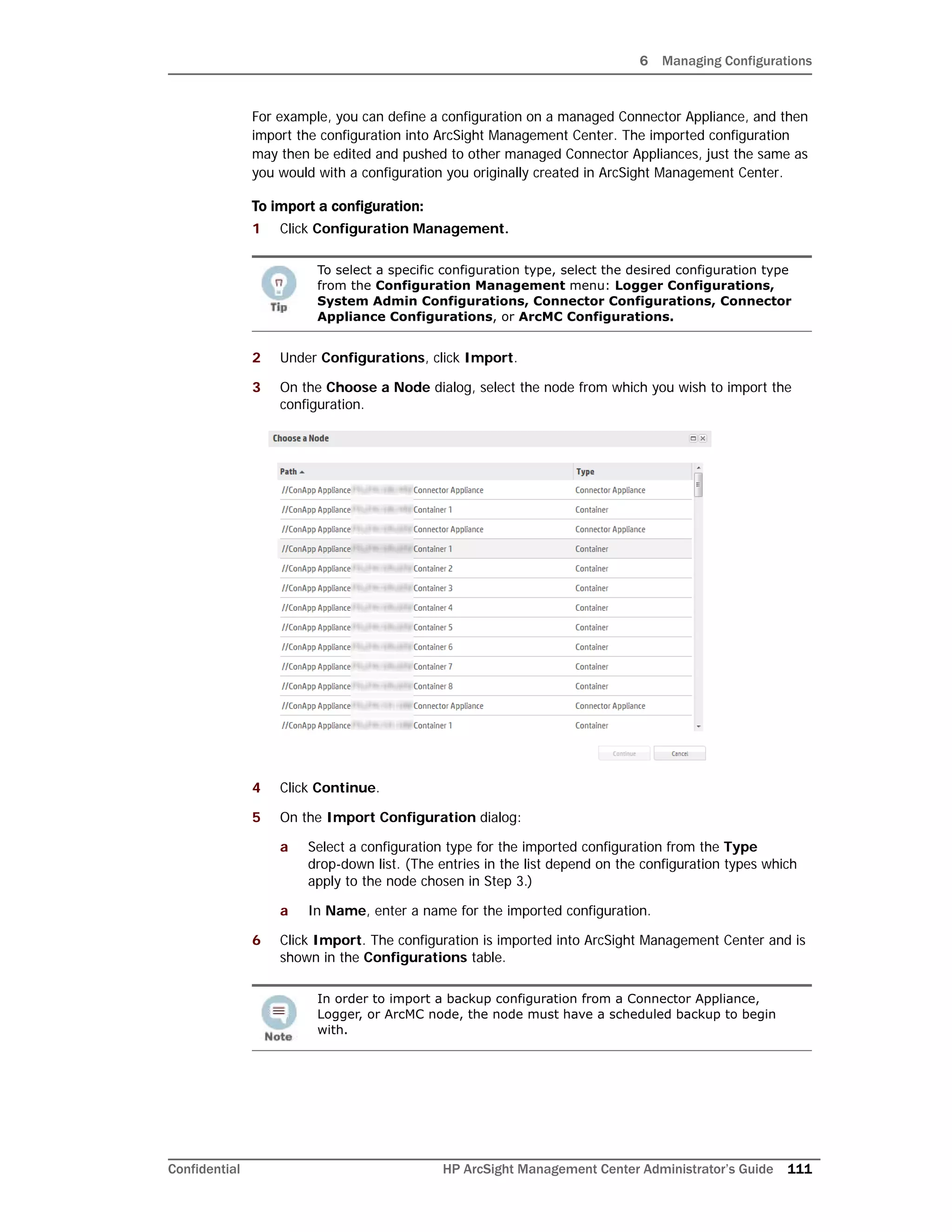
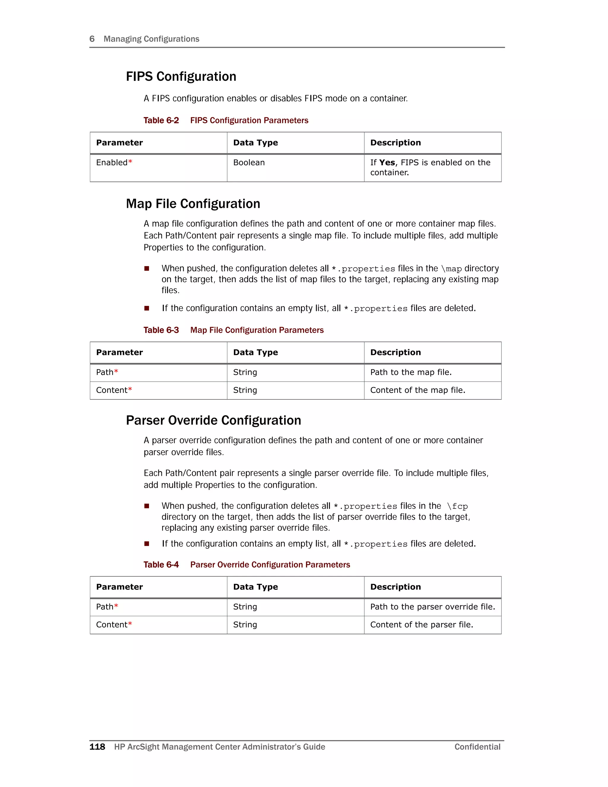
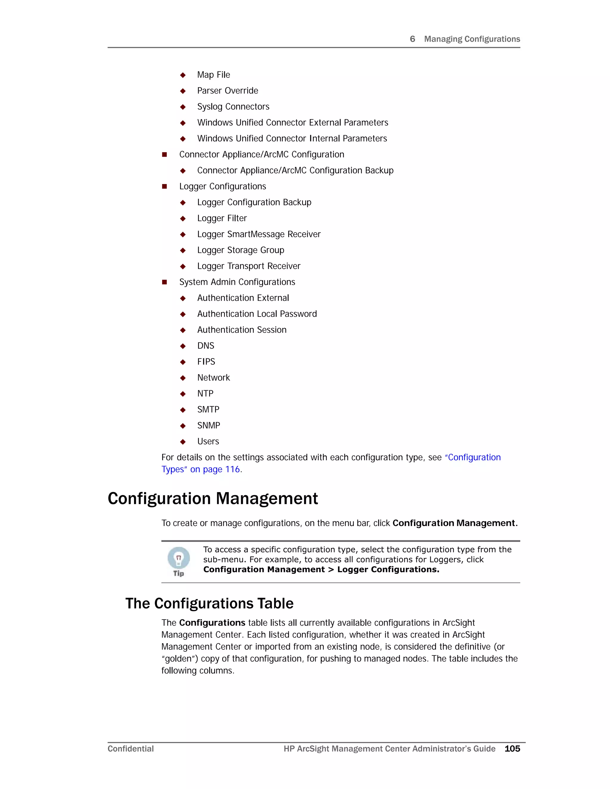
![6 Managing Configurations
128 HP ArcSight Management Center Administrator’s Guide Confidential
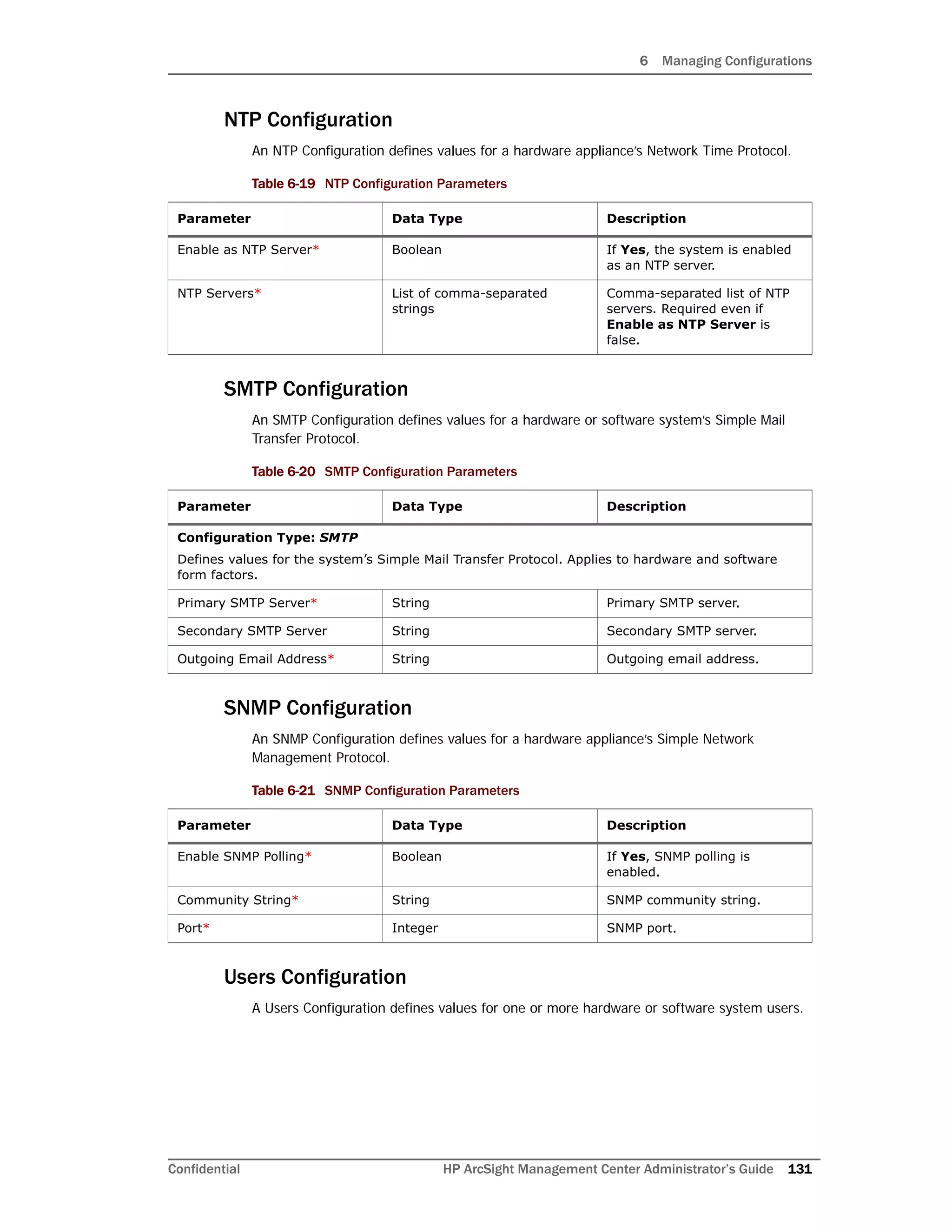
System Admin Configuration Types
System Admin configurations set values for system administrative settings. The available
System Admin configuration types are listed here.
Authentication External
An Authentication External configuration defines values and behavior for a hardware or
software system requiring authentication to an external server, such as LDAP or RADIUS.
After changing the Authentication Method on a host, you must delete the host from
ArcSight Management Center, and then re-add it using Node Management.
Authentication External configurations can only be imported from managed
Loggers, not created in ArcSight Management Center. See “Importing a
Configuration” on page 110 for more information.
Table 6-14 Authentication External Configuration Parameters
Parameter Data Type Description
Authentication Method* String System authentication method.
Allow Local Password Fallback
for Default Admin Only*
Boolean If Yes, the authentication
server will fall back to local
passwords for authentication
for administrators.
Allow Local Password Fallback
for All Users*
Boolean If Yes, the authentication
server will fall back to local
passwords for authentication
for all users.
LDAP Server Hostname[port]* String LDAP server hostname and
port.
LDAP Backup Server Hostname
[port]
String LDAP backup server hostname
and port.
LDAP Server Request Timeout
(seconds)
Integer LDAP server request timeout,
in seconds.
RADIUS Server
Hostname[port]
String RADIUS server hostname and
port.
RADIUS Backup Server
Hostname[port]
String RADIUS backup server
hostname and port
RADIUS Shared Authentication
Secret
String RADIUS authentication shared
secret.
RADIUS Server NAS IP Address String RADIUS server Network Access
Server IP address.
RADIUS Request Timeout
(seconds)
Integer RADIUS server request
timeout, in seconds.
RADIUS Retry Request Integer Number of times to retry
RADIUS server requests.
RADIUS Protocol String Type of RADIUS protocol.](https://image.slidesharecdn.com/arcmcadminguide1-170531062827/75/ArcSight-Management-Center-2-0-Administrator-s-Guide-128-2048.jpg)
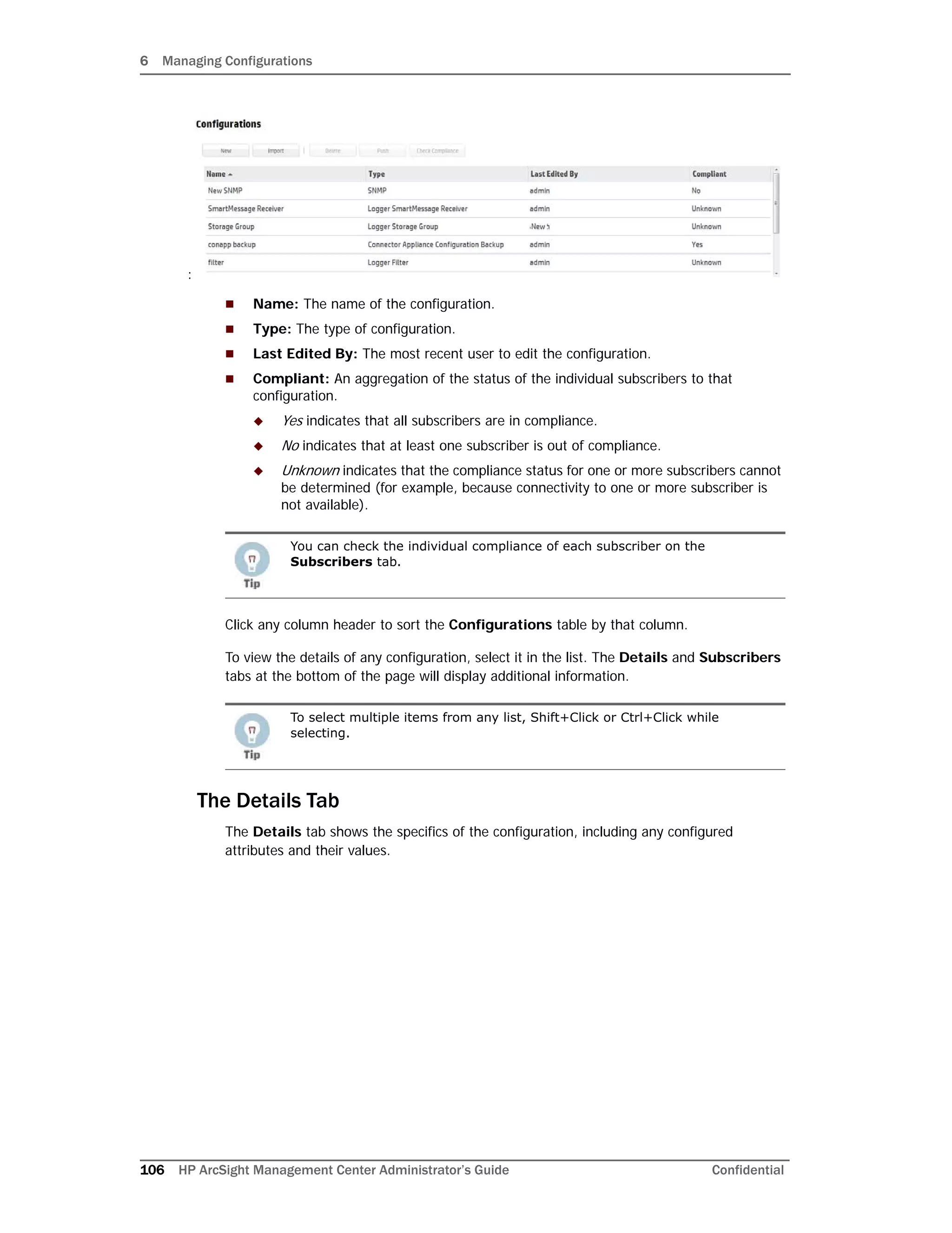
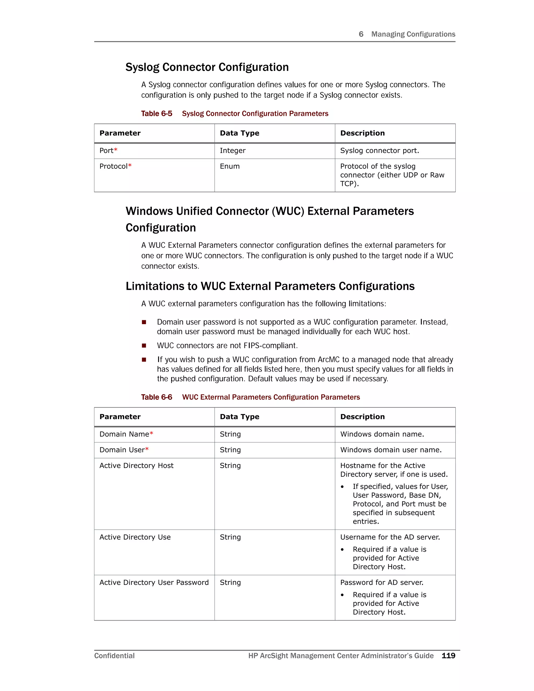
![6 Managing Configurations
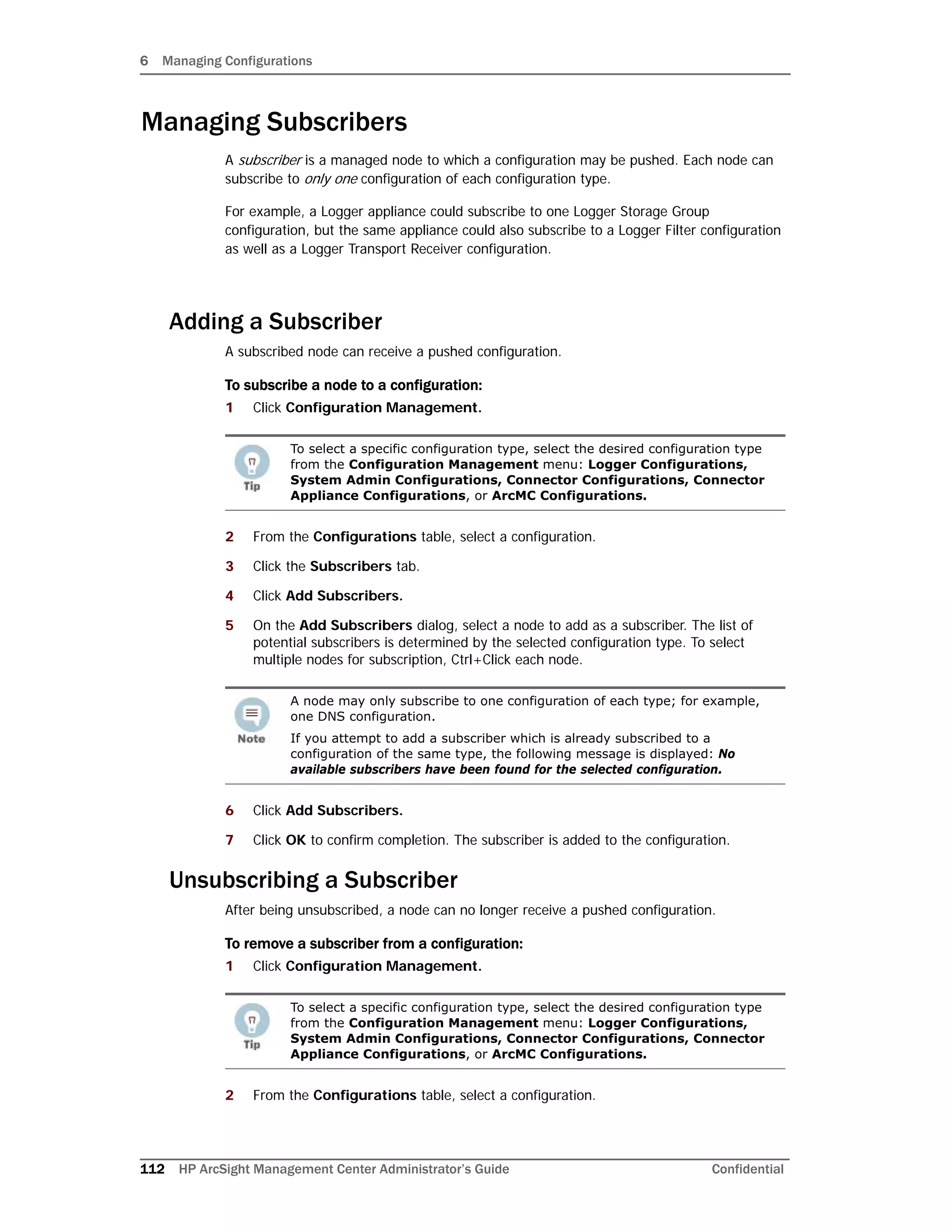
Confidential HP ArcSight Management Center Administrator’s Guide 129
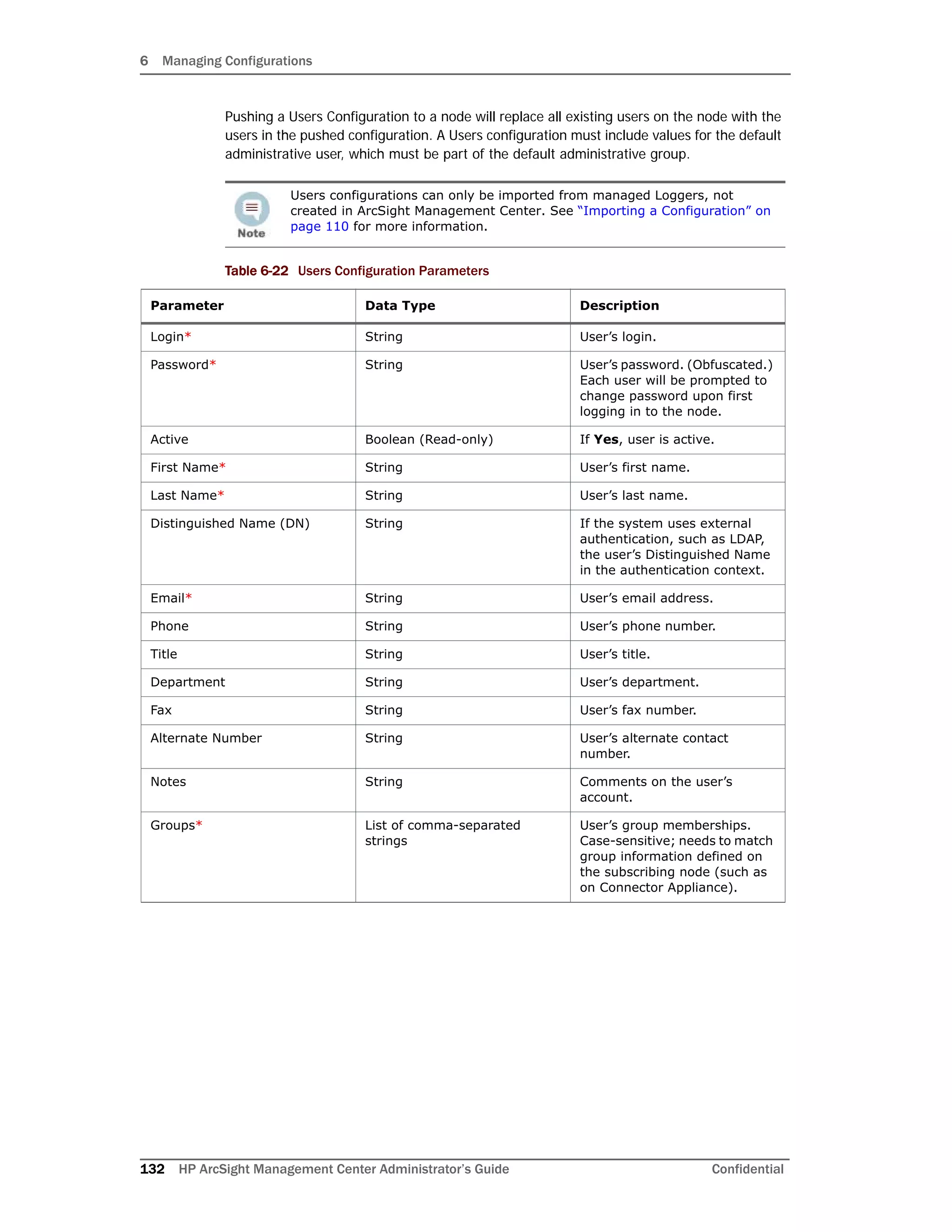
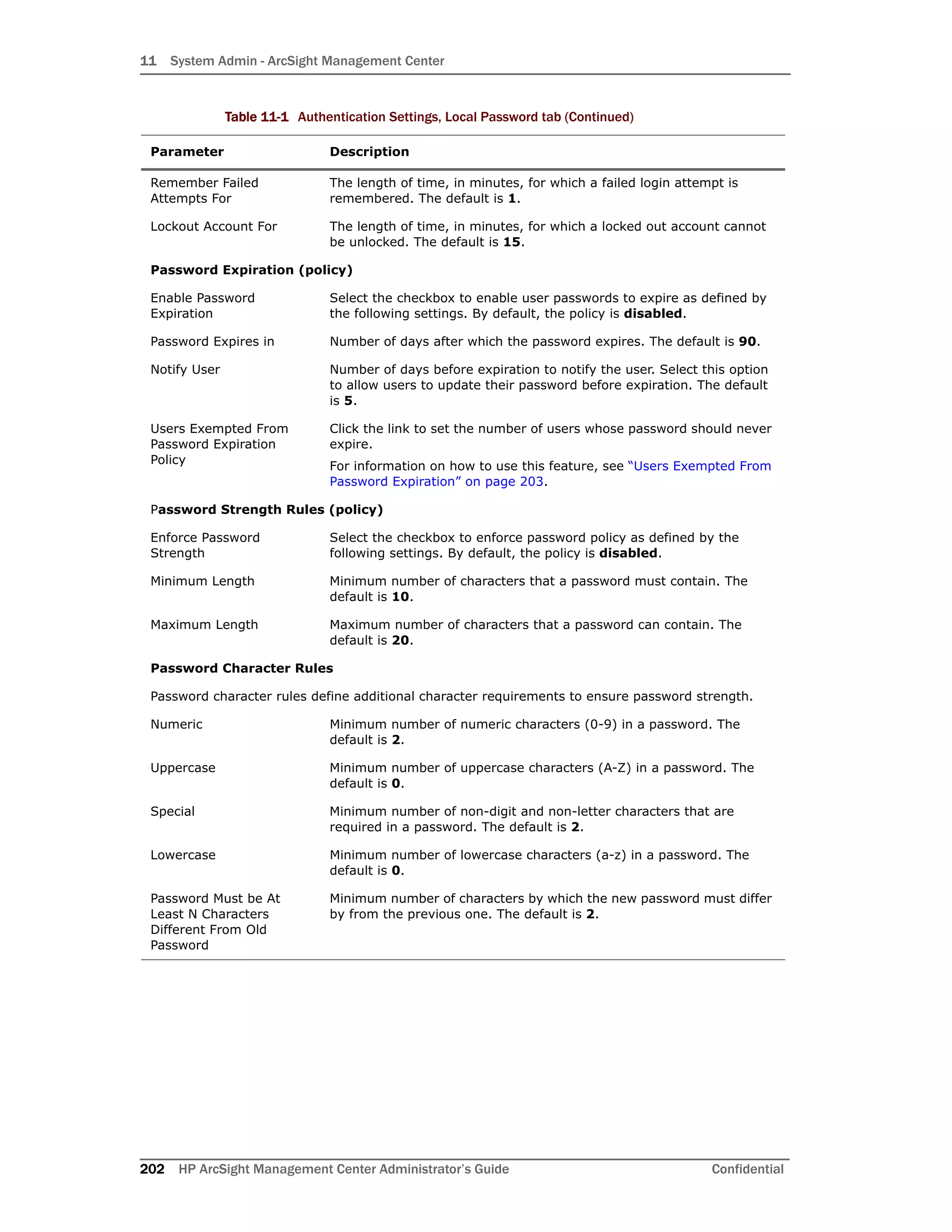
Authentication Local Password
An Authentication Local Password configuration defines a hardware or software system’s
local password options and behavior.
Table 6-15 Authentication Local Password Configuration Parameters
Parameter Data Type Description
Enable Account Lockout* Boolean If Yes, account lockouts are
enabled after an incorrect
password entry.
Lock Out Account after N Failed
Attempts*
Integer Number of failed attempts
before lockout.
Remember Failed Attempts For
(seconds)*
Integer Time, in seconds, between
failed attempts that will trigger
a lockout.
Lockout Account for
(minutes)*
Integer Time, in minutes, that the
account will be locked out.
Enable Password Expiration* Boolean If Yes, password expiration is
enabled
Password Expires in (days)* Integer Interval, in days, after which a
password expires.
Notify User (Days Before
Expiration)*
Integer Days before password
expiration that the user is
notified.
Users Exempted from
Password Expiration Policy
List of comma-separated
strings
Comma-separated list of users
whose passwords will never
expire.
Enforce Password Strength* Boolean If Yes, password strength is
enforced.
Minimum Length (characters)* Integer Minimum number of password
characters.
Maximum Length (characters)* Integer Maximum number of password
characters.
Numeric [0-9]* Integer Minimum number of numeric
password characters.
Upper Case [A-Z]* Integer Minimum number of uppercase
password characters.
Lower Case [a-z]* Integer Minimum number of lowercase
password characters
Special [1$^*...]* Integer Minimum number of special
password characters.
Password Must Be At Least* Integer Minimum number of characters
a new password must differ
from the user’s previous
password.
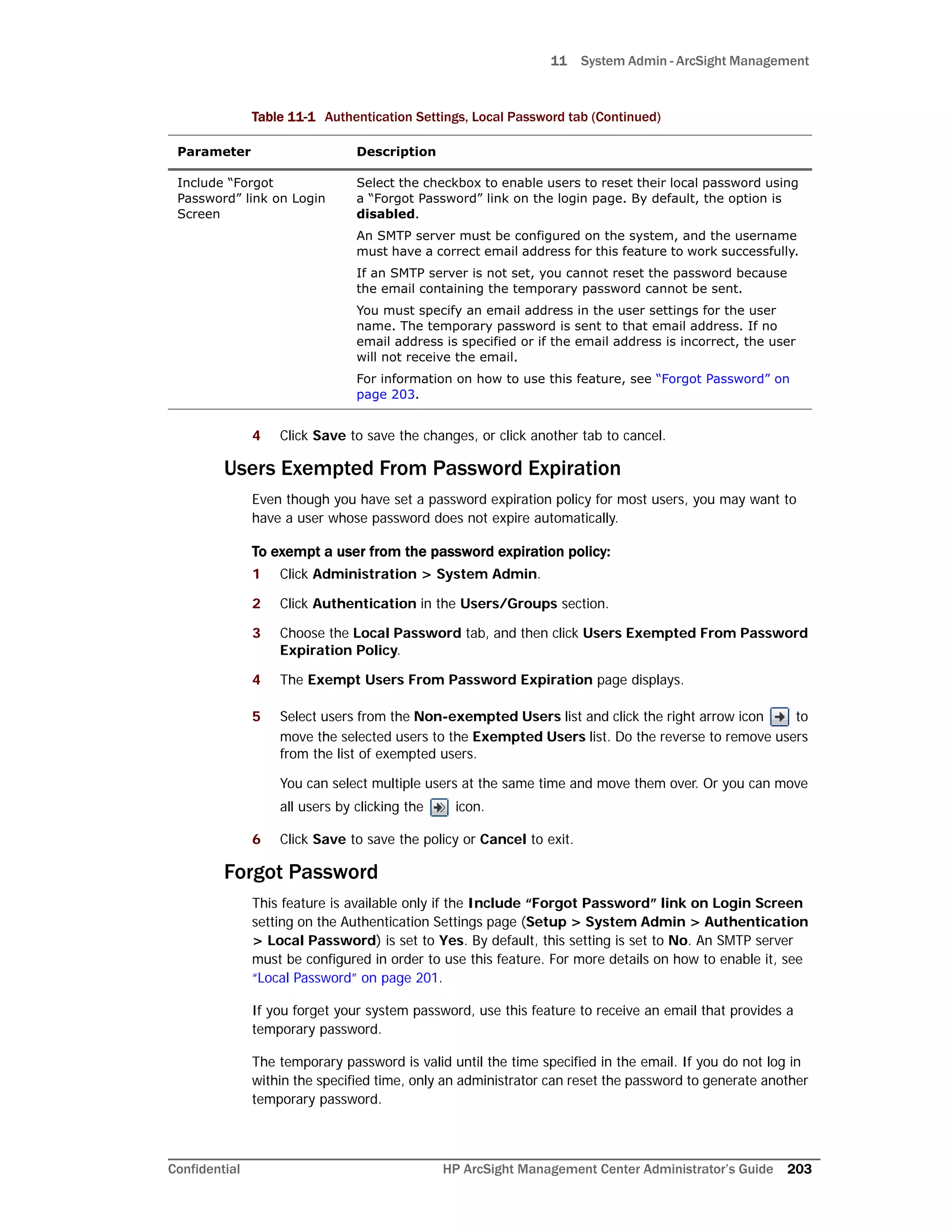
Include “Forgot Password” link
on Login Screen*
Boolean If Yes, a link is provided where
the user can recover a
password.](https://image.slidesharecdn.com/arcmcadminguide1-170531062827/75/ArcSight-Management-Center-2-0-Administrator-s-Guide-129-2048.jpg)
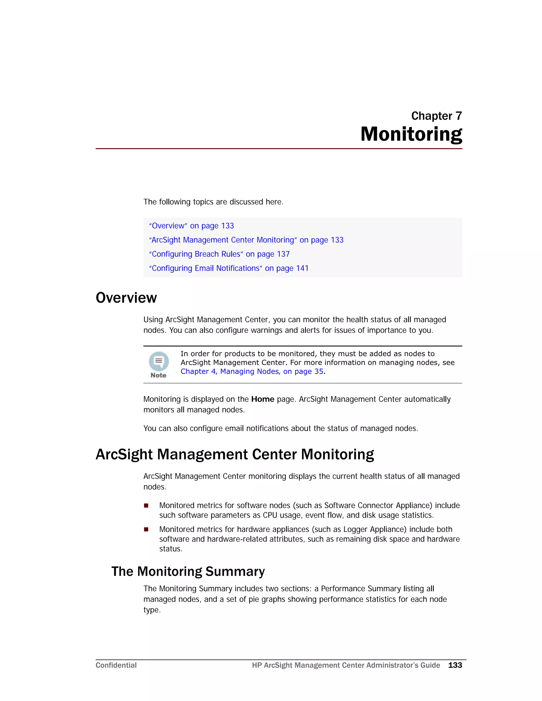
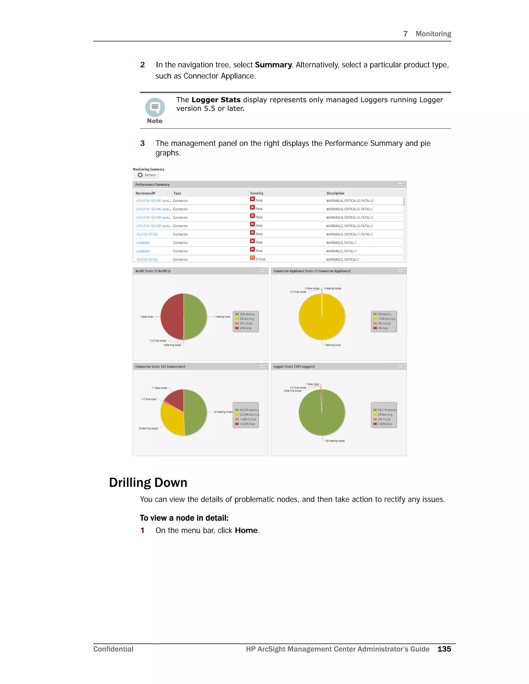
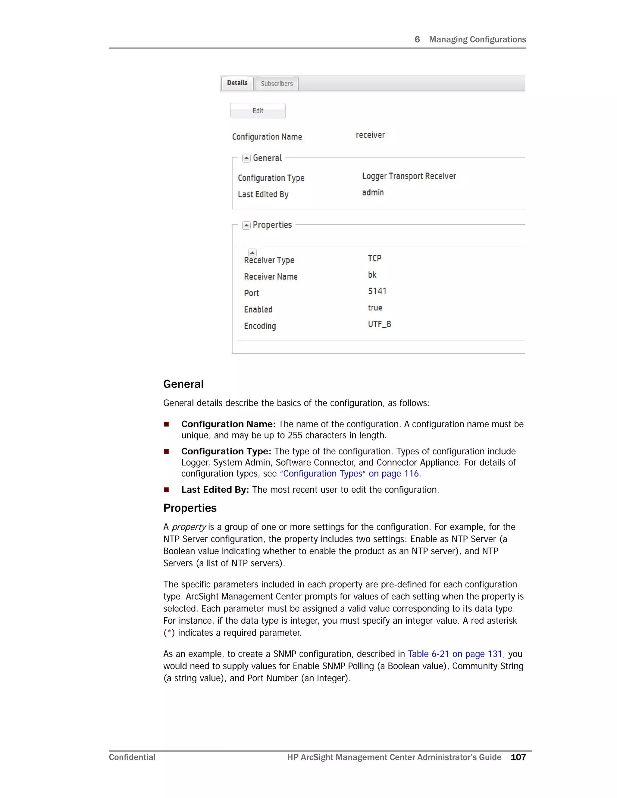
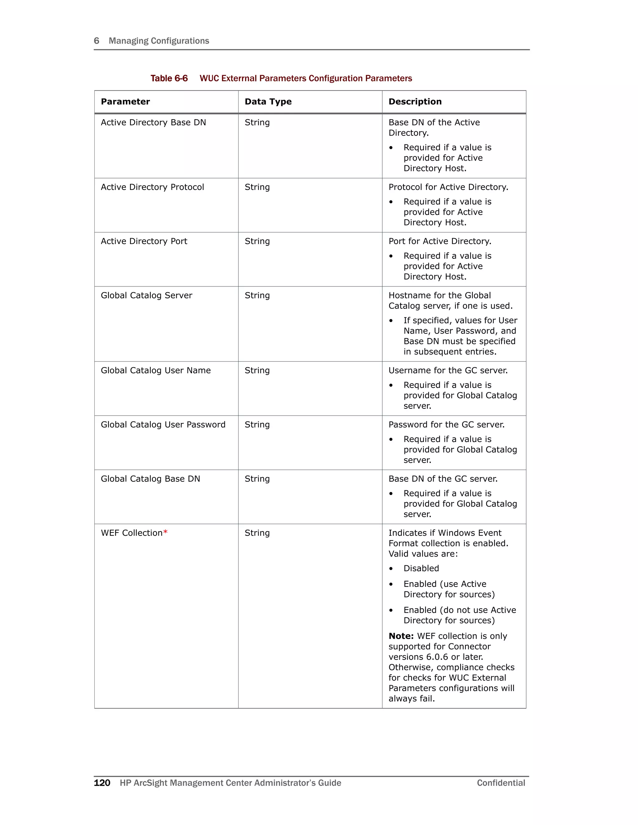
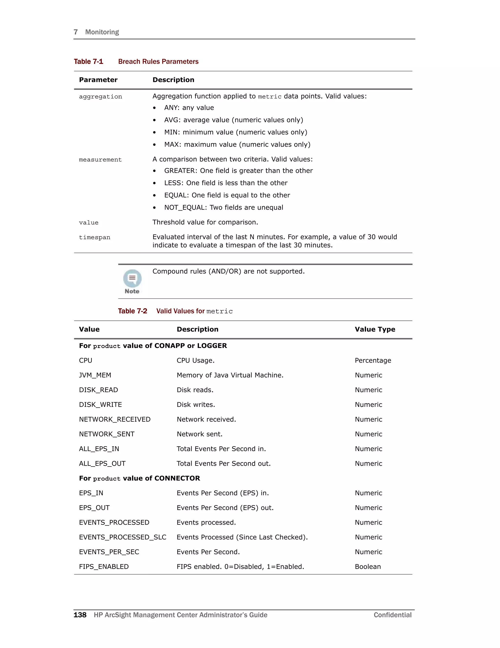
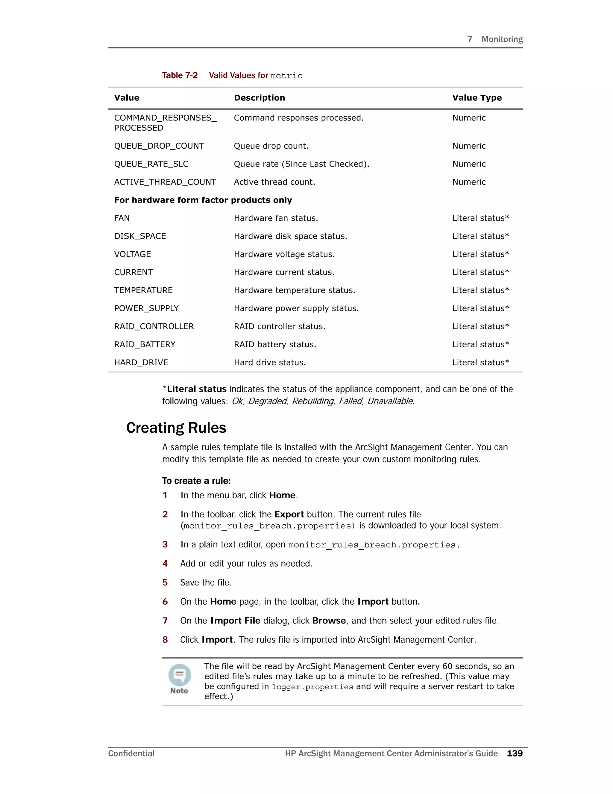
![7 Monitoring
Confidential HP ArcSight Management Center Administrator’s Guide 137
Lead Breach: Short summary of the most severe issue reported by the node.
The node may be experiencing less severe issues as well.
To view all details of a problematic node, select it in the upper table. The lower table
shows all issues associated with the selected node. Each issue is shown with these
identifiers:
Severity: Breach severity.
Metric Type: Metric assigned to the issue.
Time of Occurrence: Local time of the issue’s occurrence, with respect to the
monitoring ArcSight Management Center.
Description: A brief description of the issue.
Configuring Breach Rules
For monitoring purposes, breach rules are defined to generate warnings for each managed
product type. These rules are specified in the file:
<install_dir>/userdata/arcmc/monitor_breach_rules.properties
A rule comprises a set of logical criteria, grouped by a rule identifier. All criteria in the rule
are evaluated together to determine the rule’s total effect.
For example, Rule N checks for the number of input events per second (criterion #1) that
reach a certain type of device (criterion #2). Should this number exceed (criterion #3) a
specified level (criterion #4), then a warning (criterion #5) should be returned.
Each criterion for the breach rule is specified in the format:
breach.rule[<rule identifier>].<parameter>=<value>
where <rule identifier> is the common integer that groups all criteria that apply the
rule.
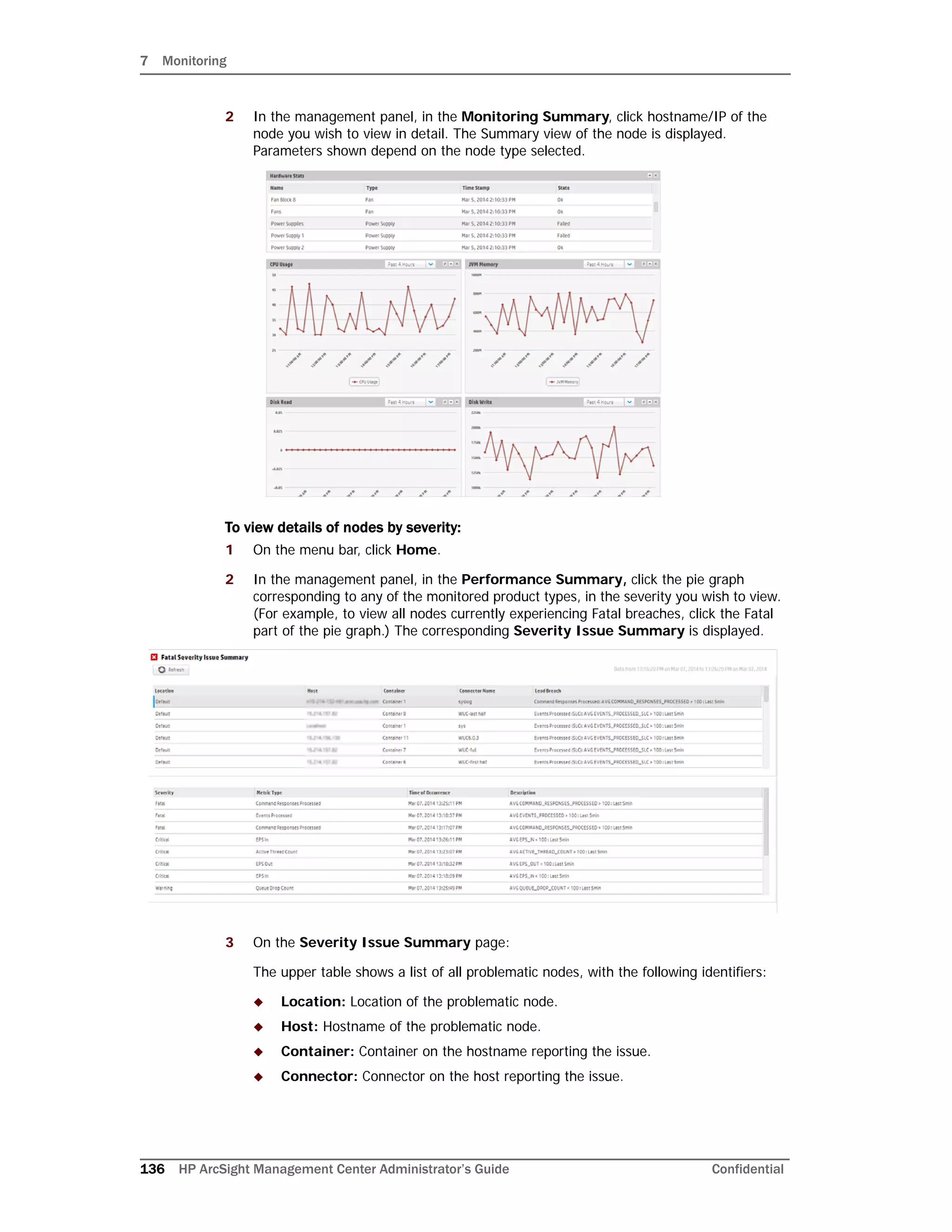
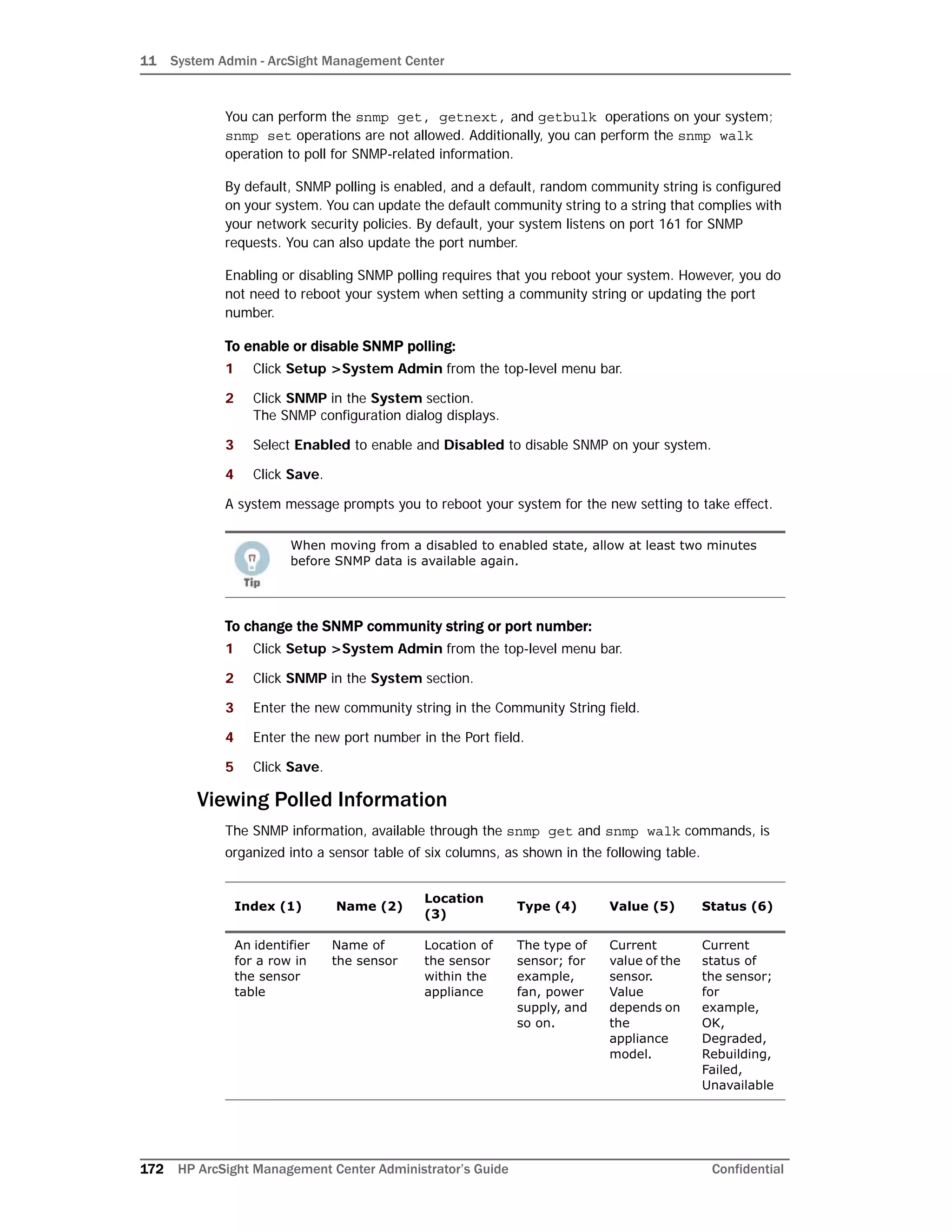
The following table describes breach rules parameters and their valid values.
Table 7-1 Breach Rules Parameters
Parameter Description
product Managed product type. Valid values:
• ARCMC: ArcSight Management Center
• CONAPP: Connector Appliance
• CONNECTOR: SmartConnector
• LOGGER: Logger (versions 5.5 or later only).
uri Applies the rule to only the node specified at the URI (found under node
Path). Use a node’s URI to create a rule that will apply to a single node.
severity Breach severity. Valid values: WARNING, CRITICAL or FATAL.
metric Criterion being measured. For valid values of metric, see Table 7-2.](https://image.slidesharecdn.com/arcmcadminguide1-170531062827/75/ArcSight-Management-Center-2-0-Administrator-s-Guide-137-2048.jpg)
![7 Monitoring
140 HP ArcSight Management Center Administrator’s Guide Confidential
Rule Verification
Note that it is possible to create syntactically valid rules that return confusing or
meaningless alerts. For example, you could create a syntactically valid rule to trigger an
alert if CPU usage goes above 100%, but this usage level does not correspond to any
real-world value and would not return meaningful alerts.
Always verify your rules to ensure that they return meaningful values, to help you best
detect problems and issues.
Rules Examples
Shown here are examples of two custom breach rules.
Rule 1: Warning Breach
Rule 1 specifies the following Warning condition:
“Generate a Warning breach if the average CPU usage of any Connector Appliance in the
past 30 minutes is greater than 70%.”
breach.rule[1].product = CONAPP
breach.rule[1].severity = WARNING
breach.rule[1].metric = CPU
breach.rule[1].aggregation = AVG
breach.rule[1].measurement = GREATER
breach.rule[1].value = 70
breach.rule[1].timespan = 30
Custom Polling Intervals: ArcSight Management Center 2.0 uses three
polling intervals (4 hours, 1 day, and 1 week) associated with metric-data
archive types across ArcSight products. These intervals can be adjusted for
proper usage, if required.
It is strongly recommended that you adjust these intervals only if you fully
understand the impact of the changes.
These intervals can be specified in the file logger.properties using a text
editor.
• 4-hour data: monitoring.data.poll.4hour.cron=10 0/3 * * * ?
This property indicates a poll every 3 minutes, with a minimum allowed
interval of 1 minute.
• 1-day data: monitoring.data.poll.1day.cron=15 0/10 * * * ?
This property indicates a poll every 10 minutes, with a minimum allowed
interval of 5 minutes.
• 1-week data: monitoring.data.poll.1week.cron=20 2 * * * ?
This property indicates a poll every 1 hour, with a minimum allowed
interval of 1 hour.
After making the changes and saving the edited file, a server restart is
required for the changes to take effect.](https://image.slidesharecdn.com/arcmcadminguide1-170531062827/75/ArcSight-Management-Center-2-0-Administrator-s-Guide-140-2048.jpg)
![7 Monitoring
Confidential HP ArcSight Management Center Administrator’s Guide 141
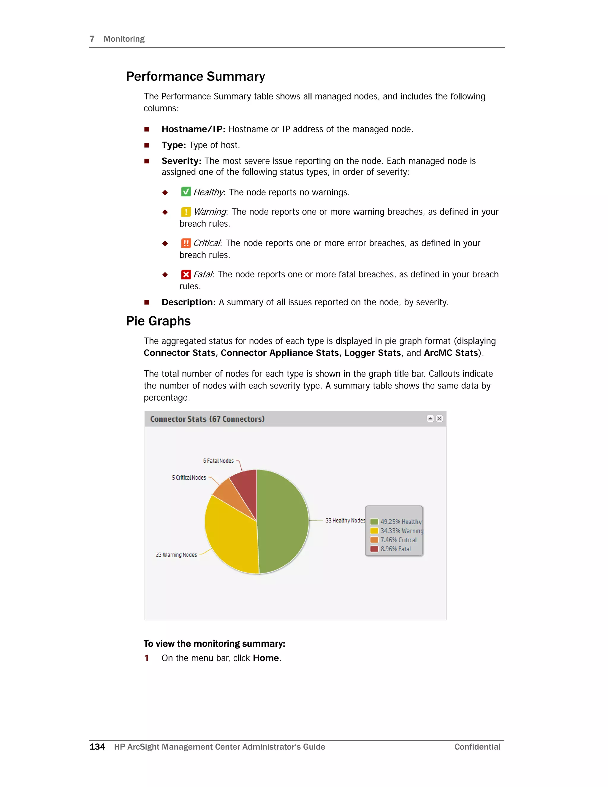
Rule 2: Critical Breach
Rule 2 specifies the following Critical condition:
“Generate a Critical breach if the average CPU usage of any Logger Appliance in the past 5
minutes is greater than 90%.”
breach.rule[2].product = LOGGER
breach.rule[2].severity = CRITICAL
breach.rule[2].metric = CPU
breach.rule[2].aggregation = AVG
breach.rule[2].measurement = GREATER
breach.rule[2].value = 90
breach.rule[2].timespan = 5
Configuring Email Notifications
Email notifications will apprise recipients about monitored nodes being down or out of
communications.
Before configuring email notifications, ensure that values are specified for your SMTP
settings under System Admin > System > SMTP. For more information on SMTP
settings, see “SMTP” on page 168.
To configure email notifications:
1 In a text editor, open the file .../userdata/arcmc/logger.properties.
2 Add a new line with the new property named monitoring.notification.emails
and a value equal to a comma-separated list of email addresses of all administrators
you intend to receive notifications. For example, this value would send email alerts to
address1@example.com and address2@example.com:
monitoring.notification.emails=address1@example.com,
address2@example.com
3 Save the modified logger.properties file.
4 Restart the ArcMC web process.
Example Email Notification
An example of the email sent to recipients is shown here, where <URI> refers to the URI of
the problematic node (found on the Hosts tab in ArcSight Management Center).
Subject: <Email title>
The following nodes are either down or not reachable from ArcSight
Management Center:
Email alerts do not include issues with software connectors. However,
containers may be the subject of email alerts.](https://image.slidesharecdn.com/arcmcadminguide1-170531062827/75/ArcSight-Management-Center-2-0-Administrator-s-Guide-141-2048.jpg)


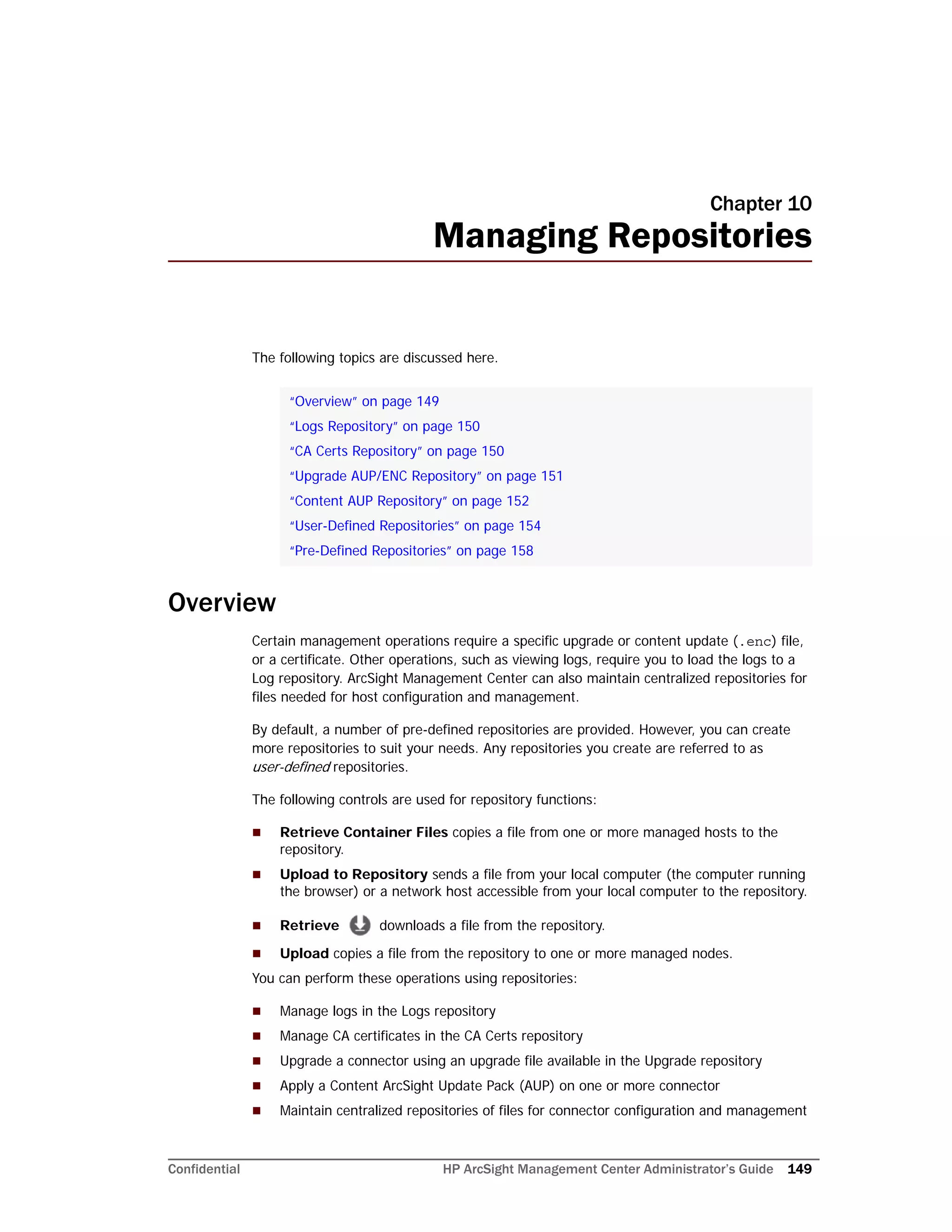
![10 Managing Repositories
Confidential HP ArcSight Management Center Administrator’s Guide 153
Connectors that are unavailable at the time of the AUP file push
Connectors whose current version does not fall in the range of versions that the
Content AUP supports
The ESM destination on a connector
All destinations of a connector that have an ESM destination with the AUP Master flag
set to Yes
Also, when a new connector is added, the highest number Content AUP is pushed
automatically to its destinations.
Applying a New Content AUP
You can add a new content AUP file to the repository and push it automatically to all
applicable managed nodes.
To apply a new Content AUP:
1 Download the new Content AUP version from the support site at
http://softwaresupport.hp.com/ to the computer that you use to connect to ArcMC.
2 From the computer to which you downloaded the AUP file, log in to ArcMC.
3 Click Administration > Repositories.
4 Click Content AUP from the left panel.
5 Click Upload from the management panel.
6 Click Browse and select the file you downloaded earlier.
7 Click Submit to add the specified file to the repository and push it automatically to all
applicable connectors, or Cancel to quit.
You can verify the current Content AUP version on a connector by performing either of
these steps:
Run the GetStatus command on the node destination and check that the value for
aup[acp].version is the same as the AUP version you applied. For information
about running a command on a connector destination, see “Sending a Command to a
Connector” on page 90.
hover over a host name to see the AUP version applied to all destinations of that
connector.
Applying an Older Content AUP
If you need to apply an older Content AUP from the Content AUP repository, delete all
versions newer than the one you want to apply in the repository. The latest version (of the
remaining AUP files) is pushed automatically to all applicable connectors.
To delete a Content AUP from the Content AUP repository:
1 Click Administration > Repositories.
2 Click Content AUP from the left panel.
3 Locate the AUP file that you want to delete and click the associated icon. Repeat
for multiple files.](https://image.slidesharecdn.com/arcmcadminguide1-170531062827/75/ArcSight-Management-Center-2-0-Administrator-s-Guide-153-2048.jpg)
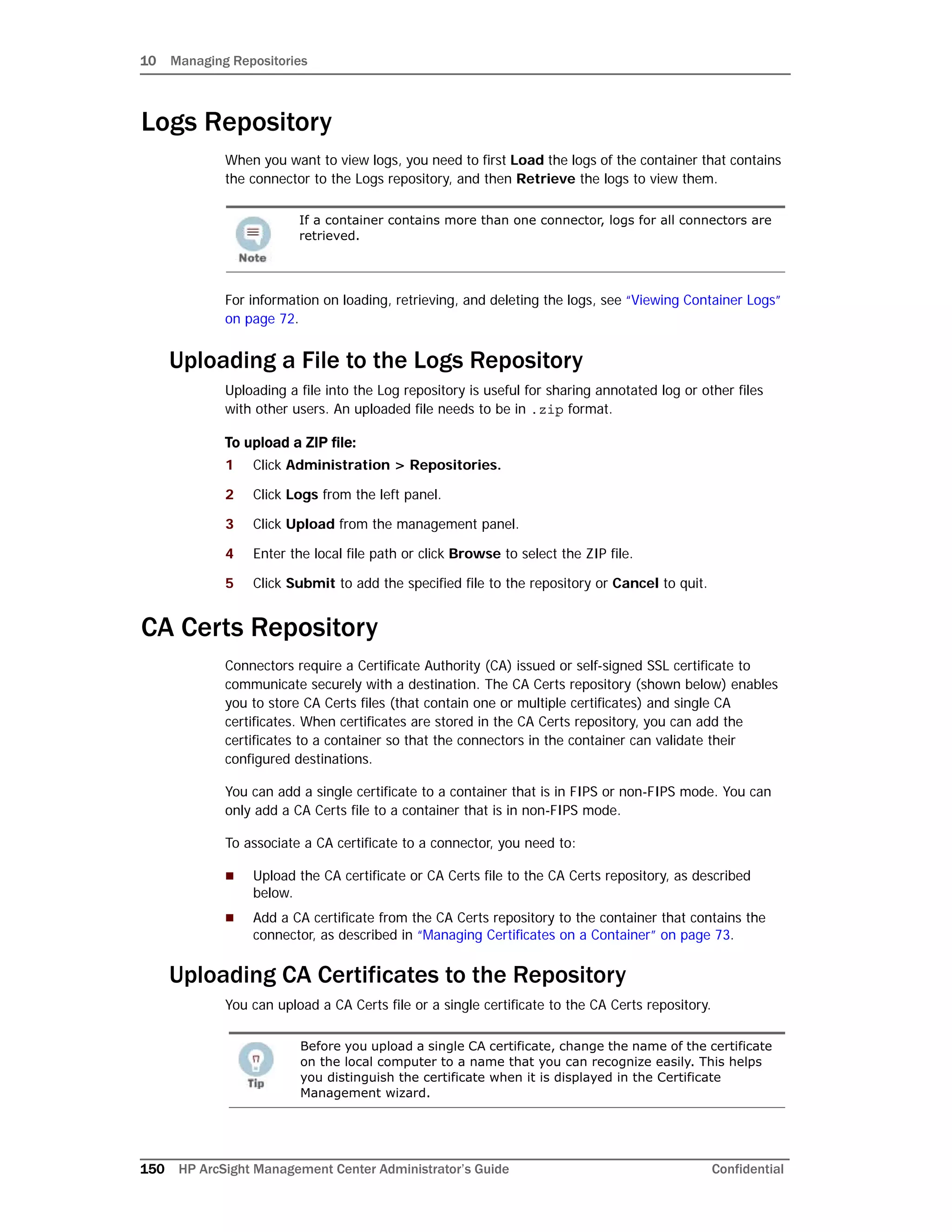
![10 Managing Repositories
Confidential HP ArcSight Management Center Administrator’s Guide 155
4 Click Save at the bottom of the page.
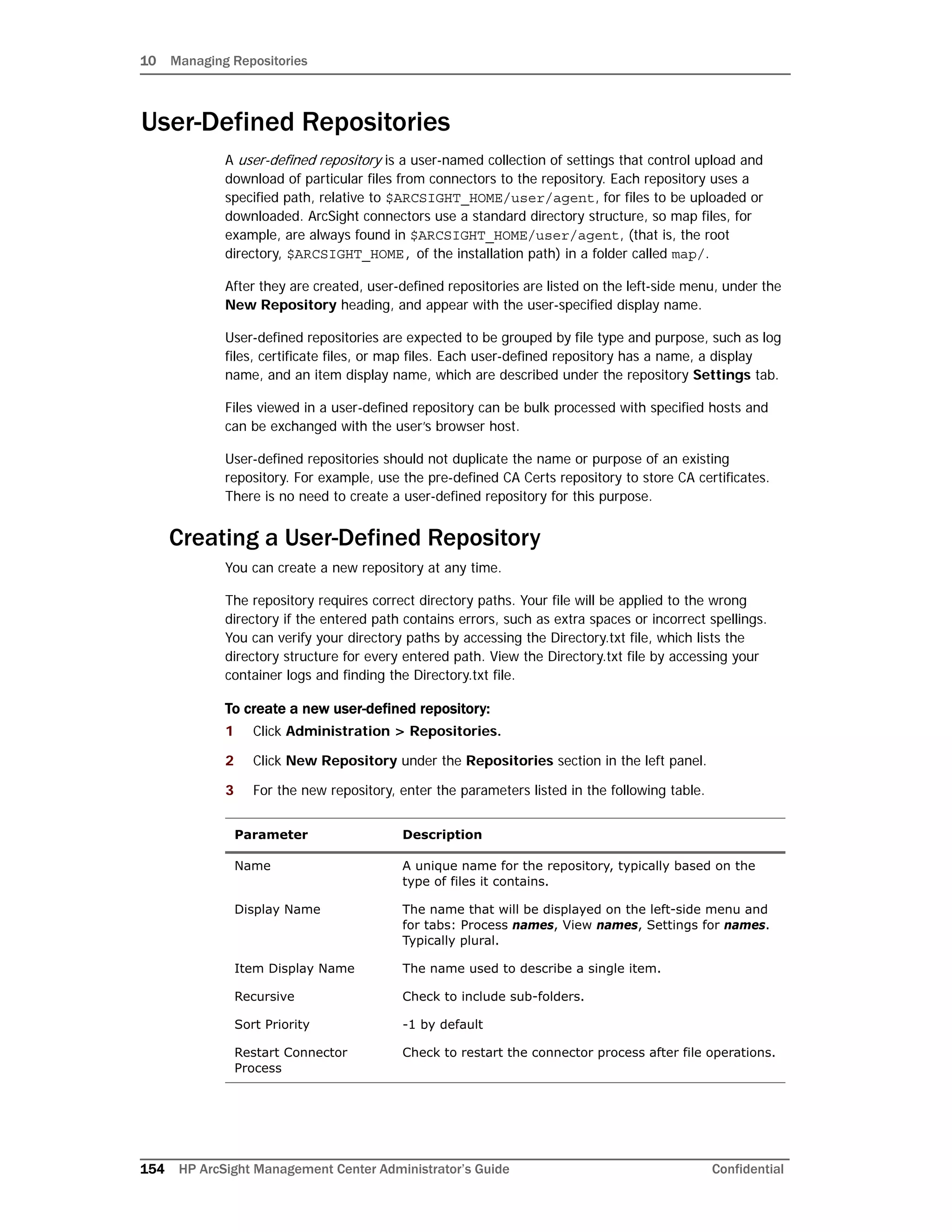
The new repository displays under the New Repository heading in the left-side
window panel.
Retrieving Container Files
The Retrieve Container Files button copies a file from one or more containers to a
repository. The specific files that are retrieved depend on the settings of the repository.
To retrieve a container file:
1 Click Administration > Repositories.
2 In the left panel, under Repositories, click the name of the repository to which you
want to copy connector files.
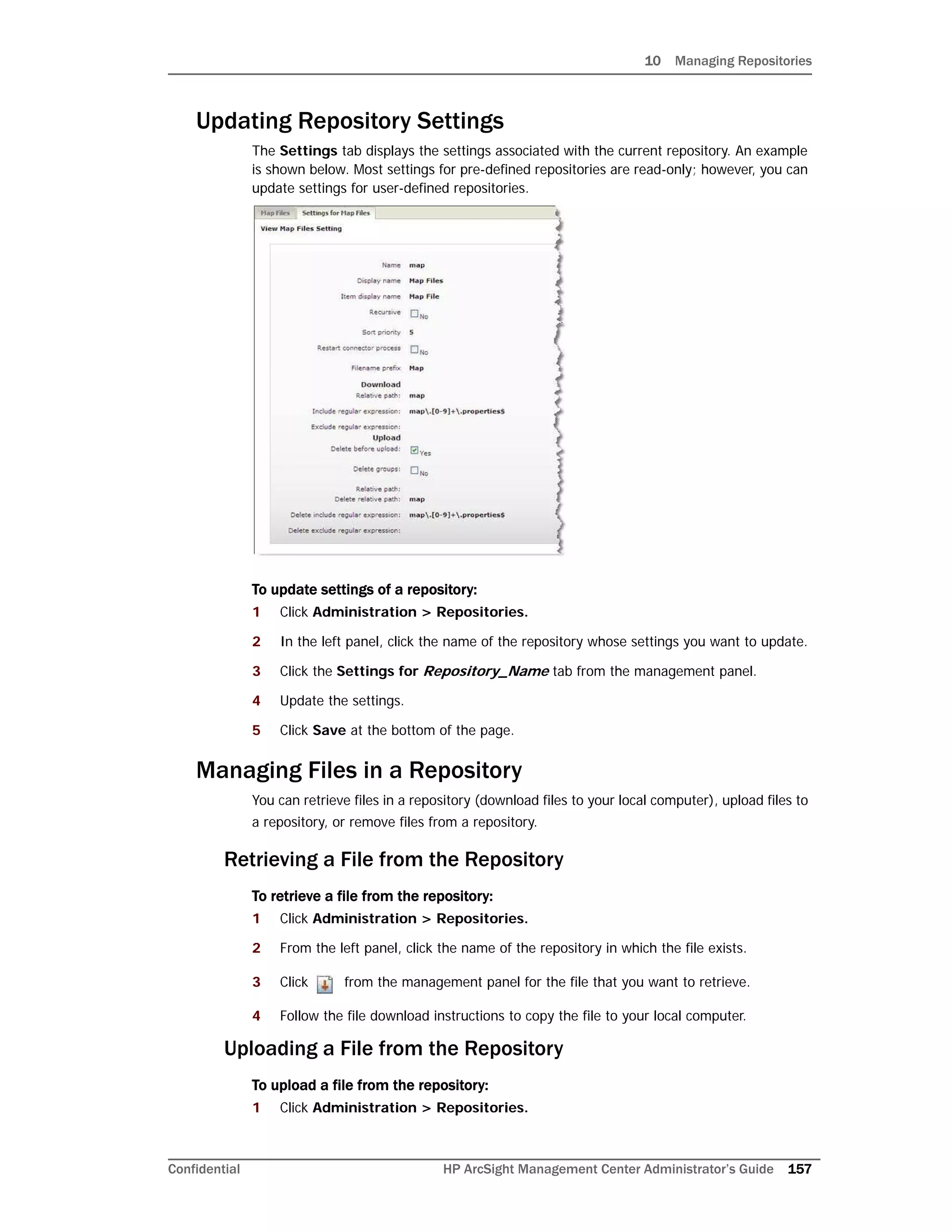
Filename Prefix An identifying word that is included in the names of
retrieved files. For example, map files are identified by Map
in the file name:
localhost_Container_-1.Map-2009-04-06_12-22-25-607
.zip
Relative path
(Download)
The path for download, relative to $ARCSIGHT_HOME, for
example, user/agent/map or user/agent/flexagent.
Leave this field blank to specify files in $ARCSIGHT_HOME.
Note: The relative path is used for download only.
Include Regular
Expression
A description of filenames to include. Use .* to specify all
files. The following example selects properties files that
consist of map. followed by one or more digits, followed by
.properties:
map.[0-9]+.properties$
Exclude Regular
Expression
A description of filenames to exclude. The following
example excludes all files with a certain prefix or in the
agentdata folder.
(agentdata/|cwsapi_fileset_).*$
Delete Before Upload Check to delete earlier copies before upload.
CAUTION: If you check Delete Before Upload and do not
specify a Relative path (Upload), all files and folders in
current/user/agent will be deleted.
Delete Groups Whether to delete folders recursively in
$ARCSIGHT_HOME/user/agent/map directory.
Relative path (Upload) The path for upload, relative to
$ARCSIGHT_HOME/current/user/agent/flexagent/
<connectorname>
Delete Relative Path Whether the directory specified in Relative Path (Upload)
and its contents should be removed when a file is uploaded
from the repository.
Delete Include Regular
Expression
Typically the same as the Include Regular Expression.
Delete Exclude Regular
Expression
Typically the same as the Exclude Regular Expression.
Parameter Description](https://image.slidesharecdn.com/arcmcadminguide1-170531062827/75/ArcSight-Management-Center-2-0-Administrator-s-Guide-155-2048.jpg)
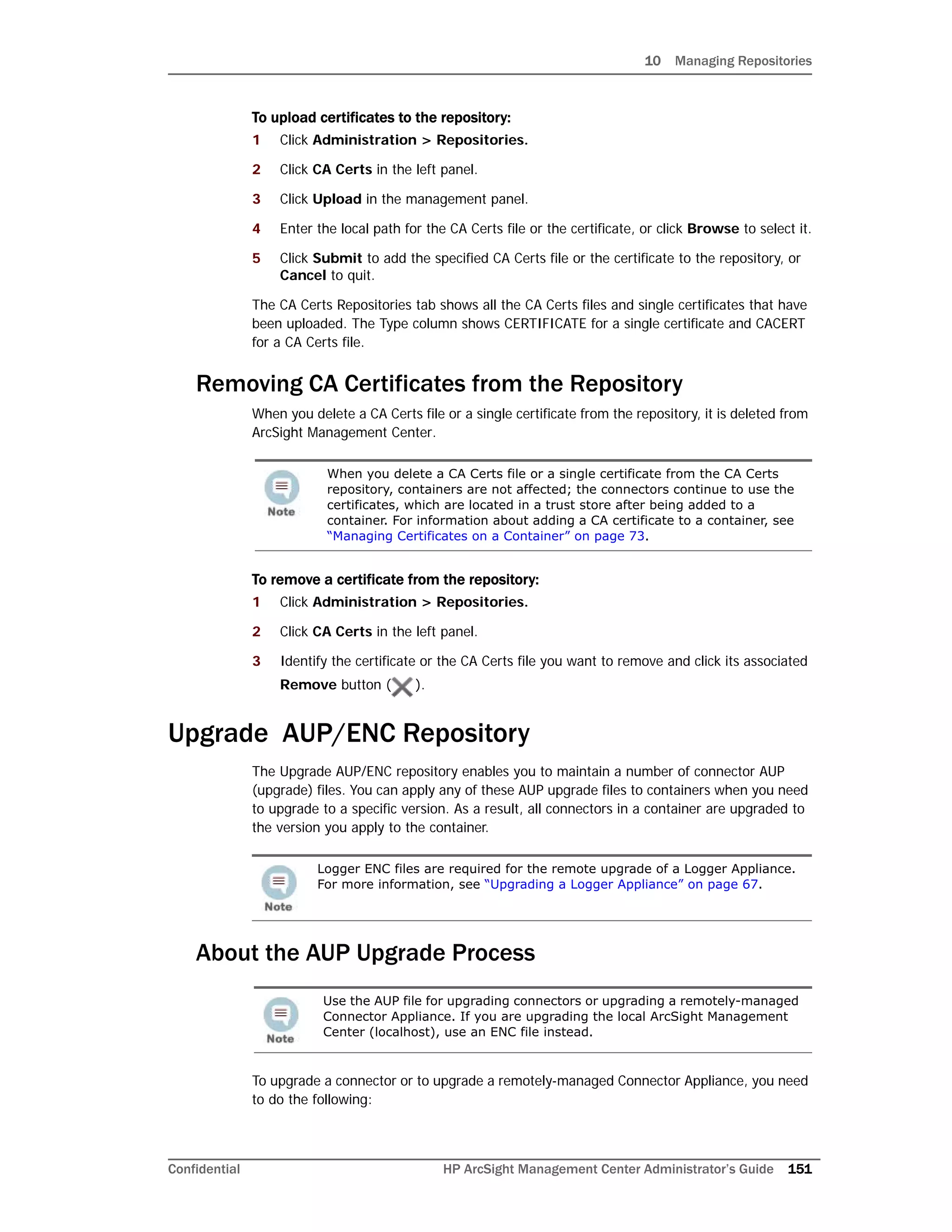
![10 Managing Repositories
Confidential HP ArcSight Management Center Administrator’s Guide 159
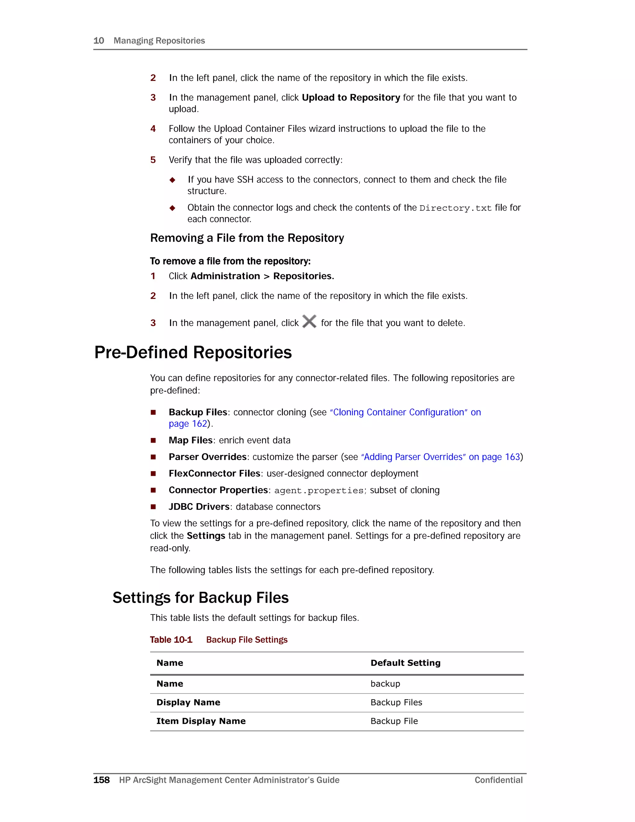
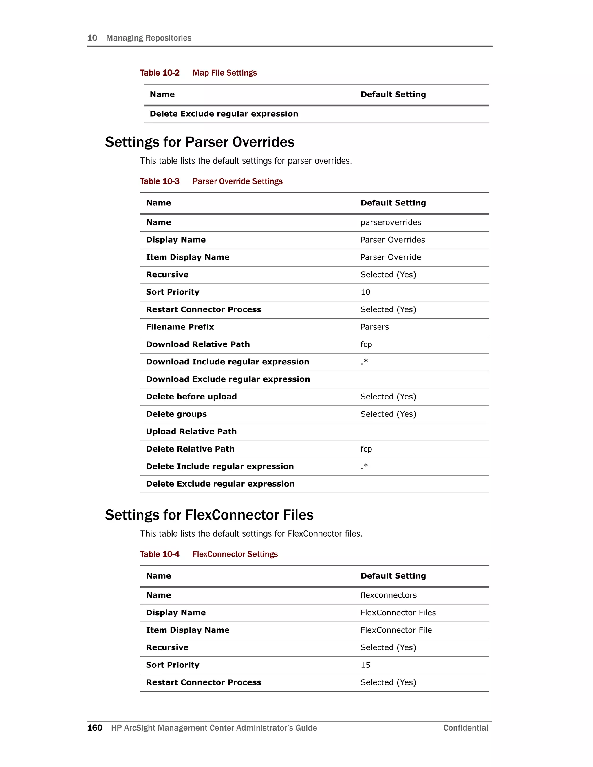
Settings for Map Files
This table lists the default settings for map files.
Recursive Selected (Yes)
Sort Priority 0
Restart Connector Process Selected (Yes)
Filename Prefix ConnectorBackup
Download Relative Path
Download Include regular expression
Download Exclude regular expression (agentdata/|cwsapi_fileset_).*$
Delete before upload Selected (Yes)
Delete groups Selected (Yes)
Upload Relative Path
Delete Relative Path
Delete Include regular expression
Delete Exclude regular expression (agentdata/|cwsapi_fileset_).*$
Table 10-2 Map File Settings
Name Default Setting
Name map
Display Name Map Files
Item Display Name Map File
Recursive Deselected (No)
Sort Priority 5
Restart Connector Process Deselected (No)
Filename Prefix Map
Download Relative Path map
Download Include regular expression map.[0-9]+.properties$
Download Exclude regular expression
Delete before upload Selected (Yes)
Delete groups Deselected (No)
Upload Relative Path
Delete Relative Path map
Delete Include regular expression map.[0-9]+.properties$
Table 10-1 Backup File Settings
Name Default Setting](https://image.slidesharecdn.com/arcmcadminguide1-170531062827/75/ArcSight-Management-Center-2-0-Administrator-s-Guide-159-2048.jpg)
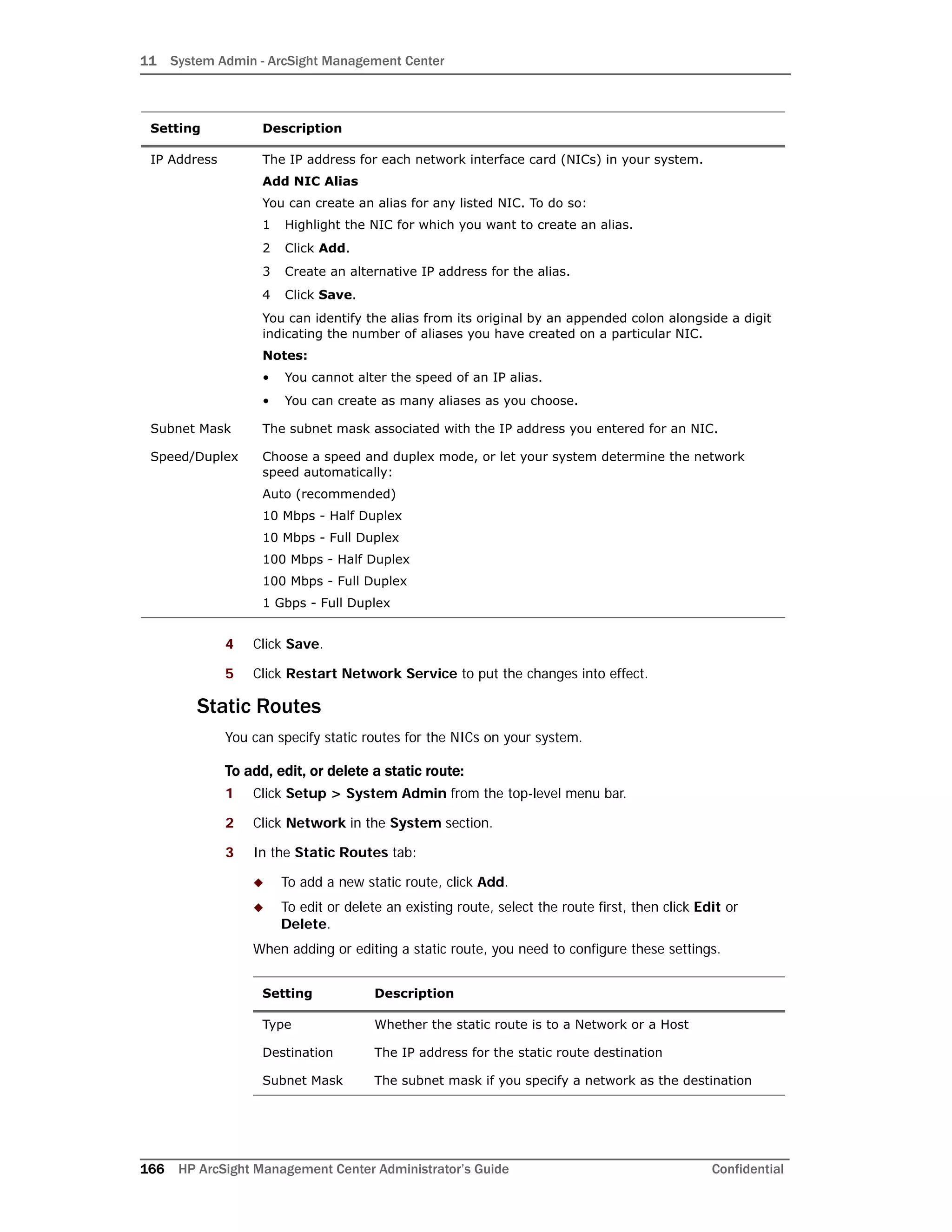
![11 System Admin - ArcSight Management
Confidential HP ArcSight Management Center Administrator’s Guide 179
This tool is equivalent to the Linux command netstat -pn [-t] [-u] [-w] [a]
[-l] [-c].
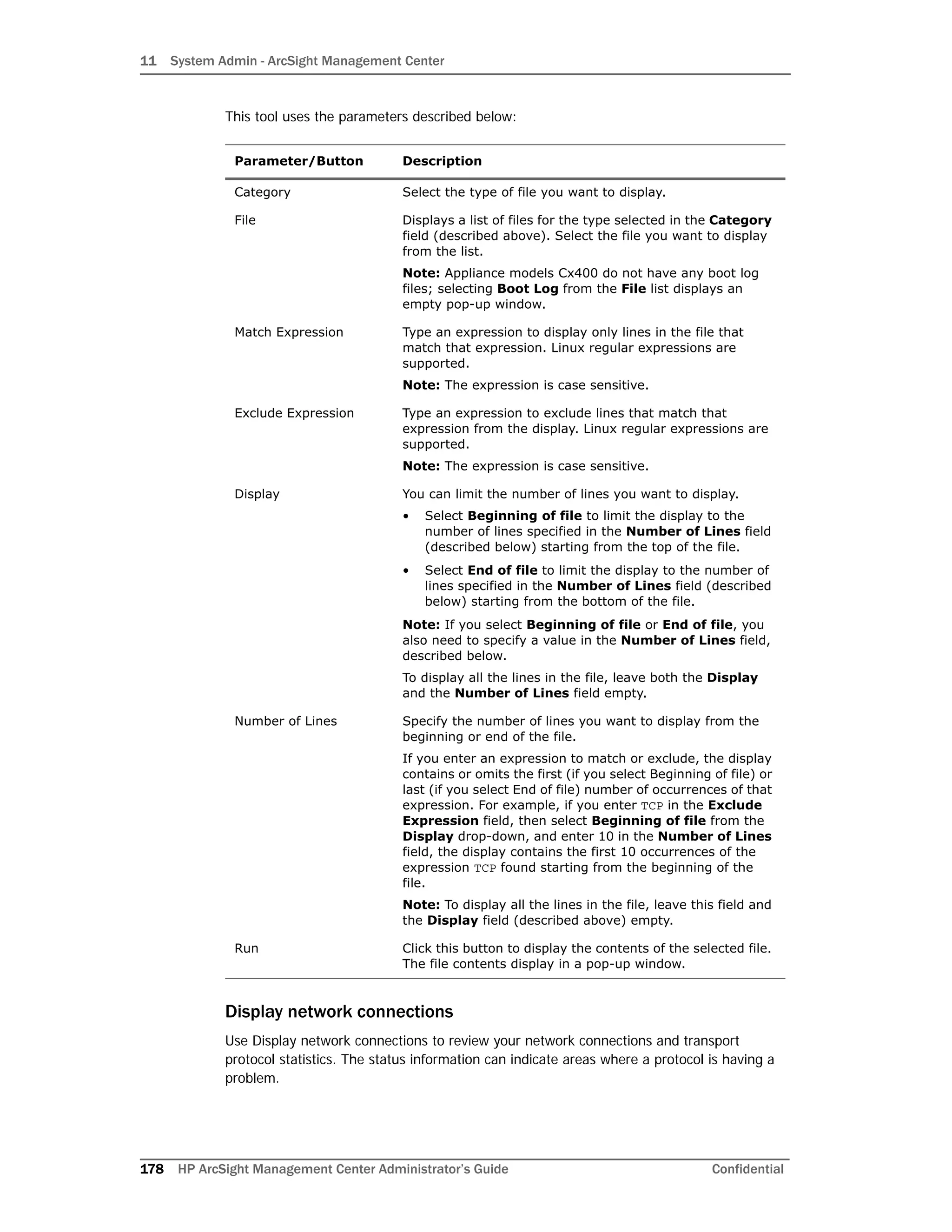
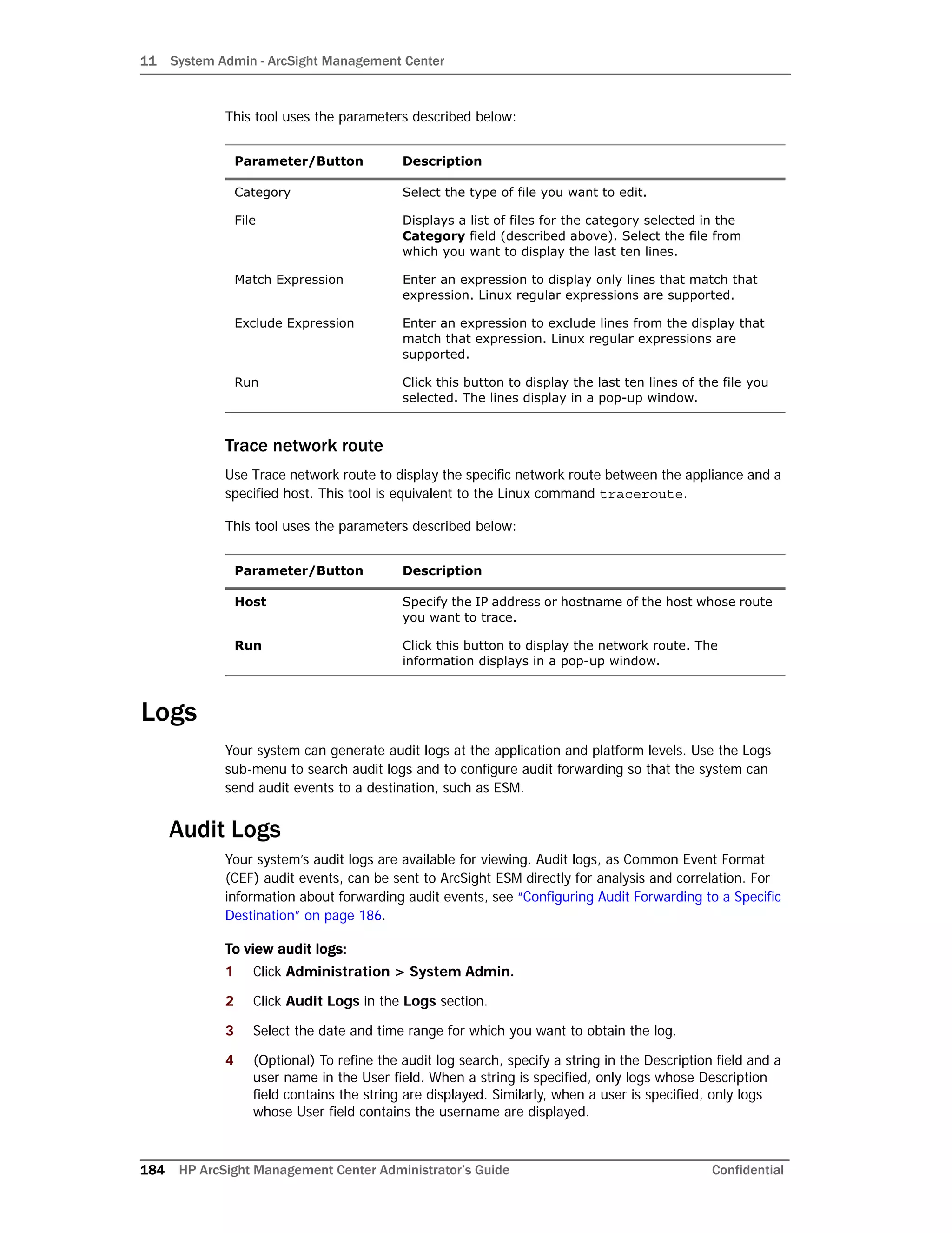
This tool uses the parameters described below:
Display network interface details
Use Display network interface details to display the status of a currently active interface on
the appliance. This tool is equivalent to the Linux command ifconfig.
This tool uses the parameters described below:
Parameter/Button Description
Protocol Leave this field empty to display statistics for all transport
protocols or select from these options:
• RAW only displays raw IP protocol statistics. This
option is equivalent to the netstat Linux command
option -w.
• TCP only displays TCP protocol statistics. This option is
equivalent to the netstat Linux command option -t.
• UDP only displays UDP protocol statistics. This option
is equivalent to the netstat Linux command option -u.
Connection Leave this field empty to display information for all
non-listening connections or select from these options:
• All connections displays information for all current
connections. This option is equivalent to the netstat
Linux command option -a.
• Listening connections displays information for
listening connections only. This option is equivalent to
the netstat Linux command option -l.
Mode Select Run Continuously to poll the network status
continuously every five minutes. This option is equivalent
to the netstat Linux command option -c.
When Run Continuously is not selected, the network
status is polled once.
Match Expression Enter an expression to display only lines that match that
expression in the output. Linux regular expressions are
supported.
Exclude Expression Enter an expression to exclude lines that match that
expression from the output. Linux regular expressions are
supported.
Run Click this button to display the network connection
information. The information displays in a pop-up window.
Parameter/Button Description
Interface Select the network interface on the appliance whose status
you want to display.
Note: If you leave this field empty, the status of all active
network interfaces display.
Run Click this button to display the status of the selected
network interface. The status displays in a pop-up window.](https://image.slidesharecdn.com/arcmcadminguide1-170531062827/75/ArcSight-Management-Center-2-0-Administrator-s-Guide-181-2048.jpg)
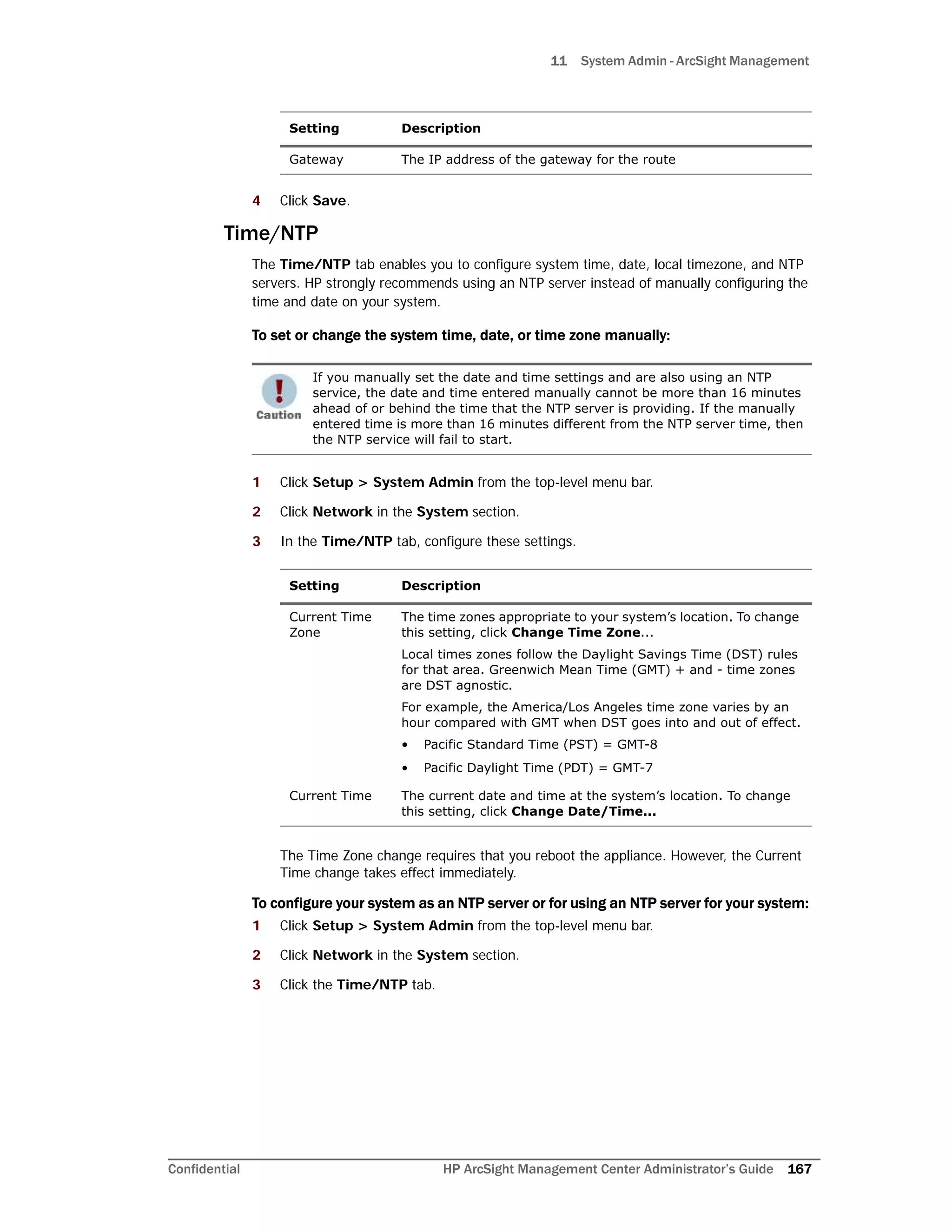
![11 System Admin - ArcSight Management
Confidential HP ArcSight Management Center Administrator’s Guide 183
Scan network ports
Use Scan network ports to scan a specific host on the network for open ports. This tool is
equivalent to the Linux command nmap [-p].
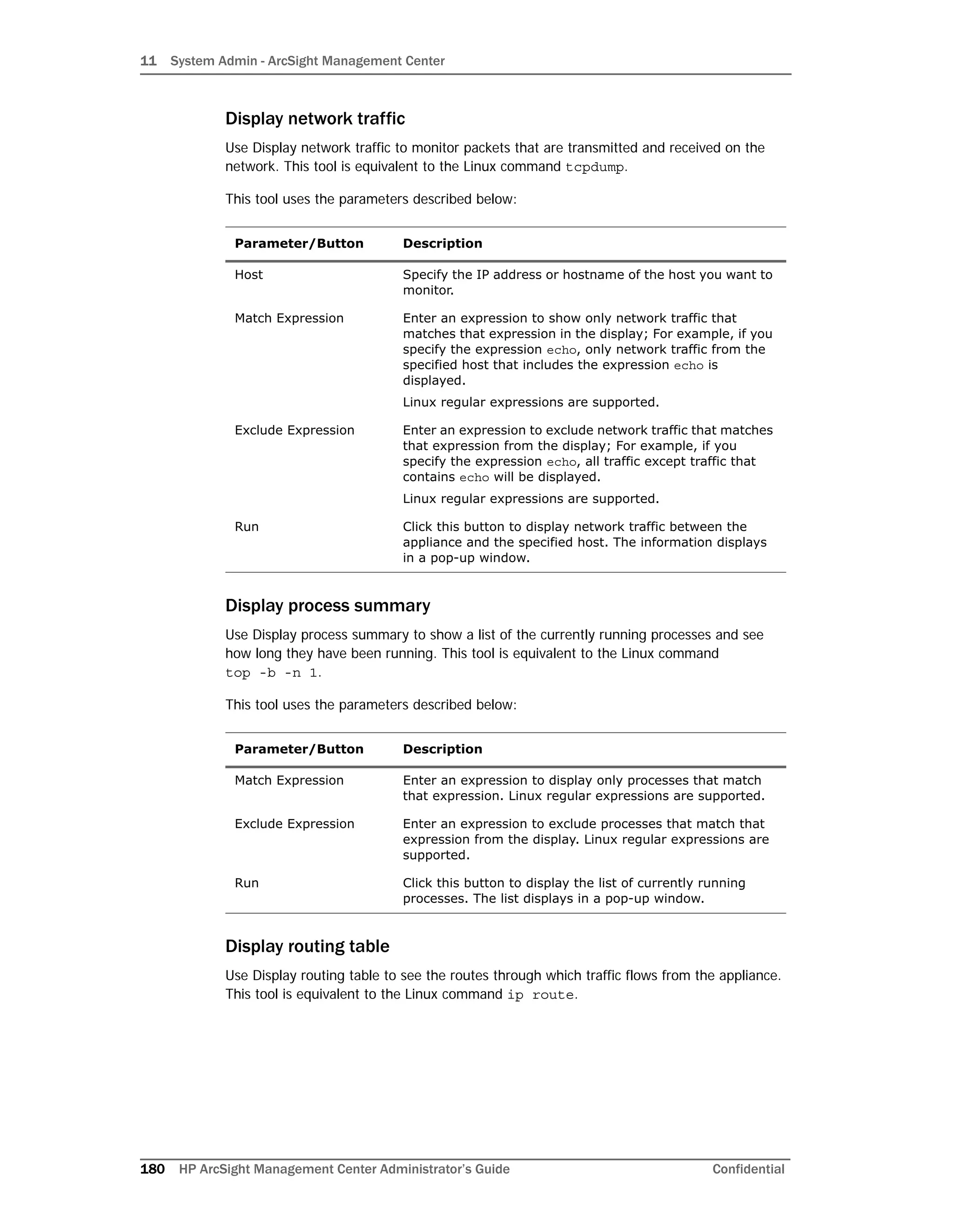
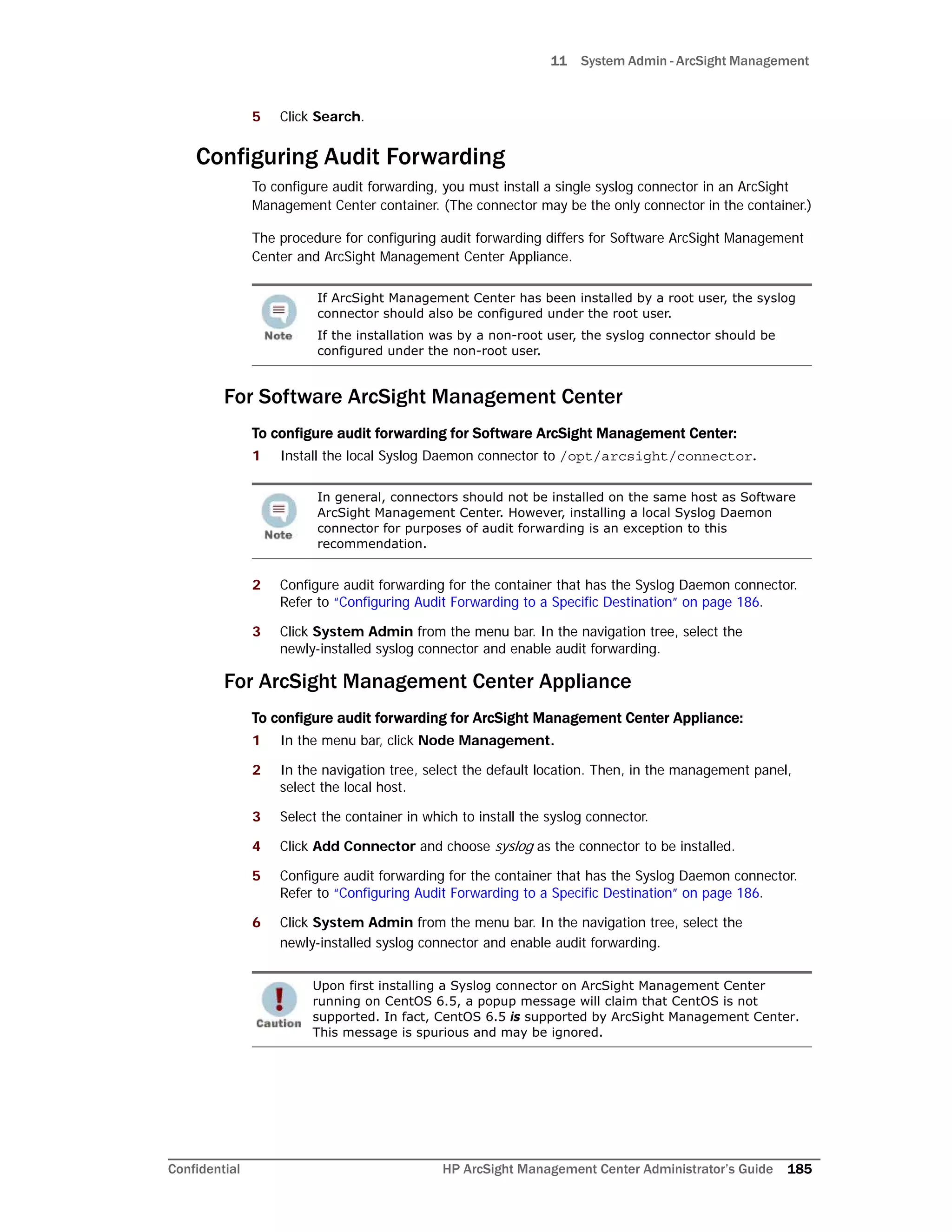
This tool uses the parameters described below:
Send signal to container
Use Send signal to container to send a terminate command to a container. This tool is
equivalent to the Linux command kill -severity (where severity is either -15 or
-9).
This tool uses the parameters described below:
Tail file
Use Tail file to display the last ten lines of a system, application, or log file. This tool is
equivalent to the Linux command tail -f.
Run Click this button to look up the hostname in the Domain
Name Server. The result displays in a pop-up window.
Parameter/Button Description
Host Specify the IP address or hostname of the host whose ports
you want to scan.
Port Range Optional. Specify a range of ports you want to scan.
Separate port numbers in a range by a dash (-) and
individual port numbers by a comma. For example, 80-90,
8080.
If you do not provide a port range, all ports on the specified
host are scanned.
This option is equivalent to the netstat Linux command
option -p.
Run Click this button to start scanning ports on the specified
host. The result displays in a pop-up window.
Parameter/Button Description
Severity Select the severity of the terminate command you want to
send to the container. You can select KILL (Linux kill
command option -9) or TERM (Linux kill command option
-15).
Container Select the container to which you want to send the signal.
Run Click this button to send the signal. The result displays in a
pop-up window.
Parameter/Button Description](https://image.slidesharecdn.com/arcmcadminguide1-170531062827/75/ArcSight-Management-Center-2-0-Administrator-s-Guide-185-2048.jpg)
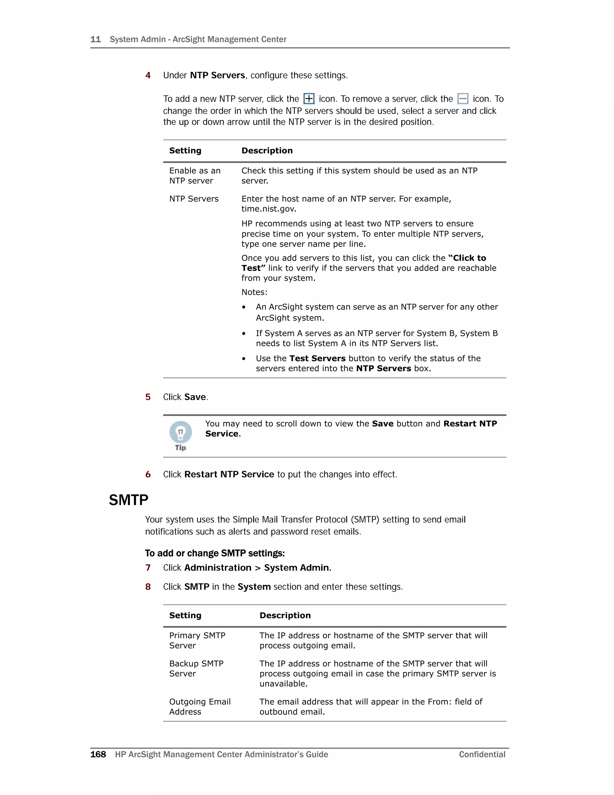
![11 System Admin - ArcSight Management Center
192 HP ArcSight Management Center Administrator’s Guide Confidential
6 Enter a password.
7 Click Save.
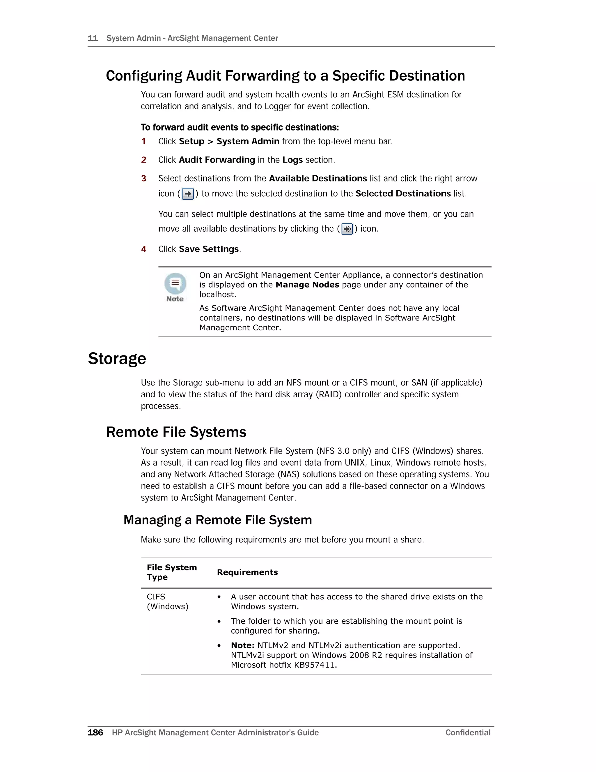
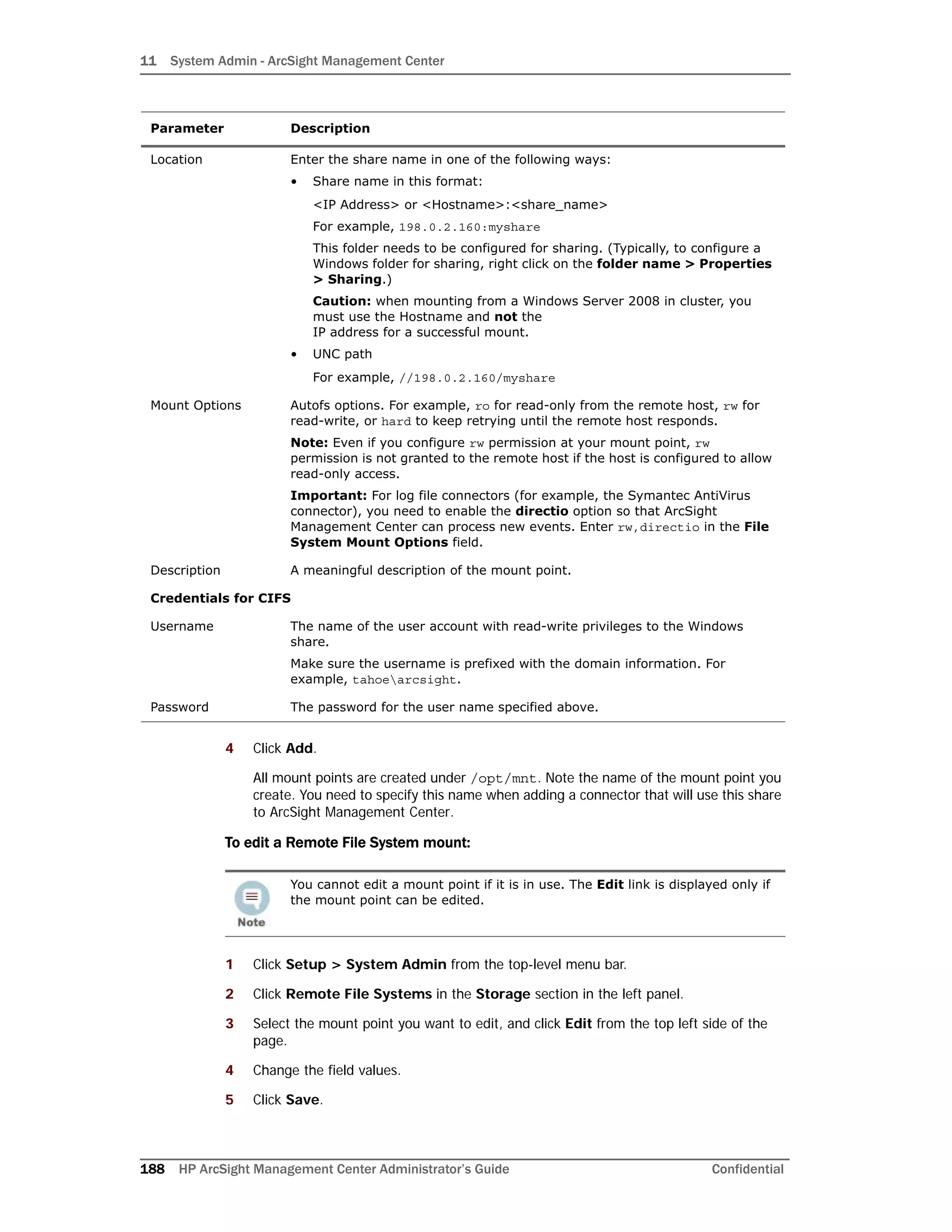
Adding a Subdirectory
Based on naming convention, incoming log files from different devices can potentially
conflict within the same directory. To prevent this, you can create subdirectories to
separate them. This window also shows the current size of the subdirectory.
To add files to the subdirectory:
1 From within the appliance, go to Setup > System Admin > FTP.
2 In the Subdirectory window, click Add to name the subdirectory.
The name appears in the window and displays its current size. Ensure that the
directory name matches the one configured on the FTP server.
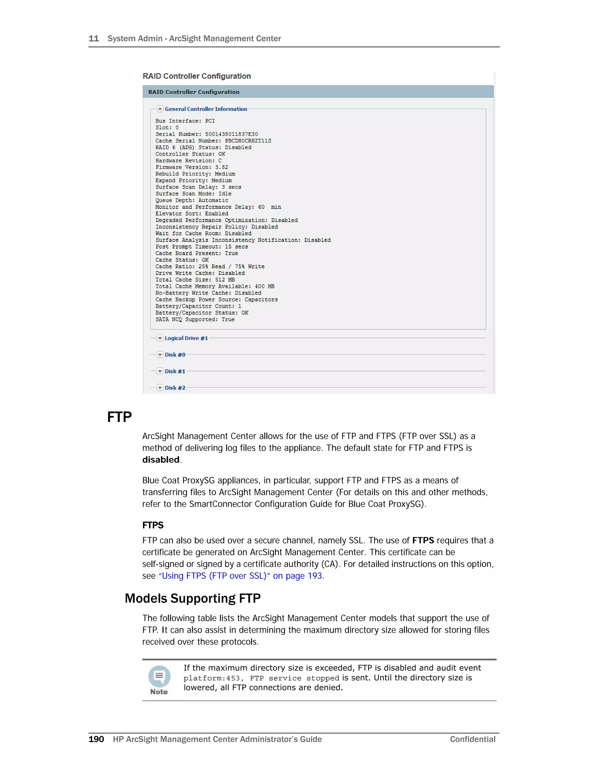
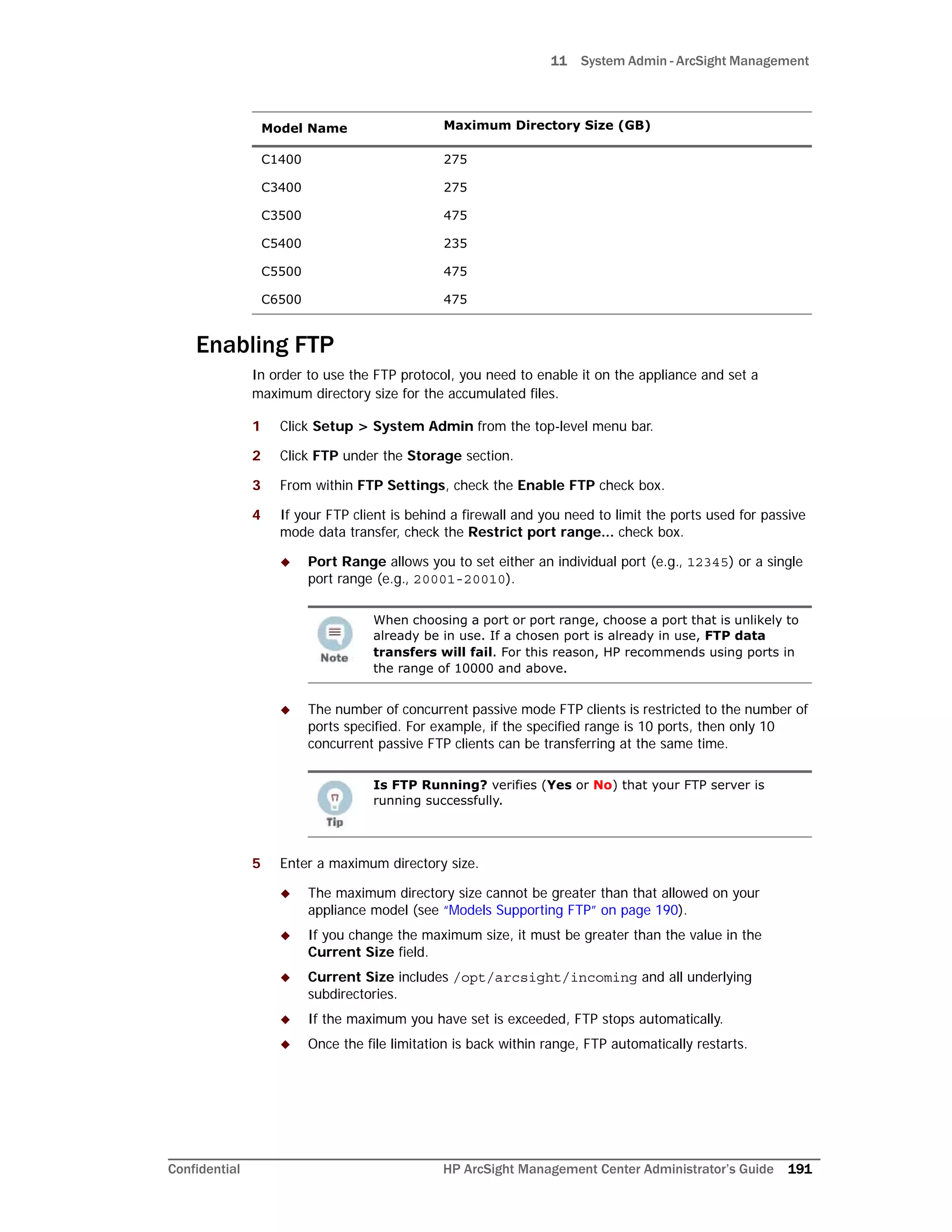
Processing Log Data Received via FTP
Receiving input from a connector via FTP requires that some steps be performed outside of
the appliance. The following steps allow for the successful transfer of log data.
1 Enable FTP on the appliance. For detailed instructions, see “Enabling FTP” on
page 191.
2 Configure the SmartConnector. For instructions on how to do this, see the
SmartConnector Configuration Guide for Blue Coat ProxySG.
Anonymous FTP is not supported.
• Only file put operations are supported by the FTP server. There is no
capability to retrieve data from the appliance.
• Data is processed faster and more efficiently when transferred in
many small files in lieu of fewer large files.
Creating subdirectories is a good practice, as it allows you to verify how much
space is being used and to easily delete subsets of file data.
When naming subdirectories, the standard Linux directory naming
conventions apply.
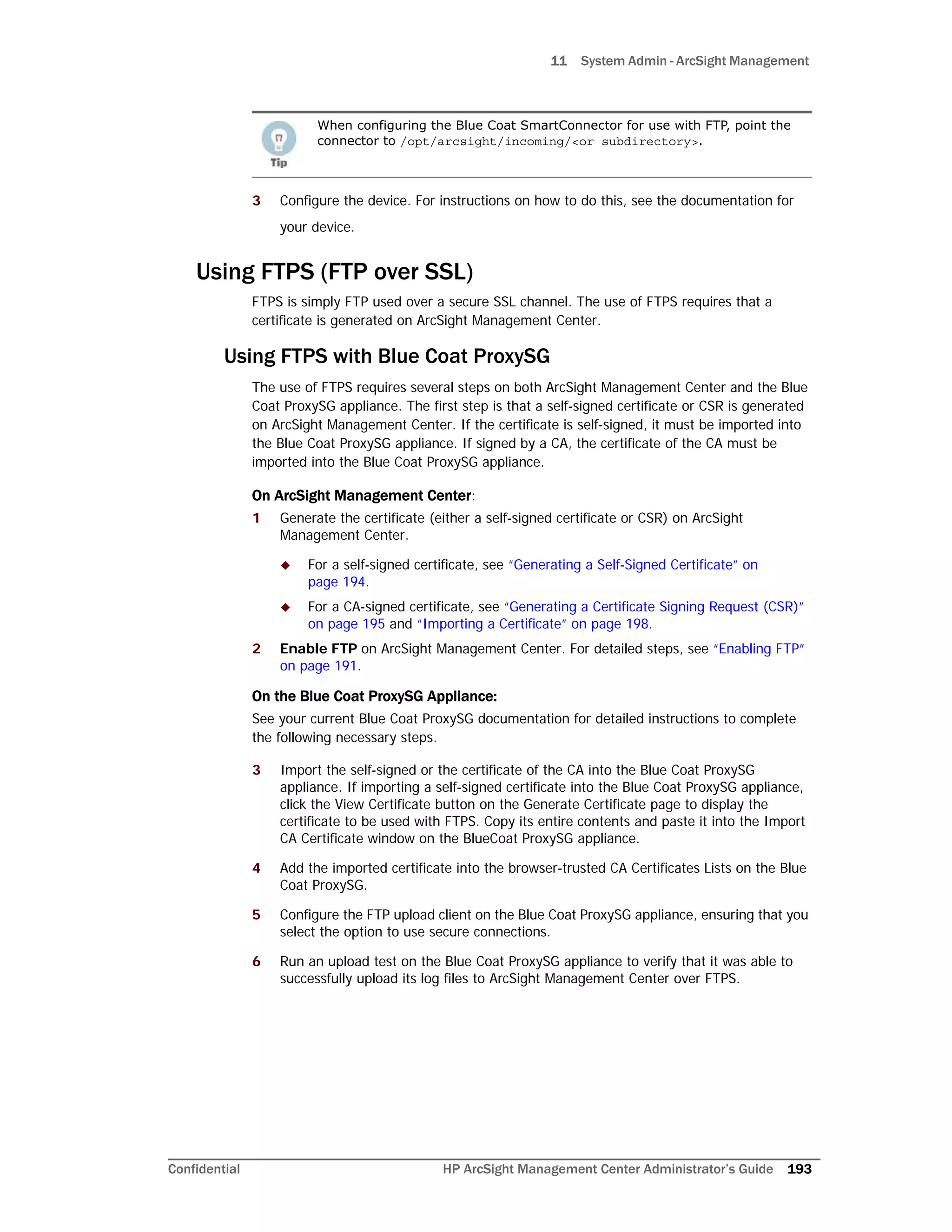
When configuring the Blue Coat SmartConnector for use with FTP, set up the
SmartConnector to delete files after processing. This step helps to prevent an
over accumulation of files on the FTP server.
To do so, in the agent.properties, change
agents[0].foldertable[0].mode=RenameInSameDirectory to
agents[0].foldertable[0].mode=DeleteFile.](https://image.slidesharecdn.com/arcmcadminguide1-170531062827/75/ArcSight-Management-Center-2-0-Administrator-s-Guide-194-2048.jpg)

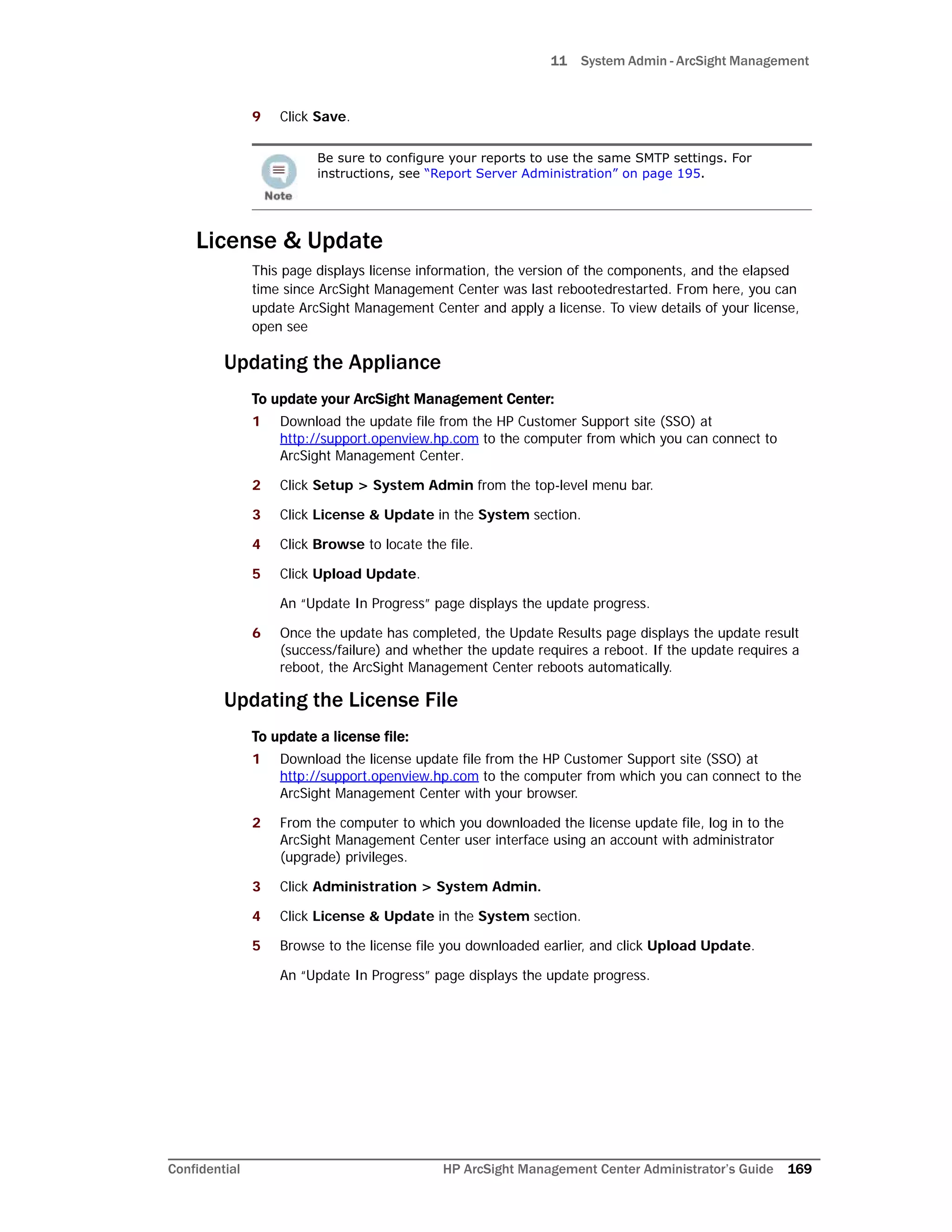
![11 System Admin - ArcSight Management Center
206 HP ArcSight Management Center Administrator’s Guide Confidential
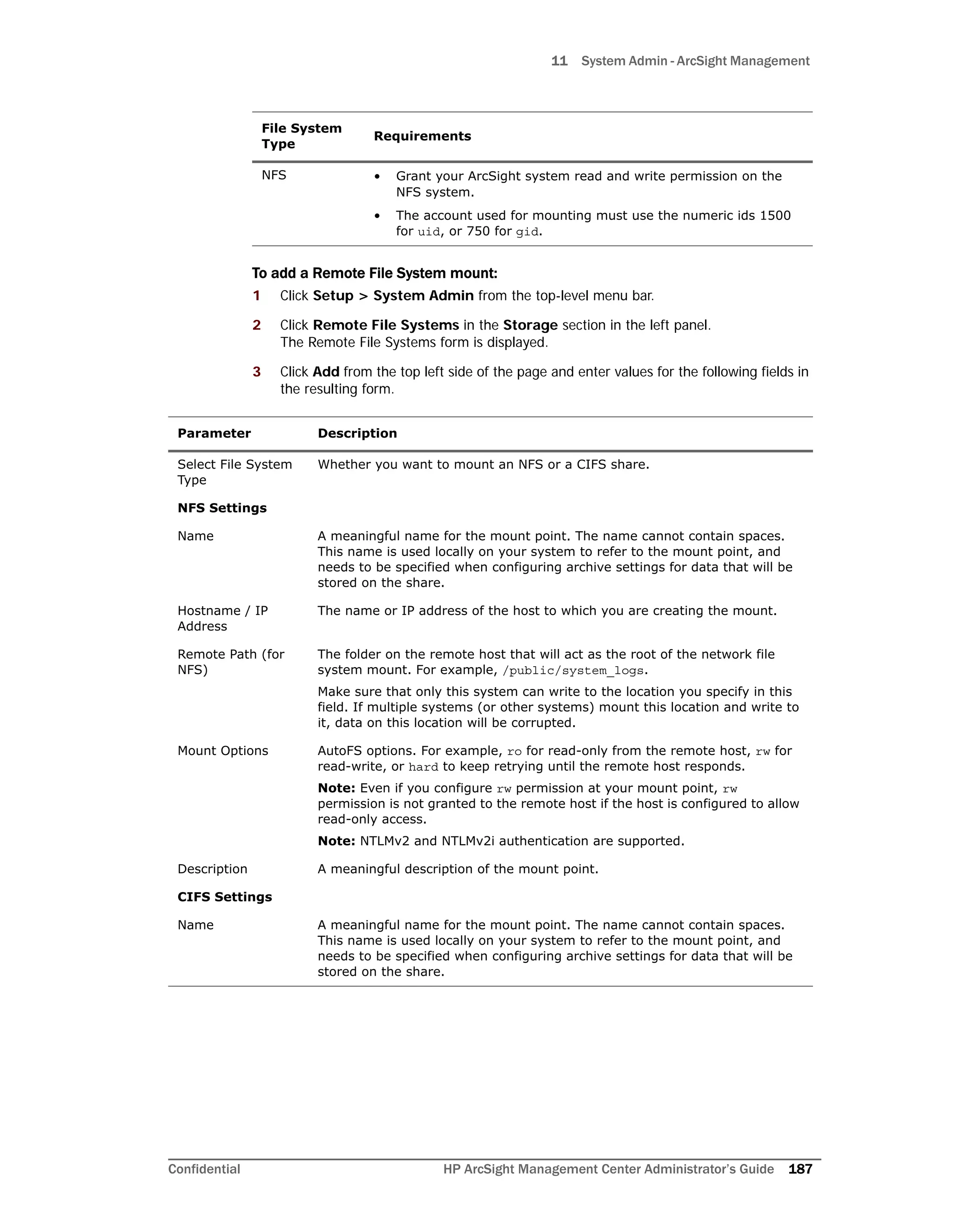
Distinguished Name (DN) specified for each user account must match the one in the LDAP
server.
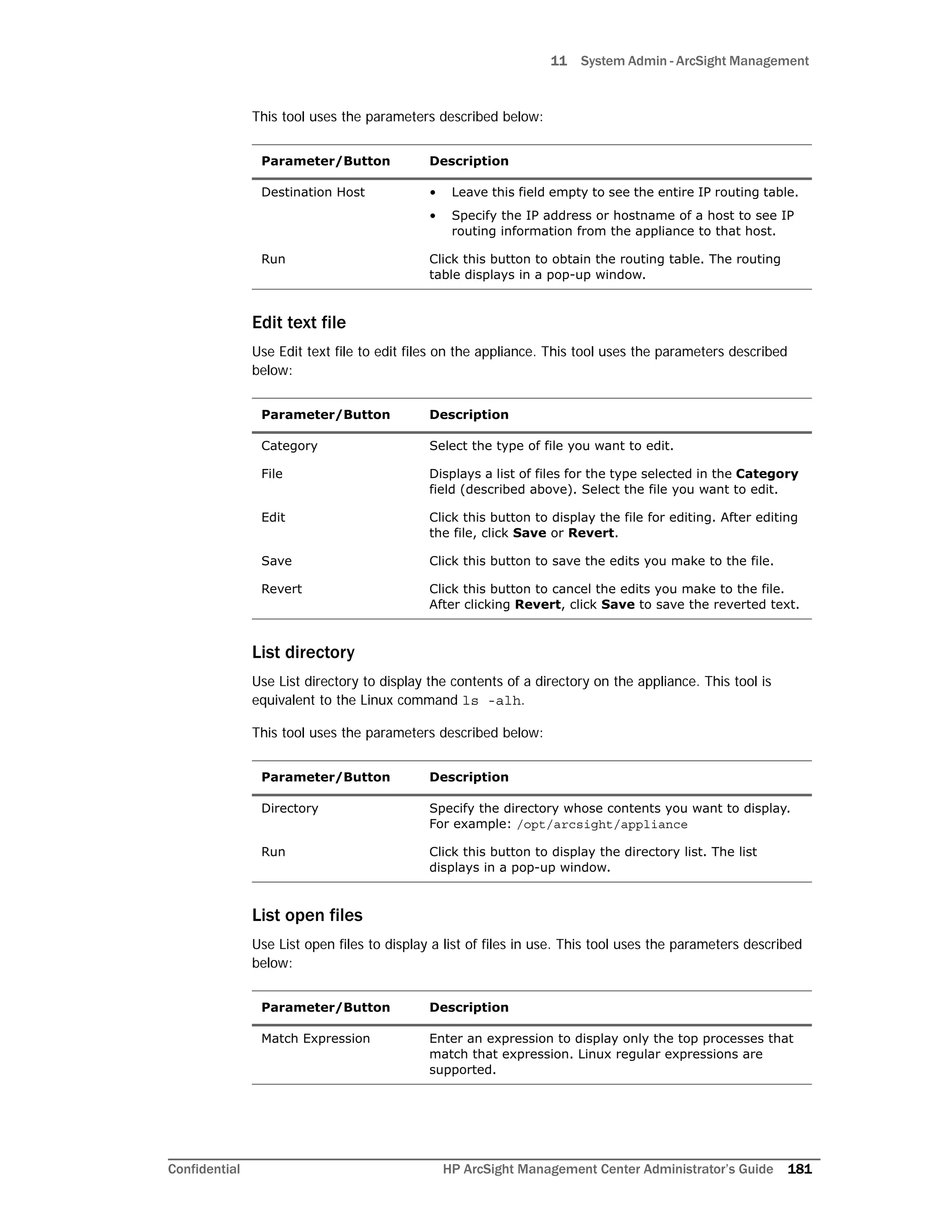
To set up LDAP authentication:
1 Click Administration > System Admin.
2 Click Authentication in the Users/Groups section.
3 Choose the External Authentication tab.
4 From the drop-down menu, choose LDAP.
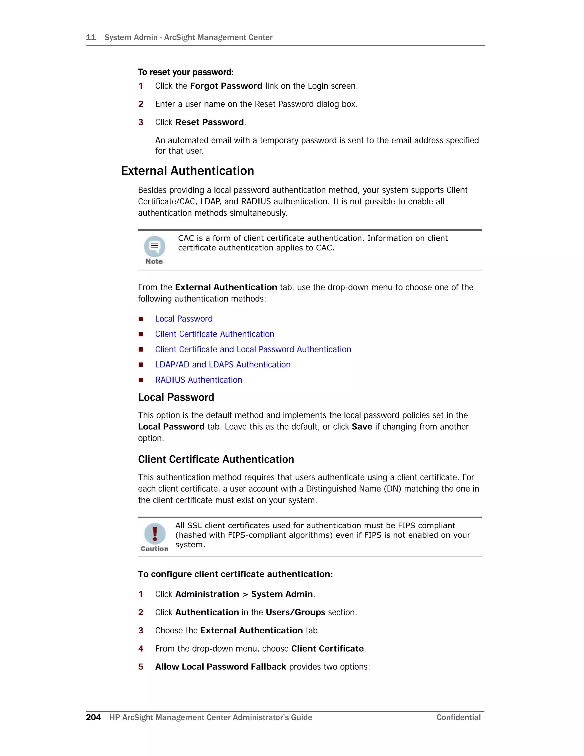
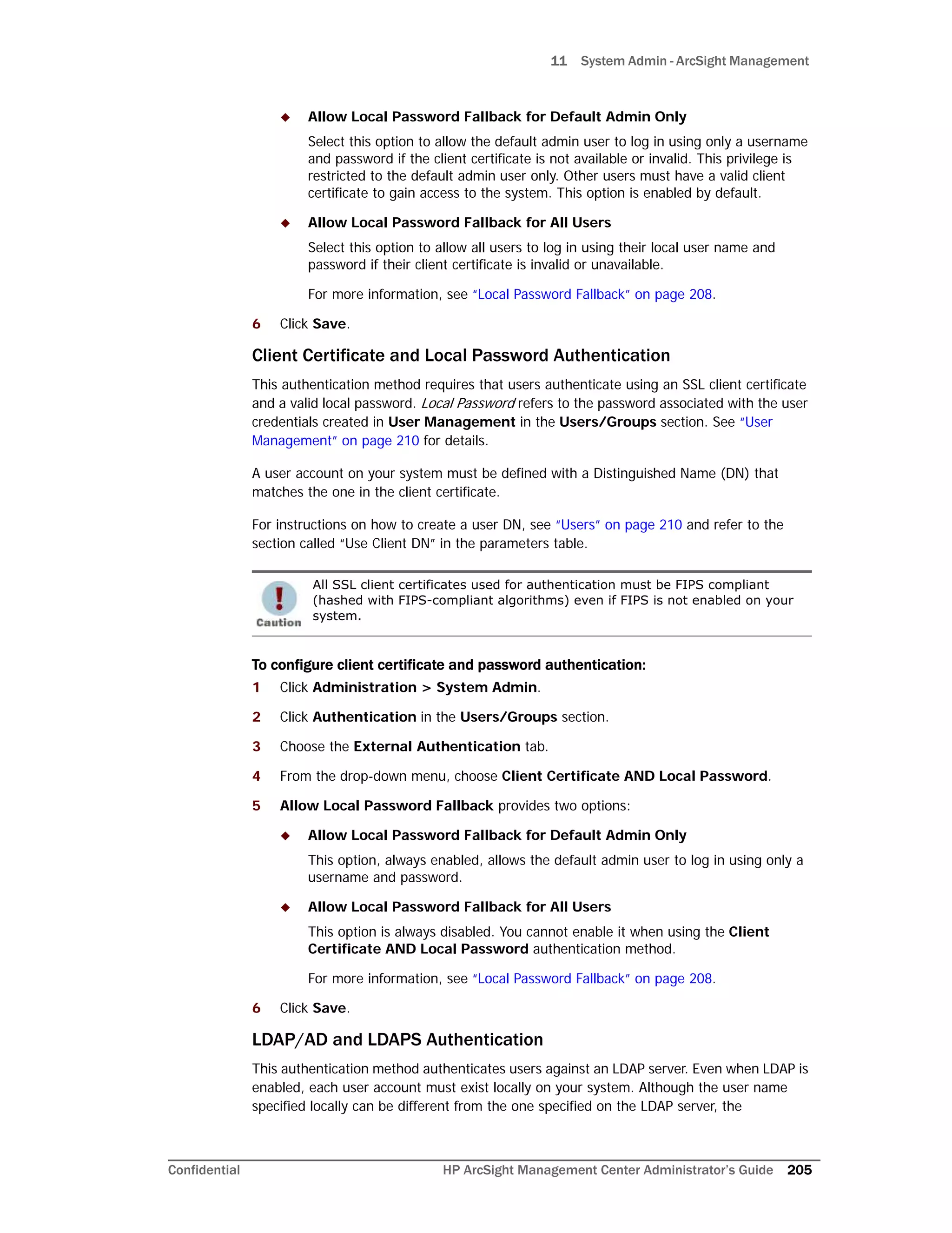
5 Allow Local Password Fallback provides two options:
Allow Local Password Fallback for Default Admin Only
Select this option to allow the default admin user to log in using only a username
and password if LDAP authentication fails. This privilege is restricted to the default
admin user only. All others must be authenticated by LDAP. This option is enabled
by default.
Allow Local Password Fallback for All Users
Select this option to allow all users to log in using their local user name and
password if LDAP authentication fails.
For more information, see “Local Password Fallback” on page 208.
LDAP Server has the following parameters:
6 When finished, click Save.
Using the LDAP over SSL (LDAPS) Protocol
When choosing the LDAPS protocol to authenticate users, make sure the following
conditions are true:
For steps on how to create a user DN, see “Users” on page 210, and the
parameter “Use Client DN” on page 210”.
Parameter Description
Server
Hostname[:port]
(optional)
(Optional) Enter the host name or IP address and port of the
LDAP server in the following format:
ldap://<hostname or IP address>:<port>
ldaps://<hostname or IP address>:<port>
Additional steps are required for the use of LDAPS. See Using
the LDAP over SSL (LDAPS) Protocol below.
Backup Server
Hostname[:Port]
(optional)
(Optional) Enter the backup LDAP server to use if the primary
server does not respond. If the server returns an authentication
failure (bad password, unknown username, etc), then the
backup server is not tried. The backup server is tried only when
the primary server has a communication failure.
Use the same format as the primary server to specify the host
name and port.
Request Timeout The length of time, in seconds, to wait for a response from the
LDAP server. The default is 10.](https://image.slidesharecdn.com/arcmcadminguide1-170531062827/75/ArcSight-Management-Center-2-0-Administrator-s-Guide-208-2048.jpg)
![11 System Admin - ArcSight Management
Confidential HP ArcSight Management Center Administrator’s Guide 207
The SSL certificate for the LDAPS server has been uploaded into the trusted store.
The external authentication method is set to “LDAP”.
The URL for the LDAPS server(s) starts with “ldaps://”.
After uploading the SSL certificate, restart the aps process (Setup >
System Admin > Process Status > aps Restart).
RADIUS Authentication
This authentication method allows users to authenticate against a RADIUS server. Even
when RADIUS authentication is enabled, each user account must exist locally on your
system. The username must match the one in the RADIUS server, although the password
can be different. A user must present a valid username and (RADIUS) password to be
successfully authenticated.
To configure RADIUS authentication settings:
1 Click Administration > System Admin.
2 Click Authentication in the Users/Groups section.
3 Choose the External Authentication tab.
4 From the drop-down menu, choose RADIUS.
5 Allow Local Password Fallback provides two options:
Allow Local Password Fallback for Default Admin Only
Select this option to allow the default admin user to log in using only a username
and password if RADIUS authentication fails. This privilege is restricted to the
admin user only. All others must be authenticated by RADIUS. This option is
enabled by default.
Allow Local Password Fallback for All Users
Select this option to allow all users to log in using their local user name and
password, if RADIUS authentication fails. For more information, see “Local
Password Fallback” on page 208.
6 Update the RADIUS Server parameters as necessary:
If the aps process is not restarted, attempts to authenticate using LDAPS will
fail.
Parameter Description
Server
Hostname[:port]
Enter the host name and port of the RADIUS server.
Backup Server
hostname[:port]
(optional)
(Optional) Enter the backup RADIUS server to use if the
primary server does not respond. If the server returns an
authentication failure (bad password, unknown username,
etc), then the backup server is not tried. The backup server
is tried only when the primary server has a communication
failure.
Use the same format as the primary server to specify the
host name and port.](https://image.slidesharecdn.com/arcmcadminguide1-170531062827/75/ArcSight-Management-Center-2-0-Administrator-s-Guide-209-2048.jpg)

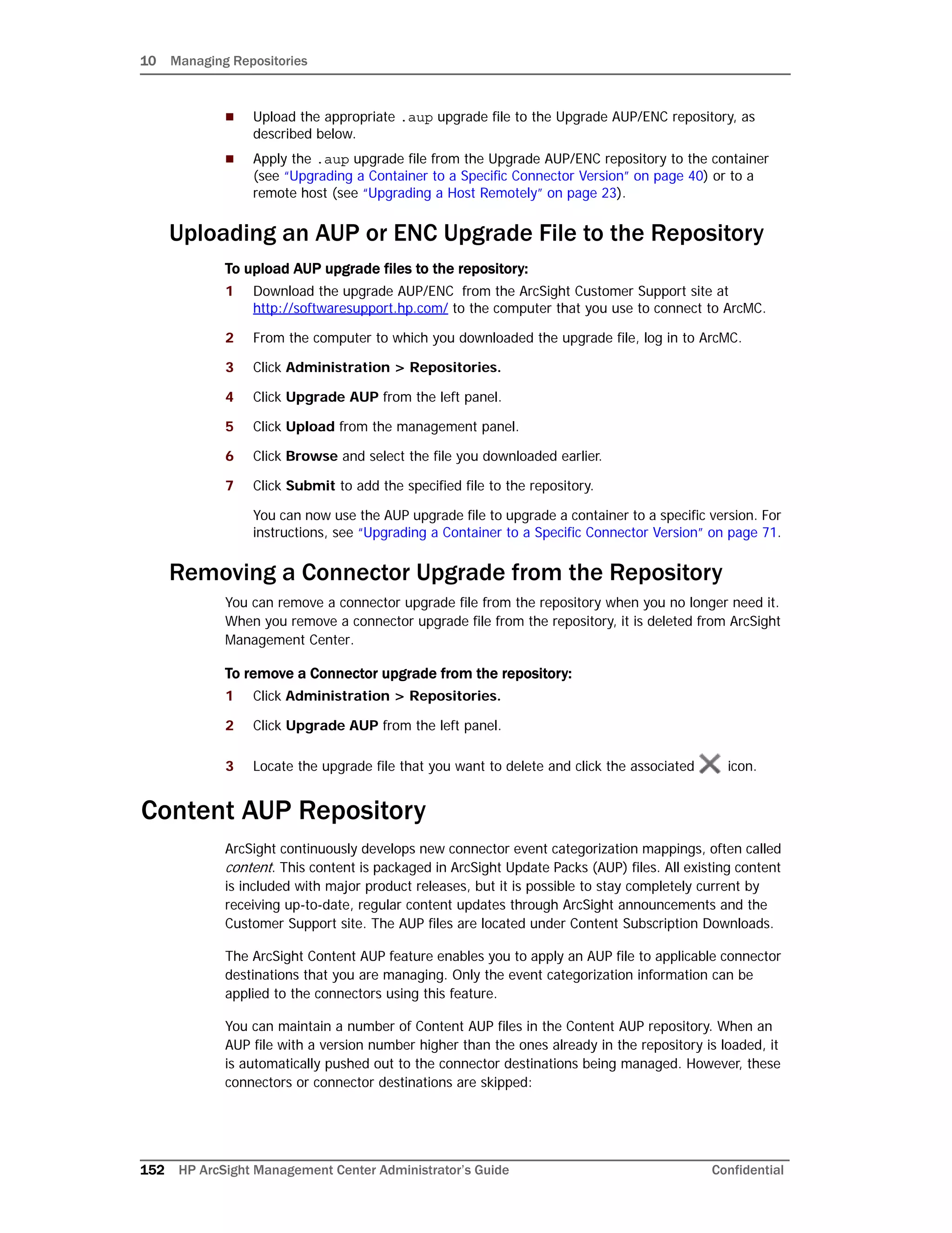
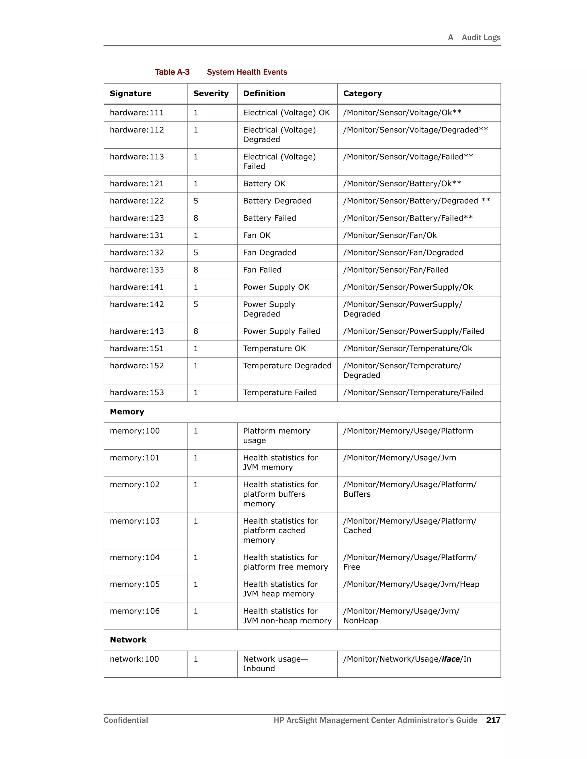
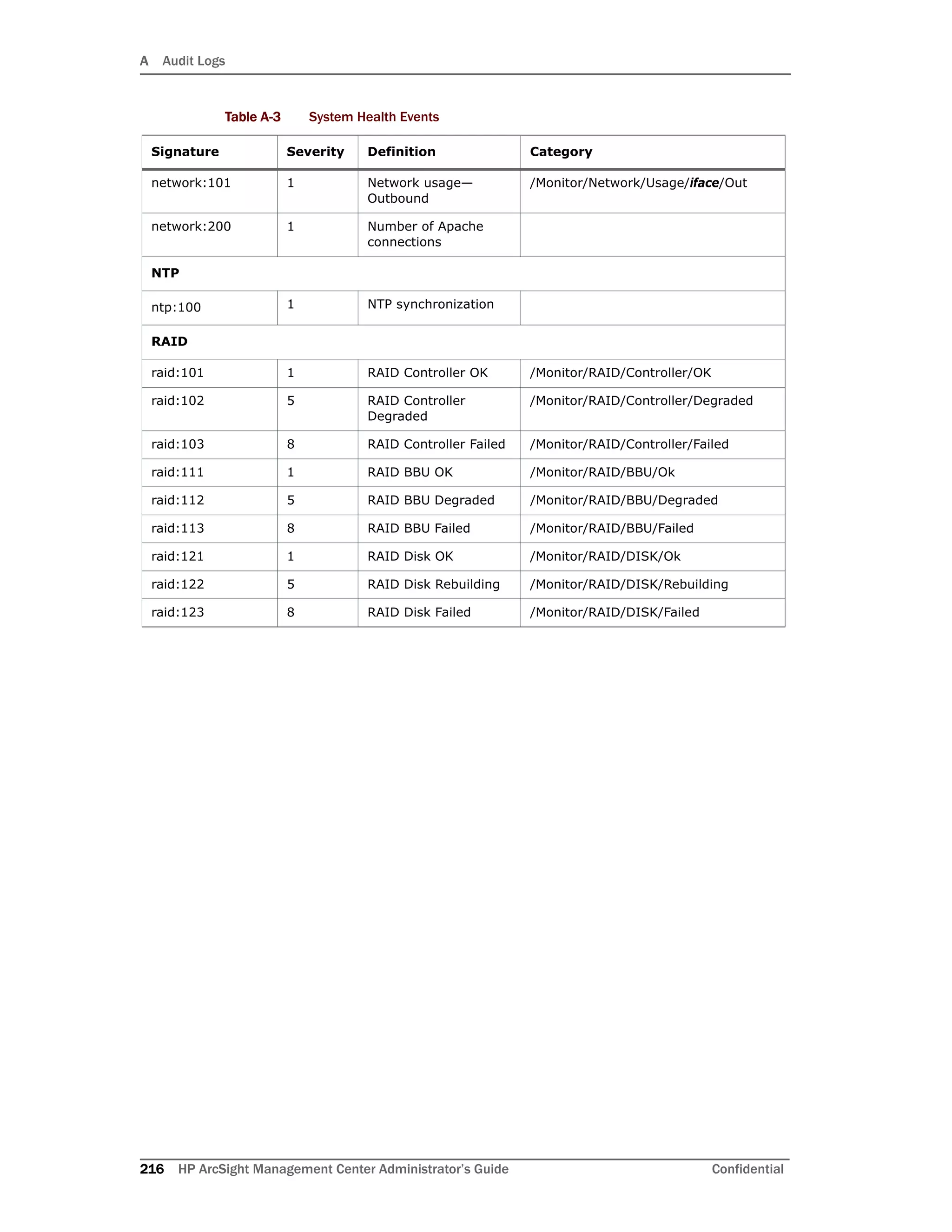
![A Audit Logs
Confidential HP ArcSight Management Center Administrator’s Guide 217
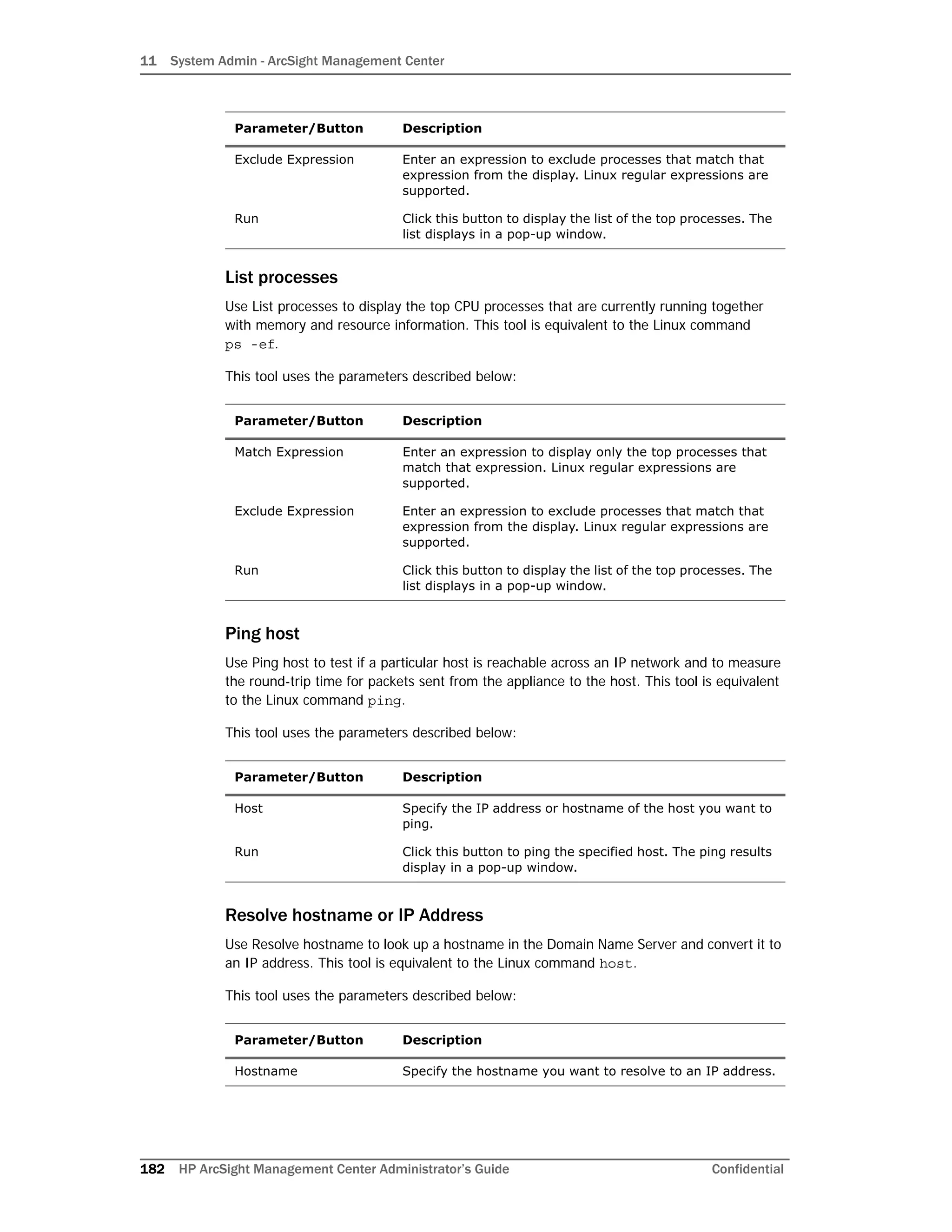
Container
container:101 1 Container upgrade
successful
/Container/Upgrade/Success
container:102 1 Push user file
successful
/Container/UserFiles/Push/
Success
container:103 1 User file delete from
container
/Container/UserFiles/Delete
container:104 1 CA cert push to a
container successful
/Container/CACert/Push/
Success
container:105 1 Container demo CA
enable successful
/Container/DemoCA/Enable/
Success
container:106 1 Container demo CA
disable successfu
/Container/DemoCA/Disable/
Success
container:109 1 Delete property from a
container successful
/Container/Property/Delete/Suc
cess
container:110 1 Modify properties
successful
/Container/Property/Update/Suc
cess
container:111 1 Container password
update successful
/Container/Password/Update/
Success
container:113 1 Container edit /Container/Update
container:114 1 Remove container /Container/Delete
container:115 1 Add certificate for a
container successful
/Container/Certificate/Add/
Success
container:116 1 Removing certificates
successful [addtrust
class 1ca]
/Container/Certificate/Delete/
Success
container:117 1 Enabling FIPS mode
successful
/Container/FIPS/Enable/Success
container:118 1 Disabling FIPS mode
successful
/Container/FIPS/Disable/
Success
container:119 1 Upgrade was triggered
for container that
resides on end of life
appliance model
Container/FromEndOfLifeModel/
Upgrade/Triggered
container:201 1 Container upgrade
failed
/Container/Upgrade/Fail
container:202 1 User file push to a
container failed
/Container/UserFiles/Push/Fail
container:204 1 CA cert push to a
container failed
/Container/CACert/Push/Fail
container:205 1 Enable demo CA for a
container failed
/Container/DemoCA/Enable/Fail
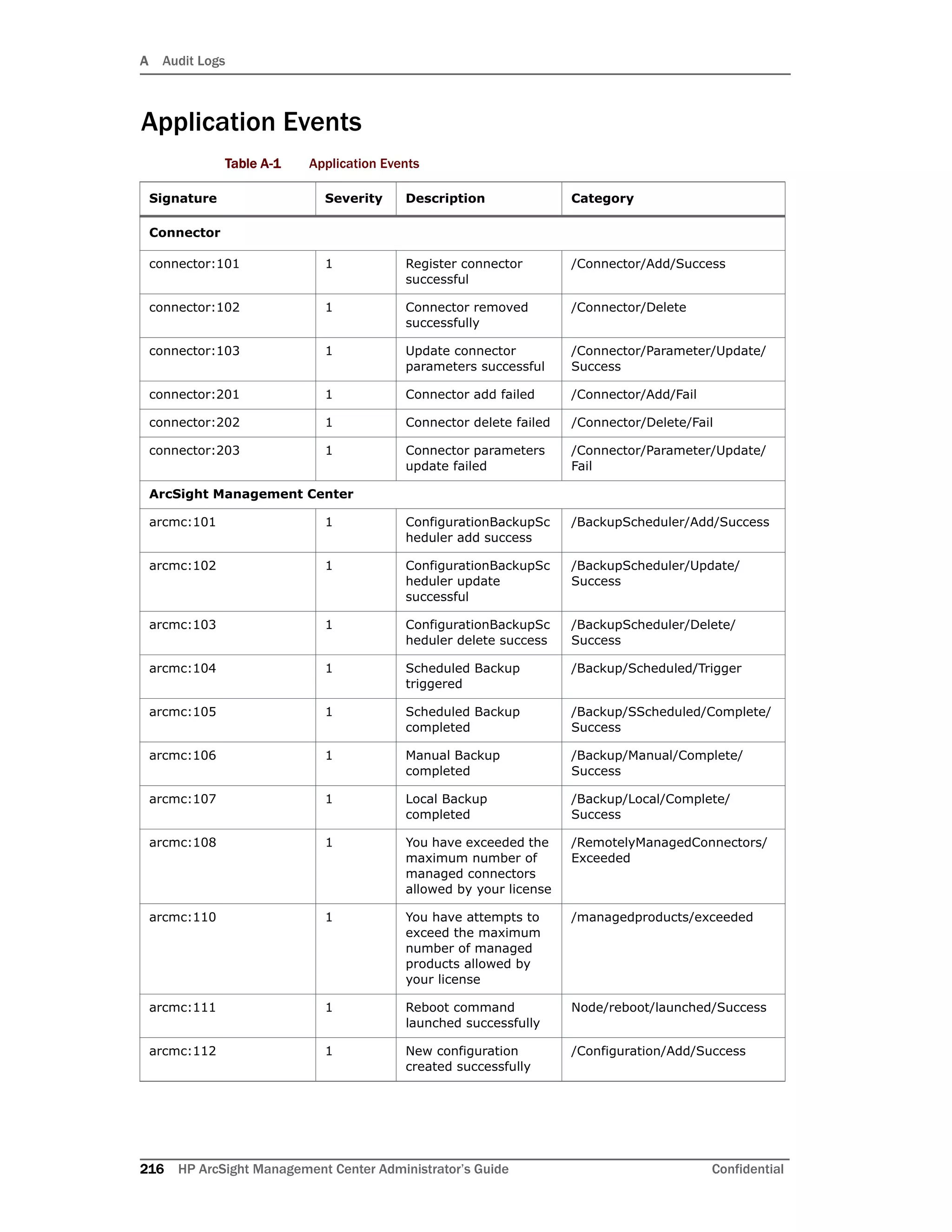
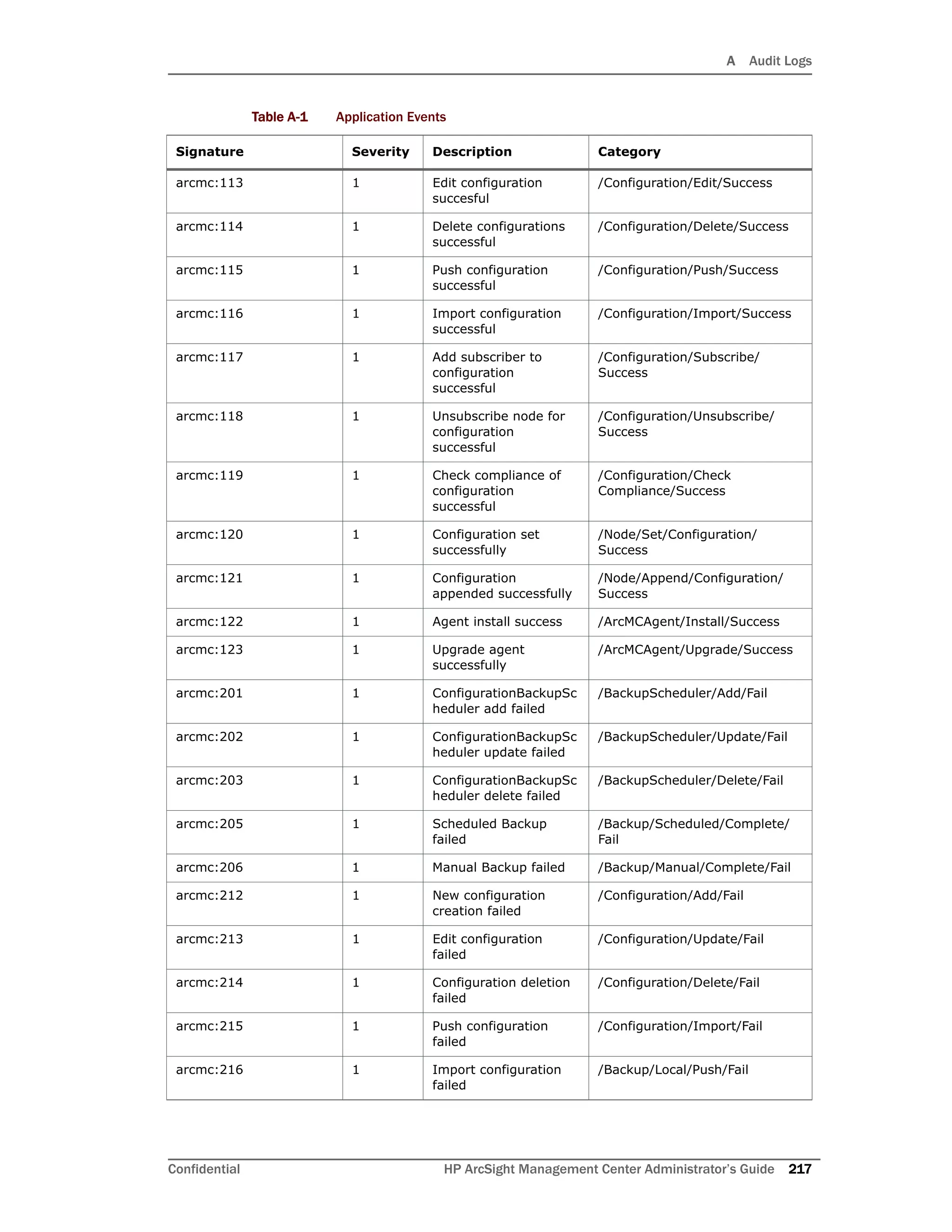
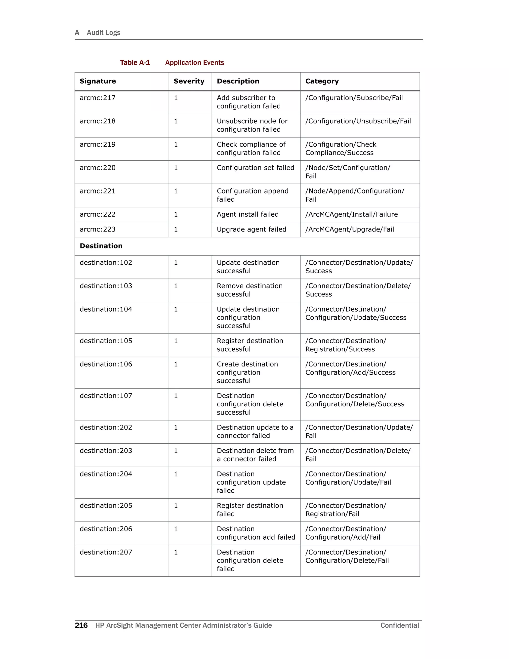
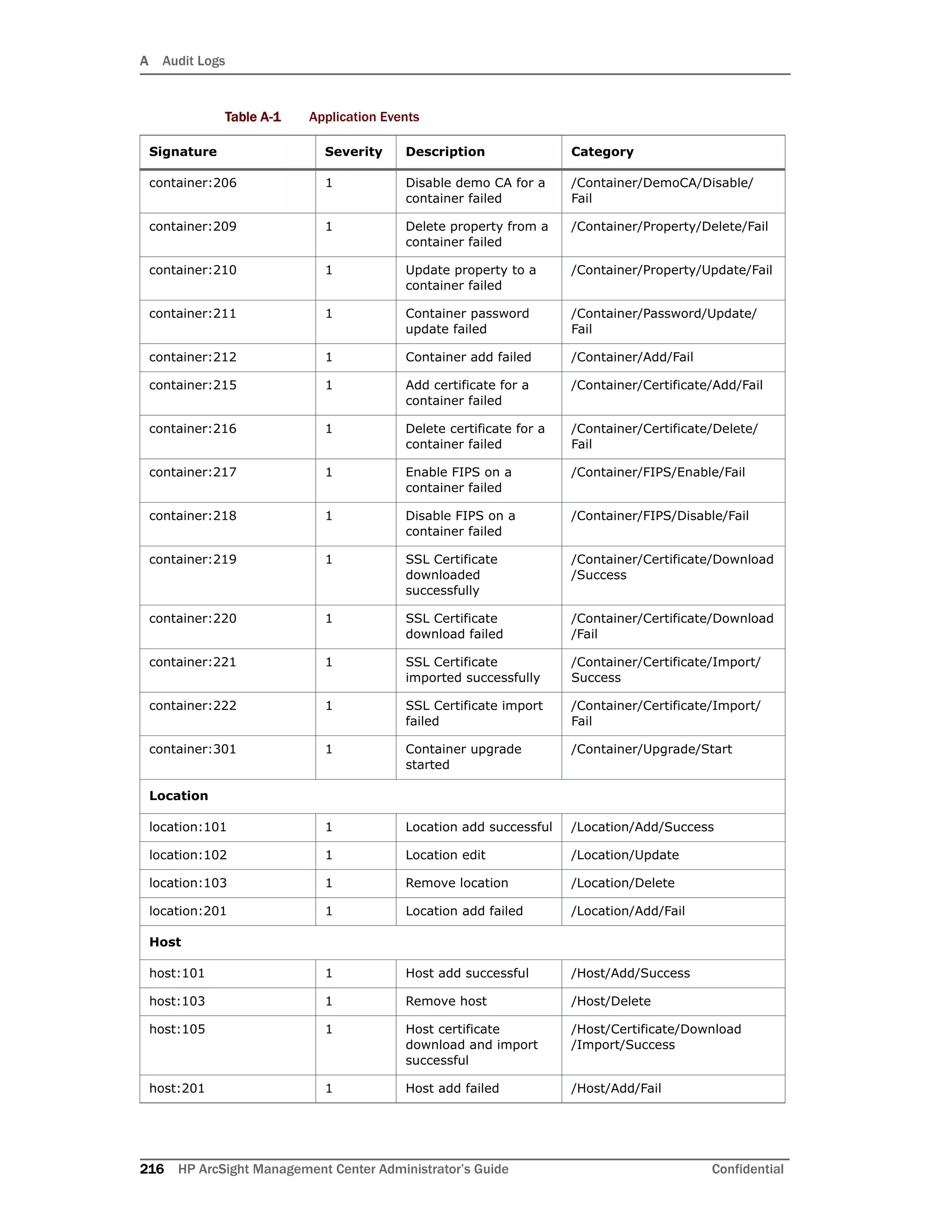
Table A-1 Application Events
Signature Severity Description Category](https://image.slidesharecdn.com/arcmcadminguide1-170531062827/75/ArcSight-Management-Center-2-0-Administrator-s-Guide-221-2048.jpg)


![C Special Connector Configurations
Confidential HP ArcSight Management Center Administrator’s Guide 239
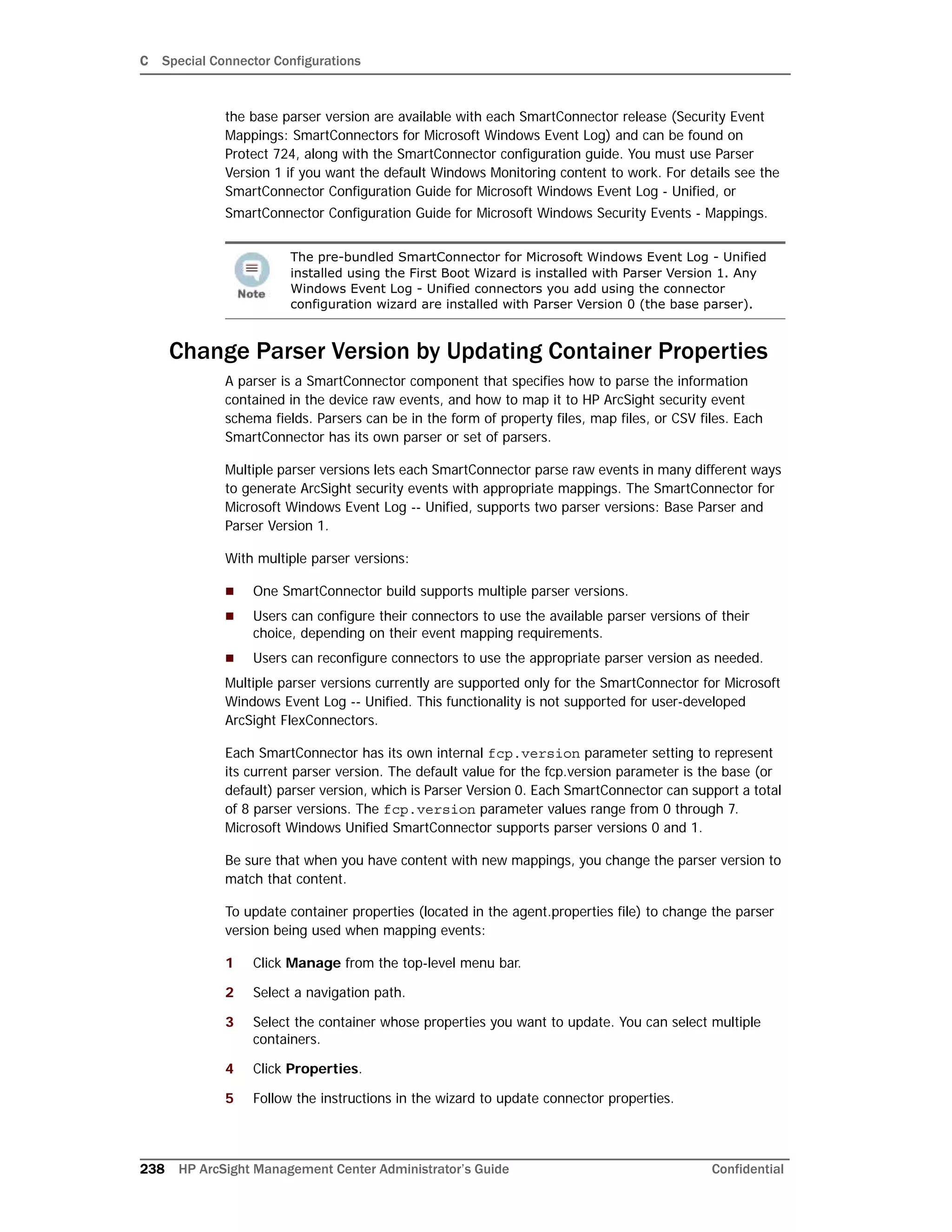
The fcp.version parameter value 0 designates the base parser. To use parser 1,
change the fcp.version parameter value to 1. For example:
agents[0].fcp.version=1
SSL Authentication
If you choose to use SSL as the connection protocol, you must add security certificates for
both the Windows Domain Controller Service and for the Active Directory Server. Installing
a valid certificate on a domain controller permits the LDAP service to listen for, and
automatically accept, SSL connections for both LDAP and global catalog traffic. With the
First Boot Wizard installation of the connector, the certificates are already imported for you.
If you add Windows Event Log - Unified connectors, see the SmartConnector Configuration
Guide for Microsoft Windows Event Log - Unified for instructions.
Database Connectors
The following database connectors are available for installation with ArcSight Management
Center:
IBM SiteProtector DB*
McAfee ePolicy Orchestrator DB*
McAfee Vulnerability Manager DB*
McAfee Network Security Manager DB*
Microsoft SQL Server Audit Multiple Instance DB*
Oracle Audit DB
Symantec Endpoint Protection DB*
Trend Micro Control Manager NG DB*
Snort DB*
*These connectors extract events from an SQL Server or MySQL databases, which requires
a JDBC driver. See “Add a JDBC Driver” on page 240 for instructions.
All of these database connectors require the following information when being added to
ArcSight Management Center; some connectors require additional parameters, such as
event types or polling frequency.
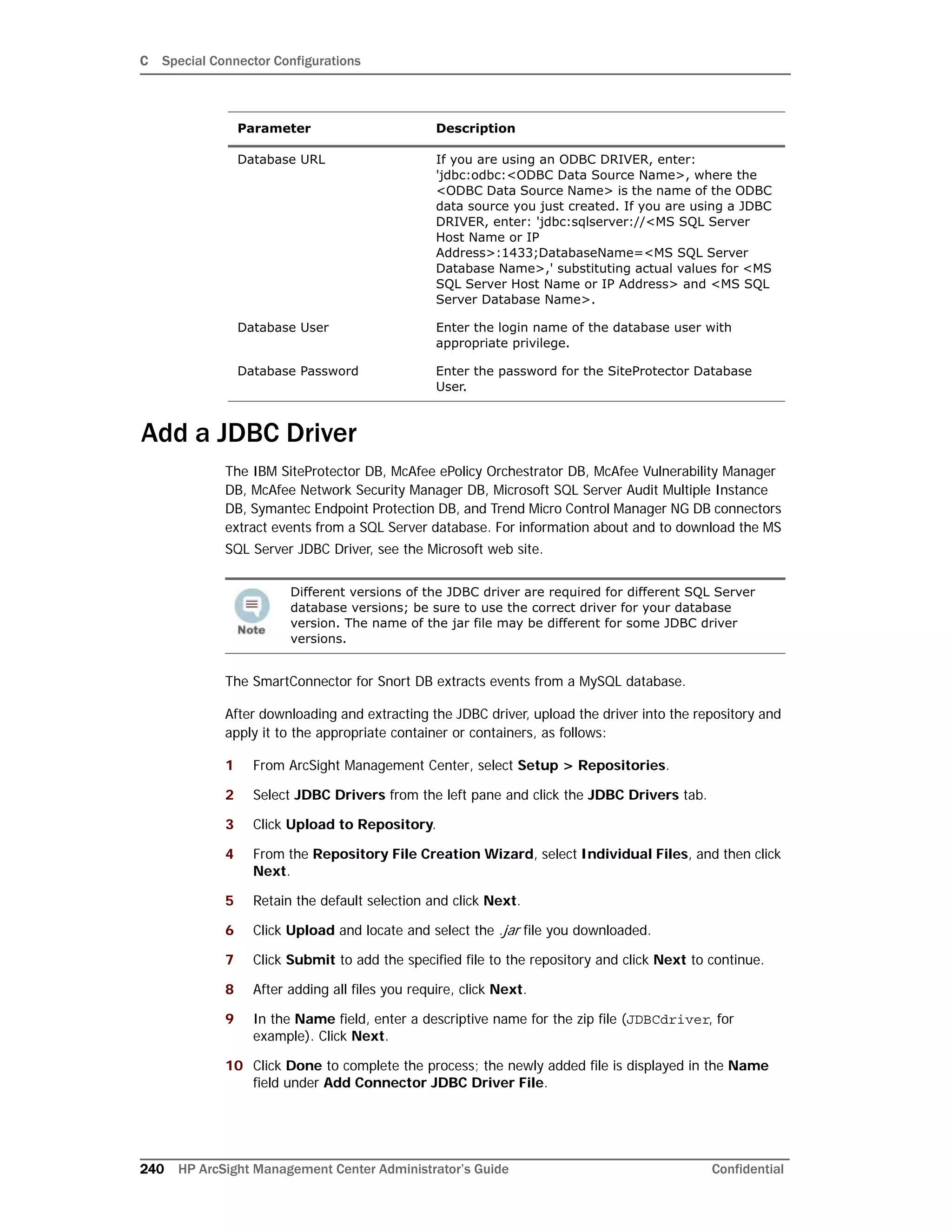
Parameter Description
Database JDBC Driver If you are using an ODBC DRIVER, select
'sun.jdbc.odbc.JdbcOdbcDriver' driver. For JDBC
drivers, select the
'com.microsoft.sqlserver.jdbc.SQLServerDriver' driver.
If you are using an ODBC DRIVER, select
'sun.jdbc.odbc.JdbcOdbcDriver' driver. For JDBC
drivers, select the
'com.microsoft.sqlserver.jdbc.SQLServerDriver' driver.](https://image.slidesharecdn.com/arcmcadminguide1-170531062827/75/ArcSight-Management-Center-2-0-Administrator-s-Guide-241-2048.jpg)