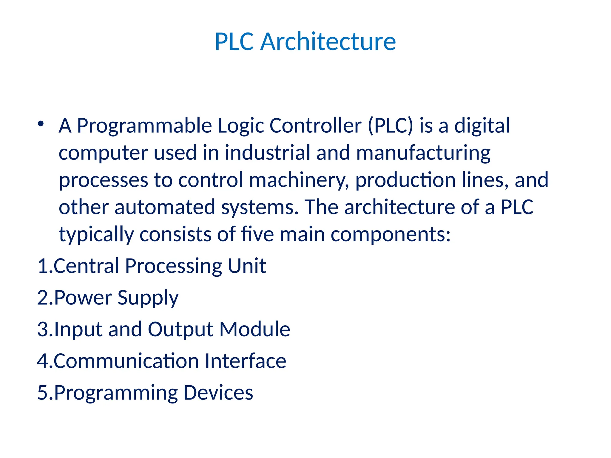
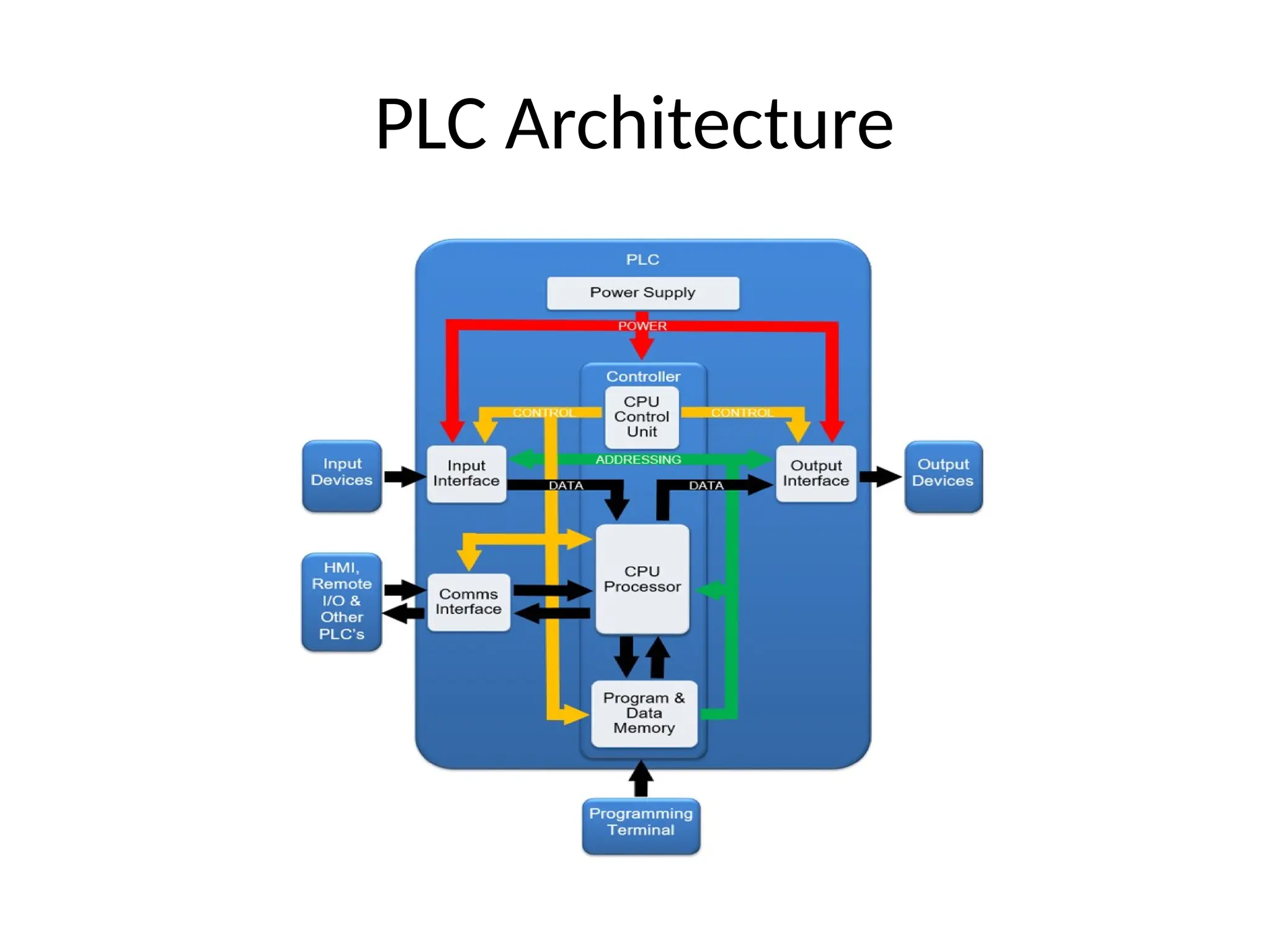
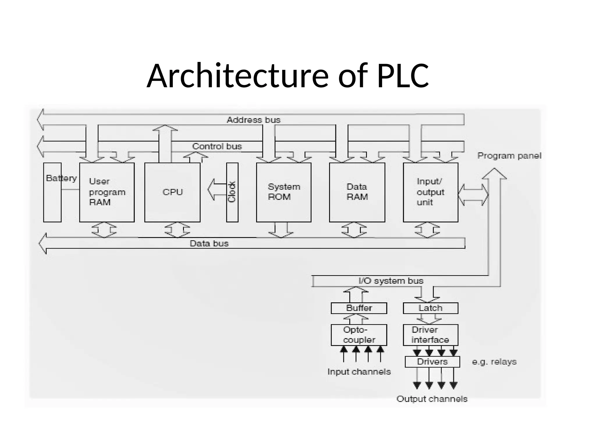
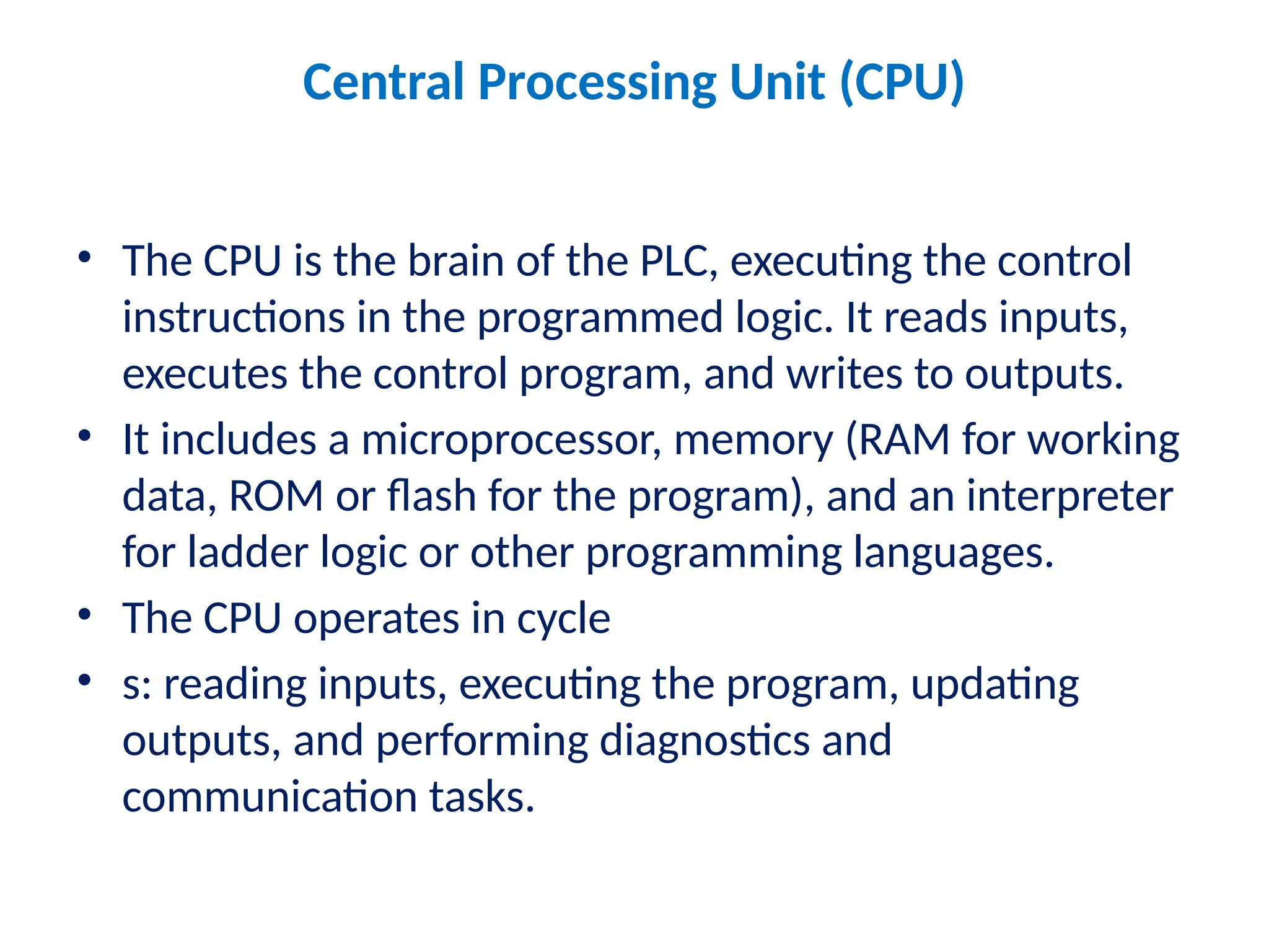
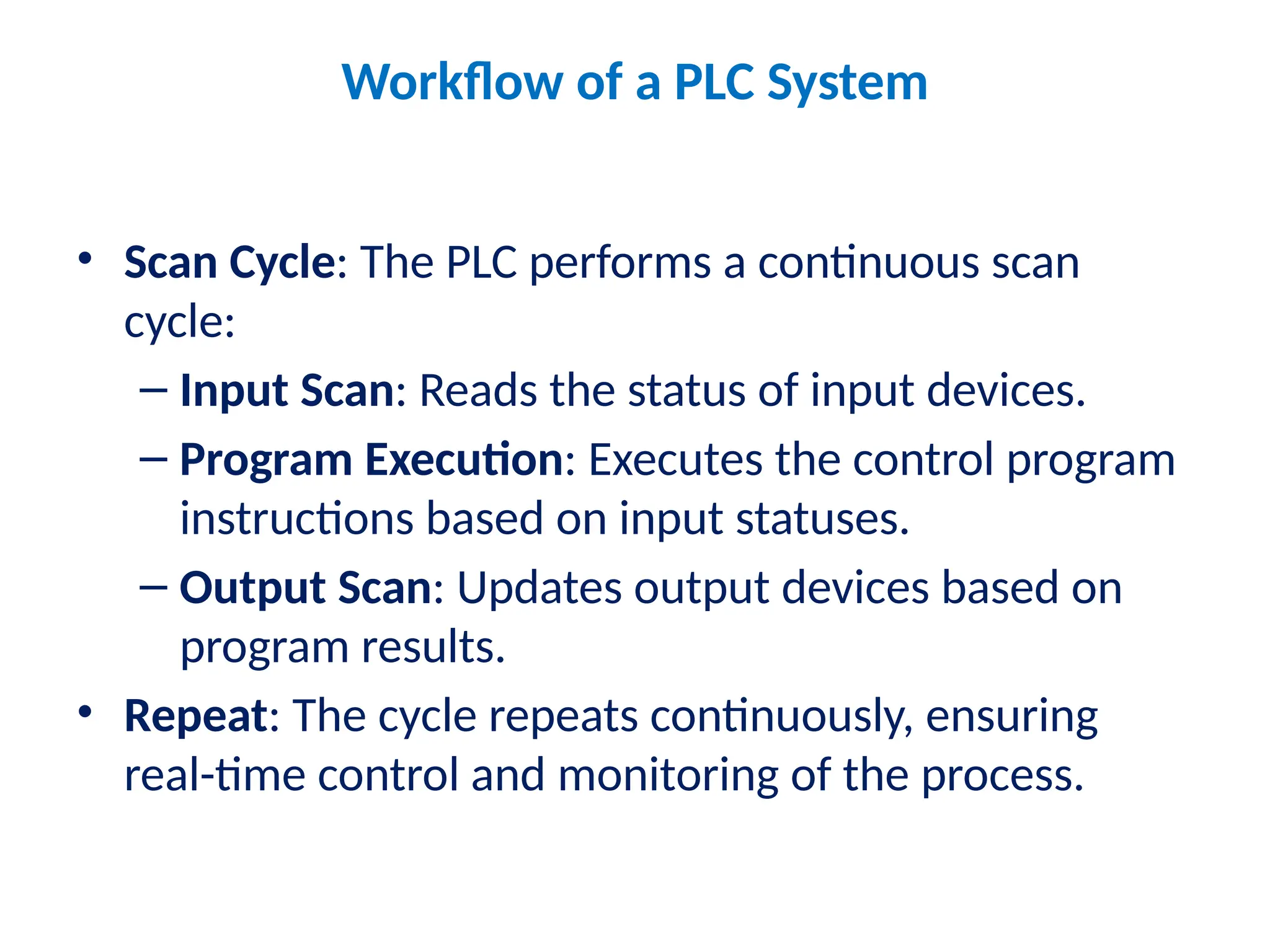
PLC Architecture
• A Programmable Logic Controller (PLC) is a digital
computer used in industrial and manufacturing
processes to control machinery, production lines, and
other automated systems. The architecture of a PLC
typically consists of five main components:
1.Central Processing Unit
2.Power Supply
3.Input and Output Module
4.Communication Interface
5.Programming Devices
PLC Architecture
Architecture of PLC
Central Processing Unit (CPU)
• The CPU is the brain of the PLC, executing the control
instructions in the programmed logic. It reads inputs,
executes the control program, and writes to outputs.
• It includes a microprocessor, memory (RAM for working
data, ROM or flash for the program), and an interpreter
for ladder logic or other programming languages.
• The CPU operates in cycle
• s: reading inputs, executing the program, updating
outputs, and performing diagnostics and
communication tasks.
Power Supply
• The power supply module provides the necessary DC
power to other PLC modules (e.g., CPU, I/O
modules).
• It usually converts standard AC voltage to the DC
voltage level required by the PLC and may offer some
power conditioning and protection.
Input/Output (I/O) Modules
• The I/O modules serve as the interface between the
PLC and external devices, allowing it to monitor and
control equipment.
• Input modules receive signals from sensors or other
input devices (e.g., switches, proximity sensors).
• Output modules send control signals to actuators or
other output devices (e.g., motors, relays, solenoids)
Communication Interface
• PLCs often include communication interfaces for
networking, which allow them to connect to other
PLCs, SCADA systems, HMIs, or other control
systems.
• Communication can occur via various protocols, such
as Ethernet/IP, Modbus, or Profinet, depending on
the industrial environment and requirements.
Programming Device
• The programming device (e.g., PC or dedicated
programming console) is used to create and modify
the control program.
• Programs are written in PLC-specific programming
languages, such as Ladder Logic, Function Block
Diagrams, or Structured Text, which the CPU
executes.
Workflow of a PLC System
• Scan Cycle: The PLC performs a continuous scan
cycle:
– Input Scan: Reads the status of input devices.
– Program Execution: Executes the control program
instructions based on input statuses.
– Output Scan: Updates output devices based on
program results.
• Repeat: The cycle repeats continuously, ensuring
real-time control and monitoring of the process.

Architecture and working of of PLC and applicatons

  • 1.
    PLC Architecture • AProgrammable Logic Controller (PLC) is a digital computer used in industrial and manufacturing processes to control machinery, production lines, and other automated systems. The architecture of a PLC typically consists of five main components: 1.Central Processing Unit 2.Power Supply 3.Input and Output Module 4.Communication Interface 5.Programming Devices
  • 2.
  • 3.
  • 4.
    Central Processing Unit(CPU) • The CPU is the brain of the PLC, executing the control instructions in the programmed logic. It reads inputs, executes the control program, and writes to outputs. • It includes a microprocessor, memory (RAM for working data, ROM or flash for the program), and an interpreter for ladder logic or other programming languages. • The CPU operates in cycle • s: reading inputs, executing the program, updating outputs, and performing diagnostics and communication tasks.
  • 5.
    Power Supply • Thepower supply module provides the necessary DC power to other PLC modules (e.g., CPU, I/O modules). • It usually converts standard AC voltage to the DC voltage level required by the PLC and may offer some power conditioning and protection.
  • 6.
    Input/Output (I/O) Modules •The I/O modules serve as the interface between the PLC and external devices, allowing it to monitor and control equipment. • Input modules receive signals from sensors or other input devices (e.g., switches, proximity sensors). • Output modules send control signals to actuators or other output devices (e.g., motors, relays, solenoids)
  • 7.
    Communication Interface • PLCsoften include communication interfaces for networking, which allow them to connect to other PLCs, SCADA systems, HMIs, or other control systems. • Communication can occur via various protocols, such as Ethernet/IP, Modbus, or Profinet, depending on the industrial environment and requirements.
  • 8.
    Programming Device • Theprogramming device (e.g., PC or dedicated programming console) is used to create and modify the control program. • Programs are written in PLC-specific programming languages, such as Ladder Logic, Function Block Diagrams, or Structured Text, which the CPU executes.
  • 9.
    Workflow of aPLC System • Scan Cycle: The PLC performs a continuous scan cycle: – Input Scan: Reads the status of input devices. – Program Execution: Executes the control program instructions based on input statuses. – Output Scan: Updates output devices based on program results. • Repeat: The cycle repeats continuously, ensuring real-time control and monitoring of the process.