Download as PDF, PPTX

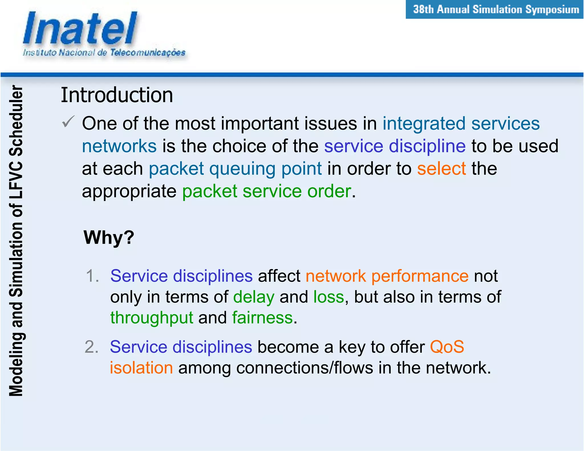
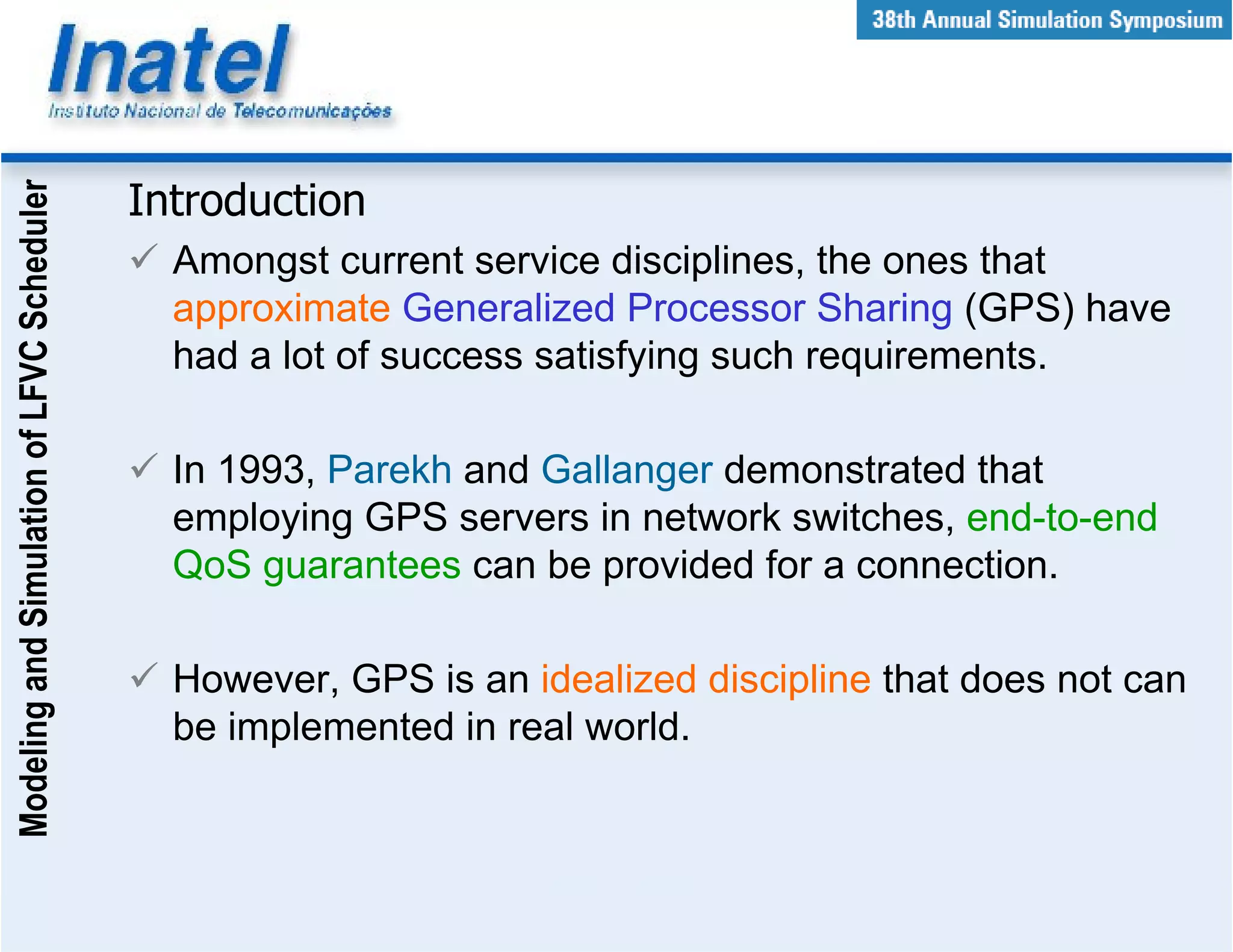

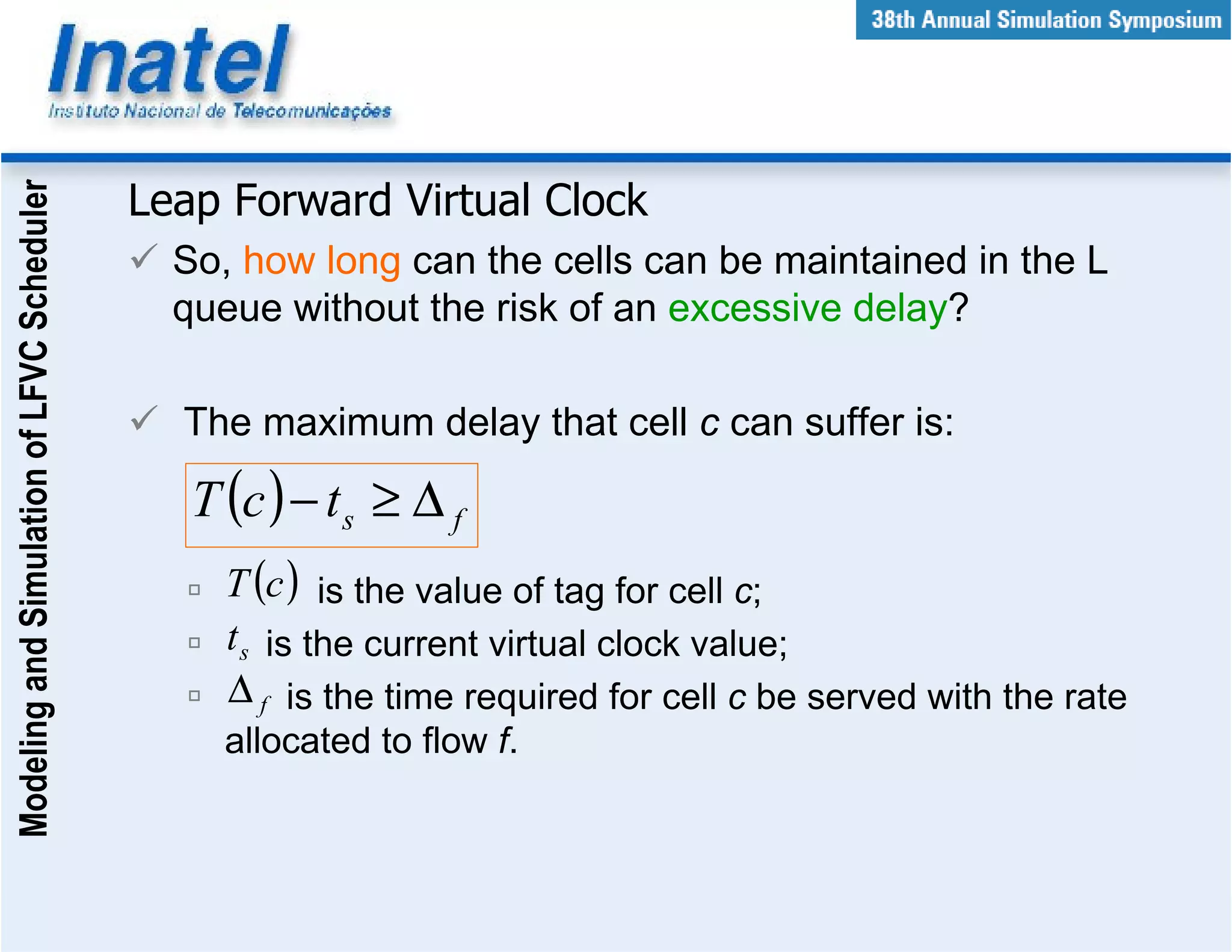
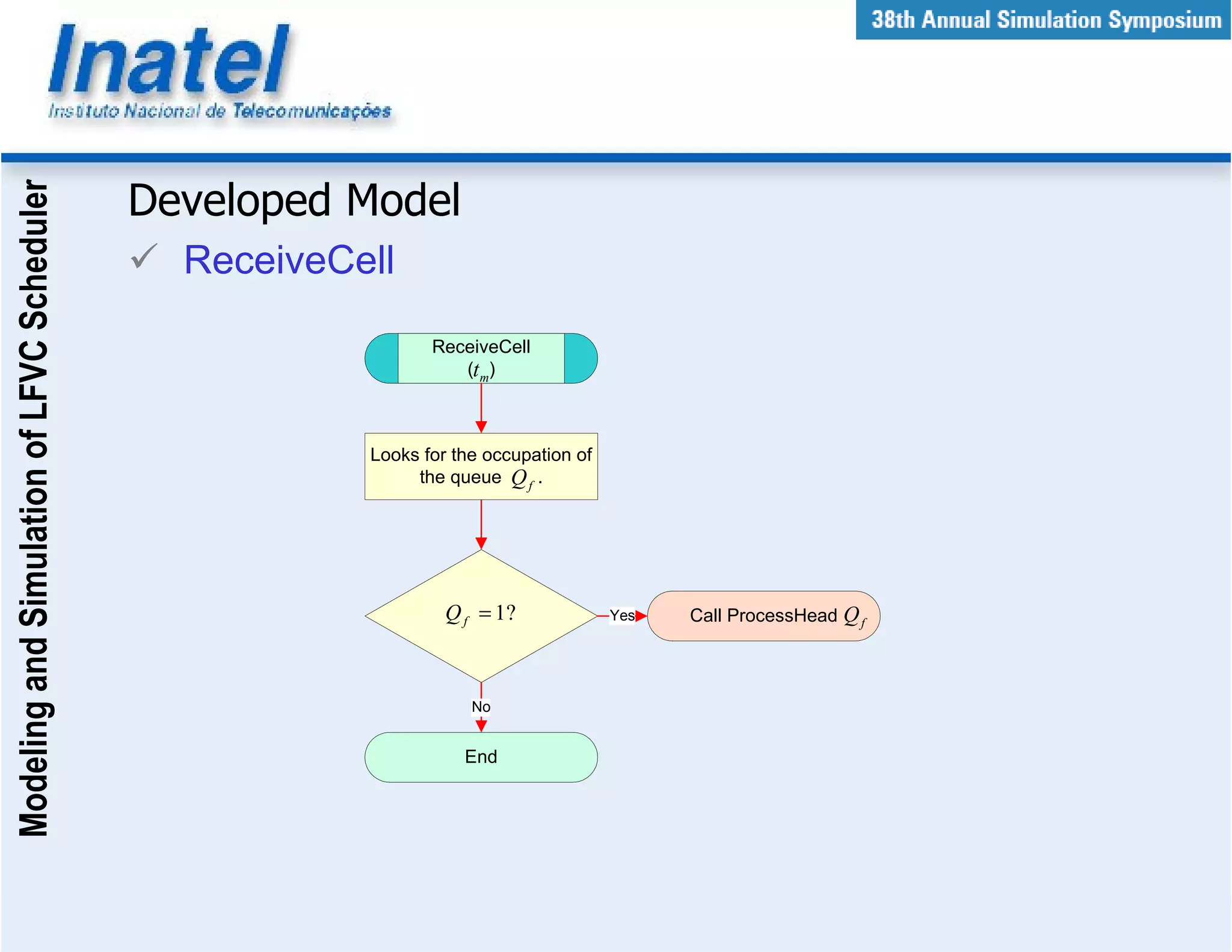
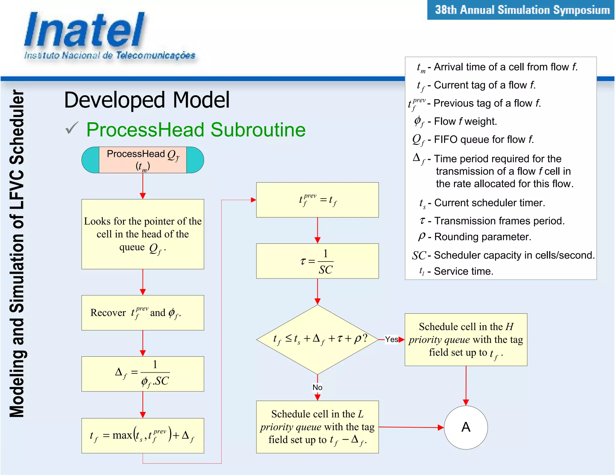
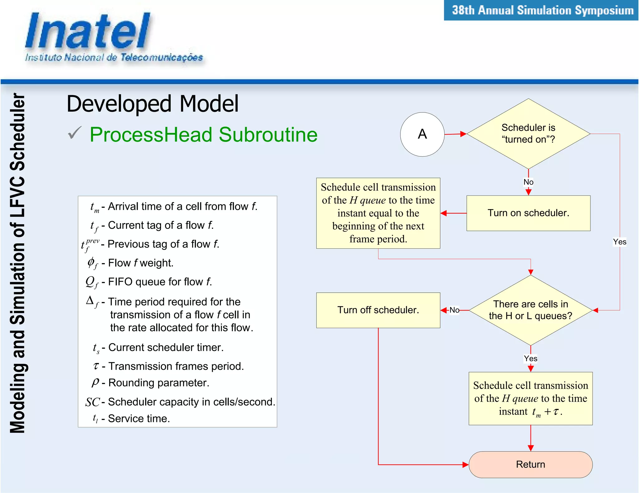
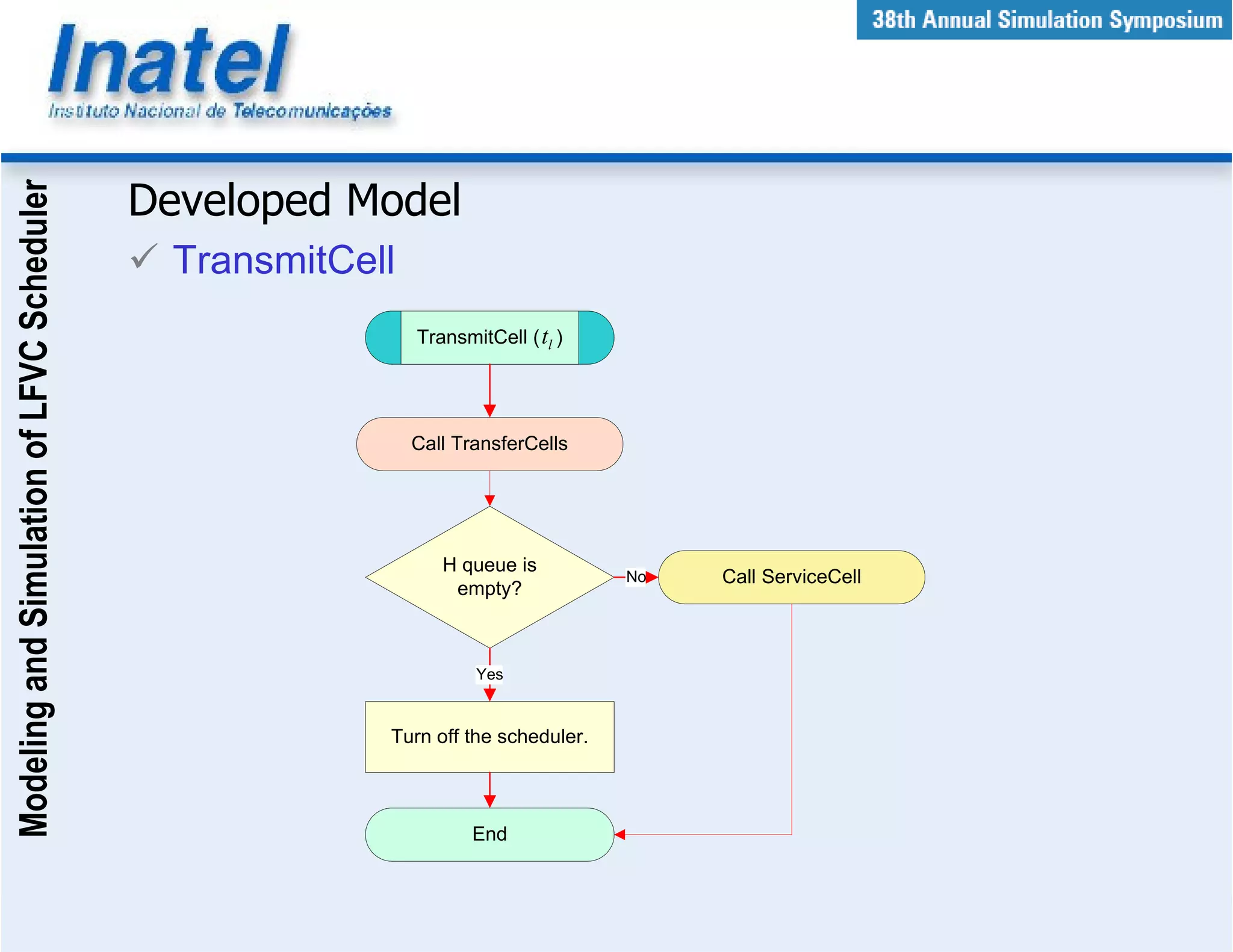
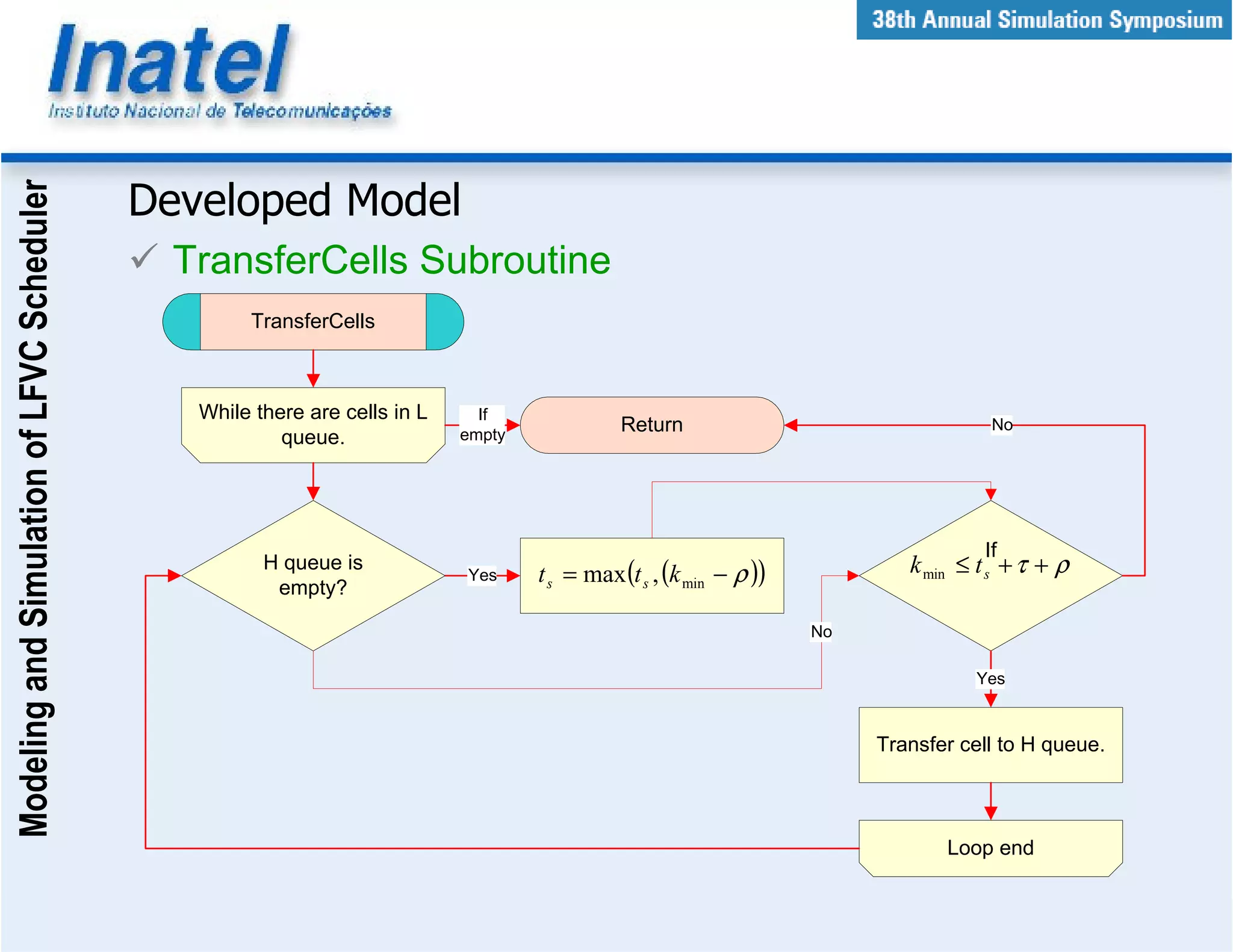
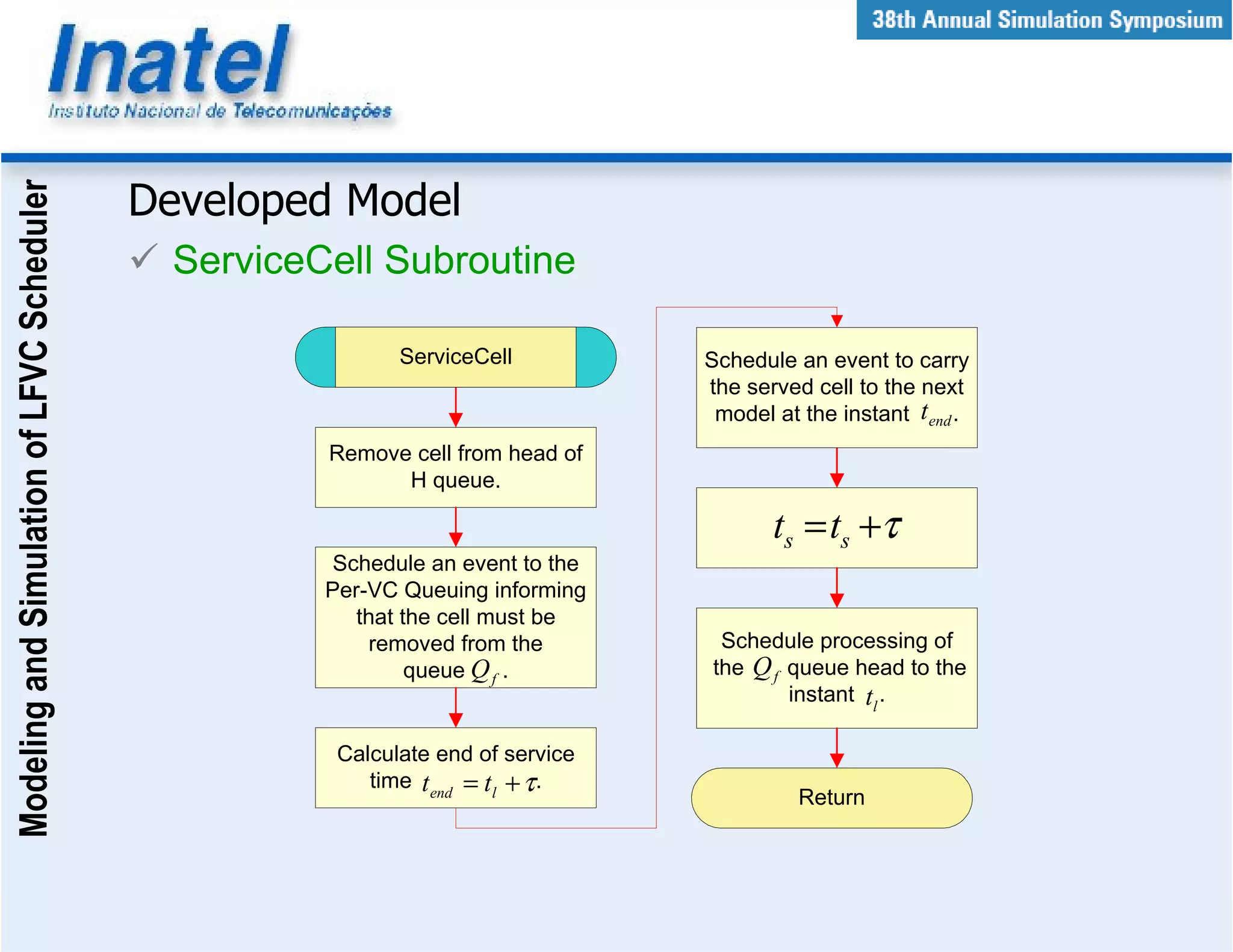
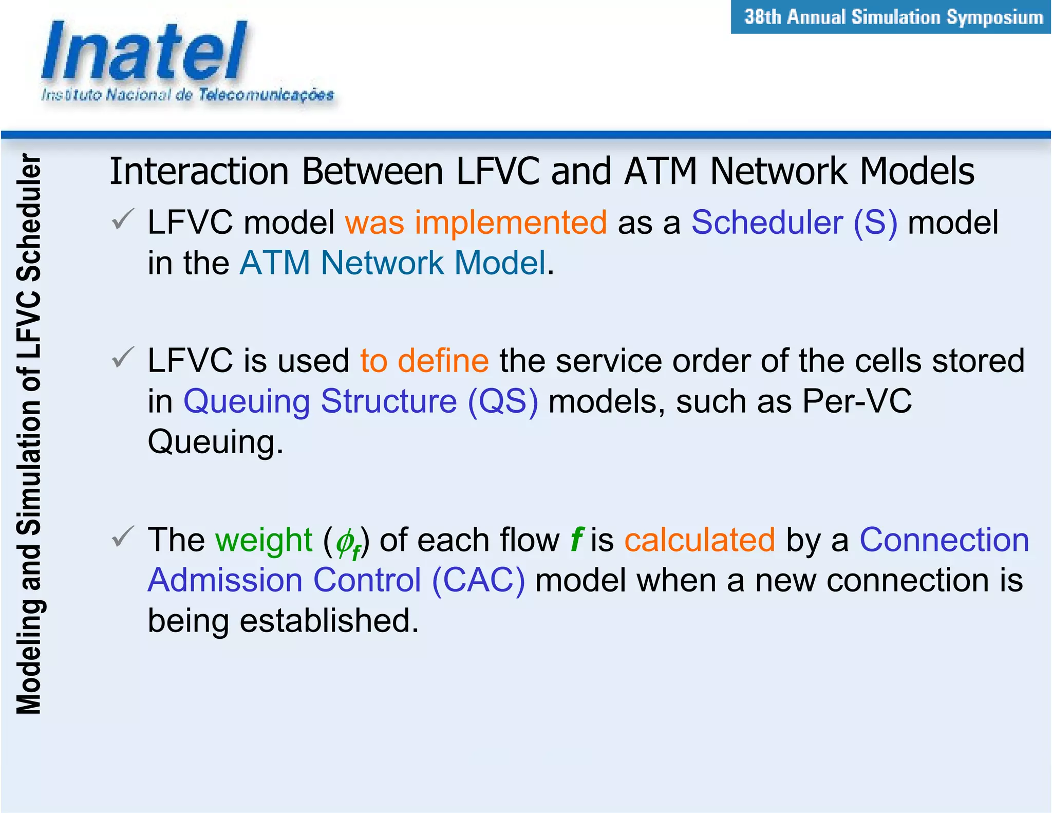
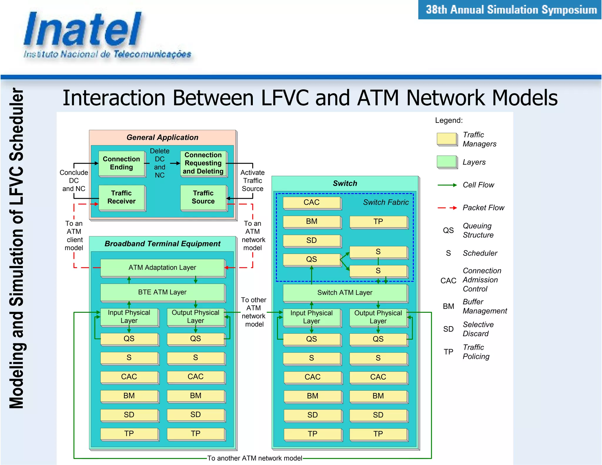
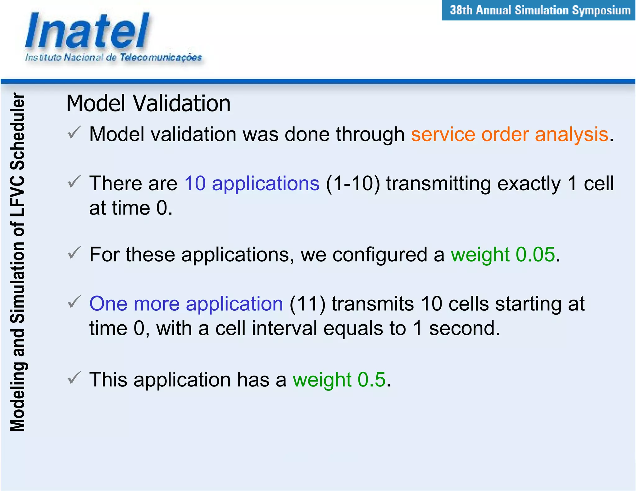
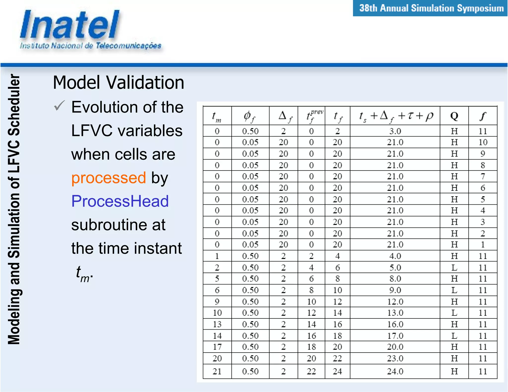
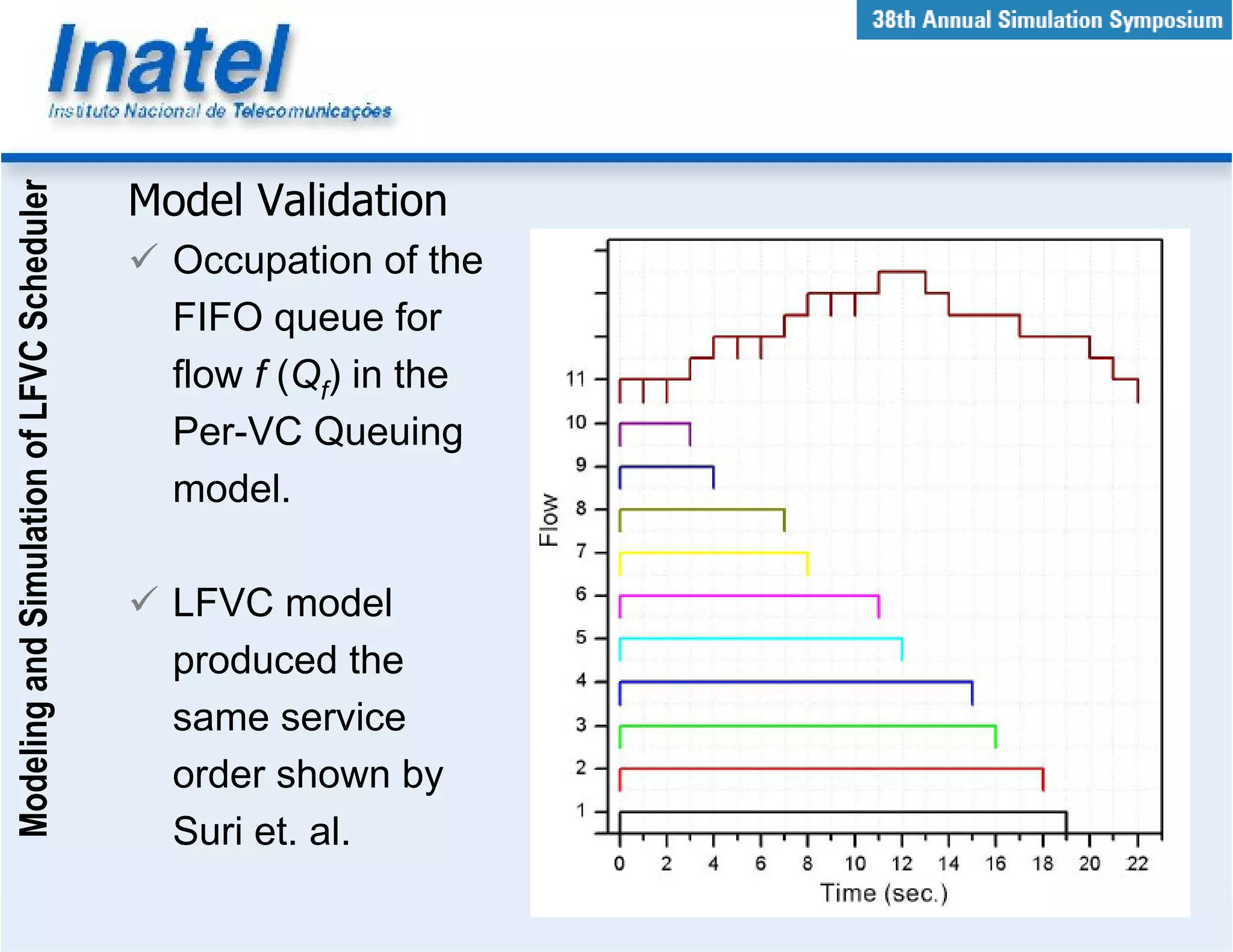
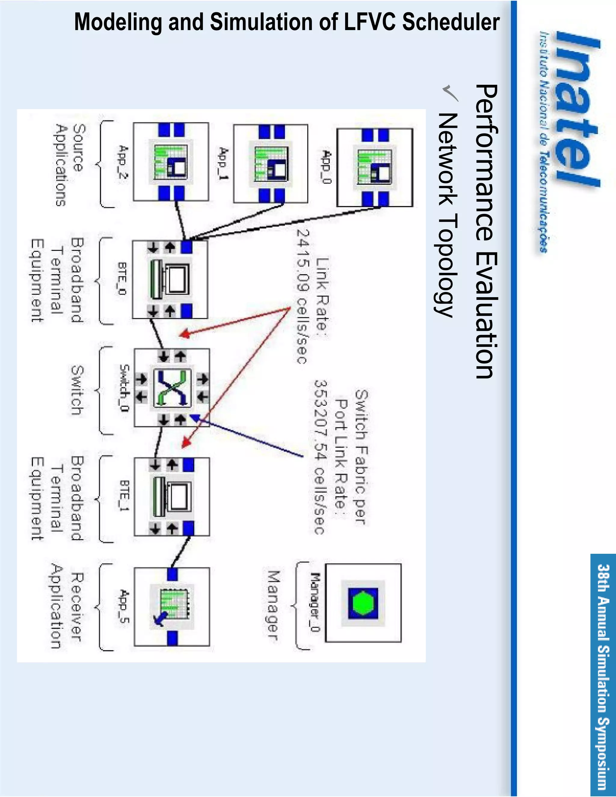
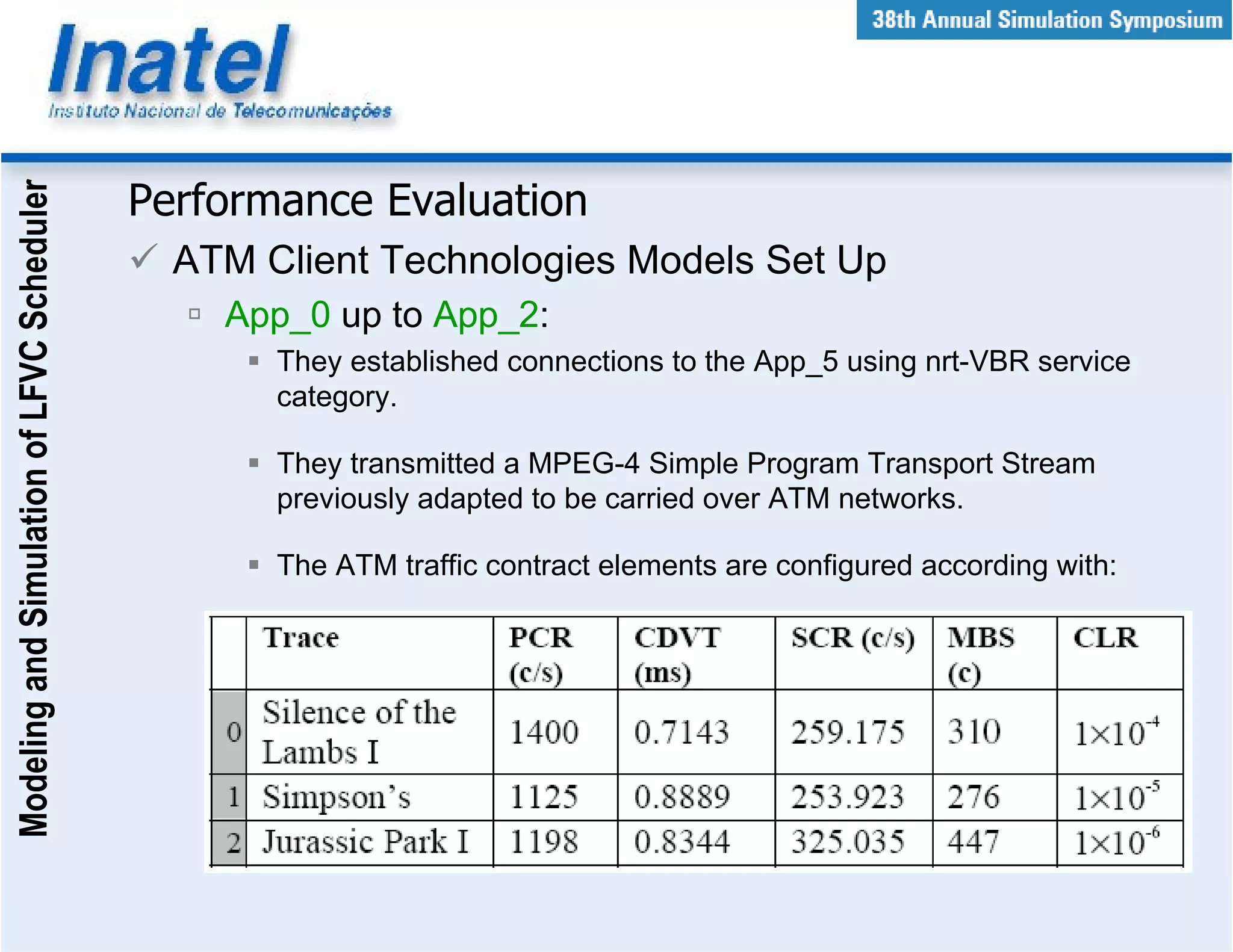
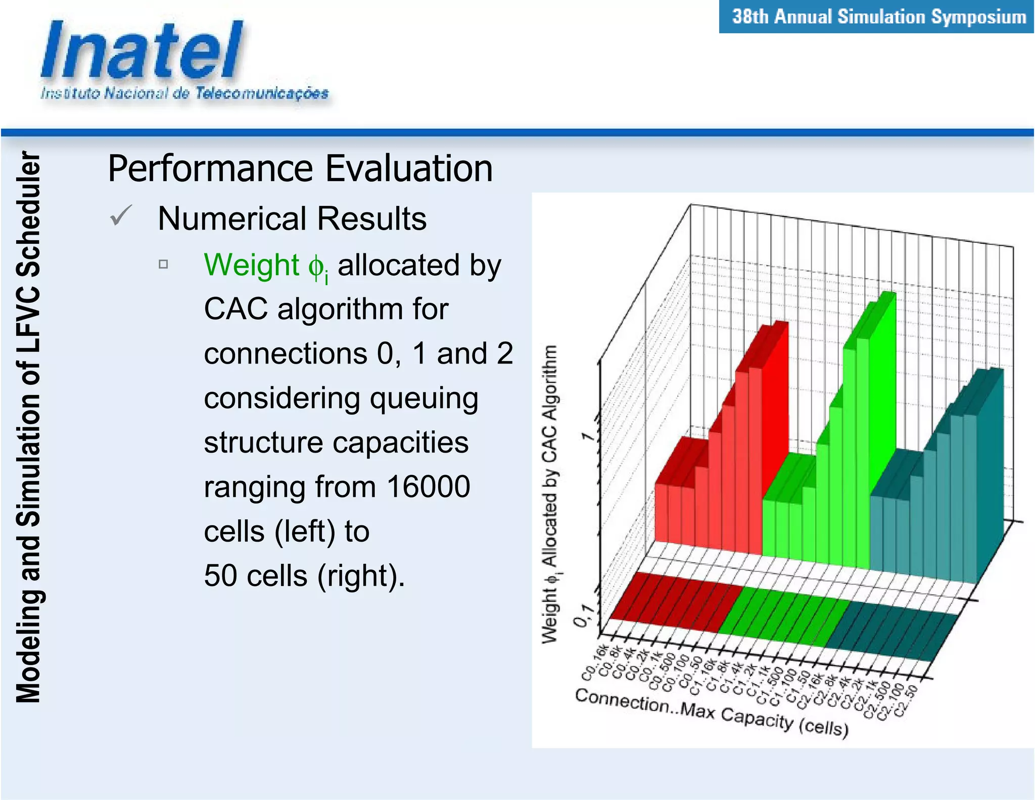
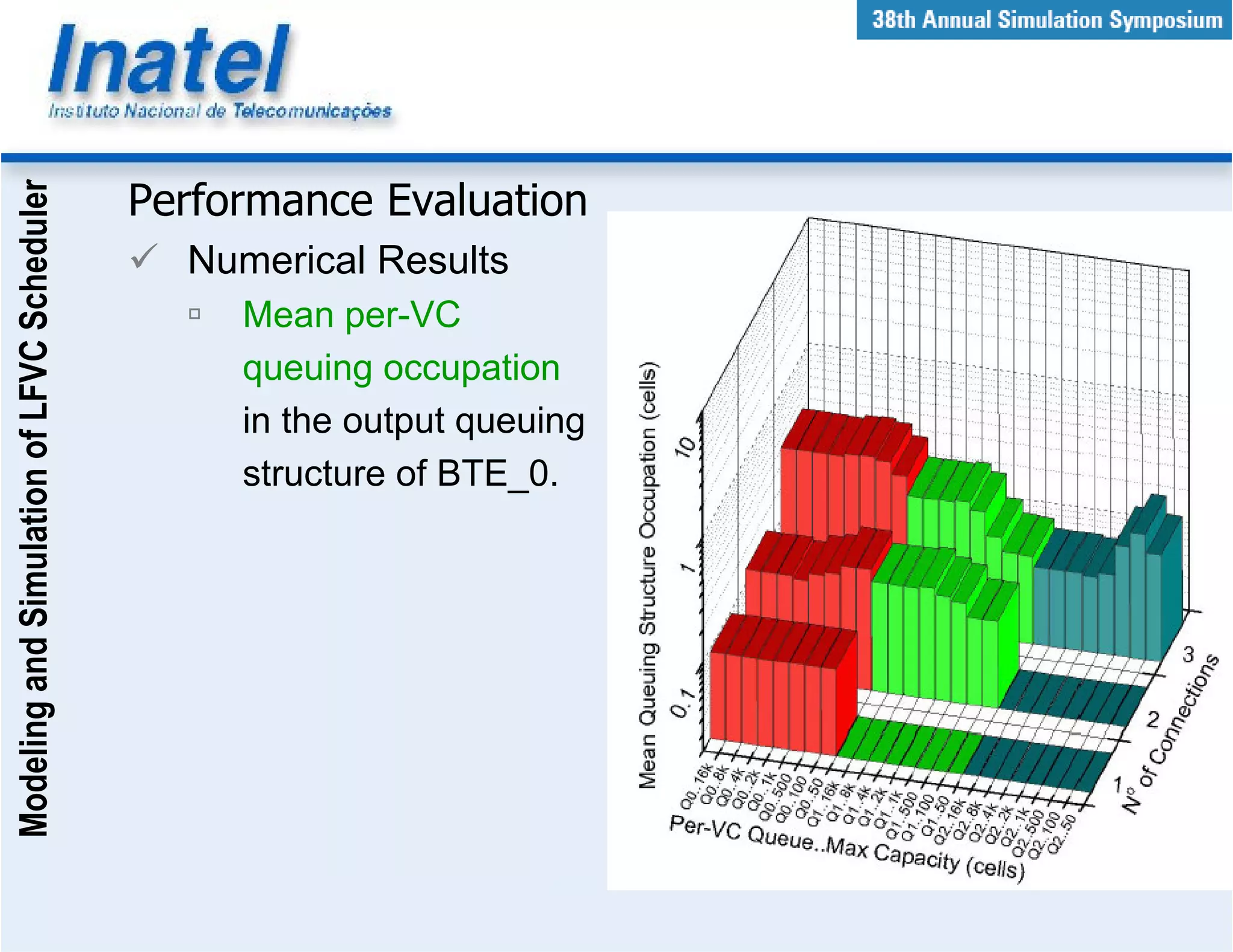
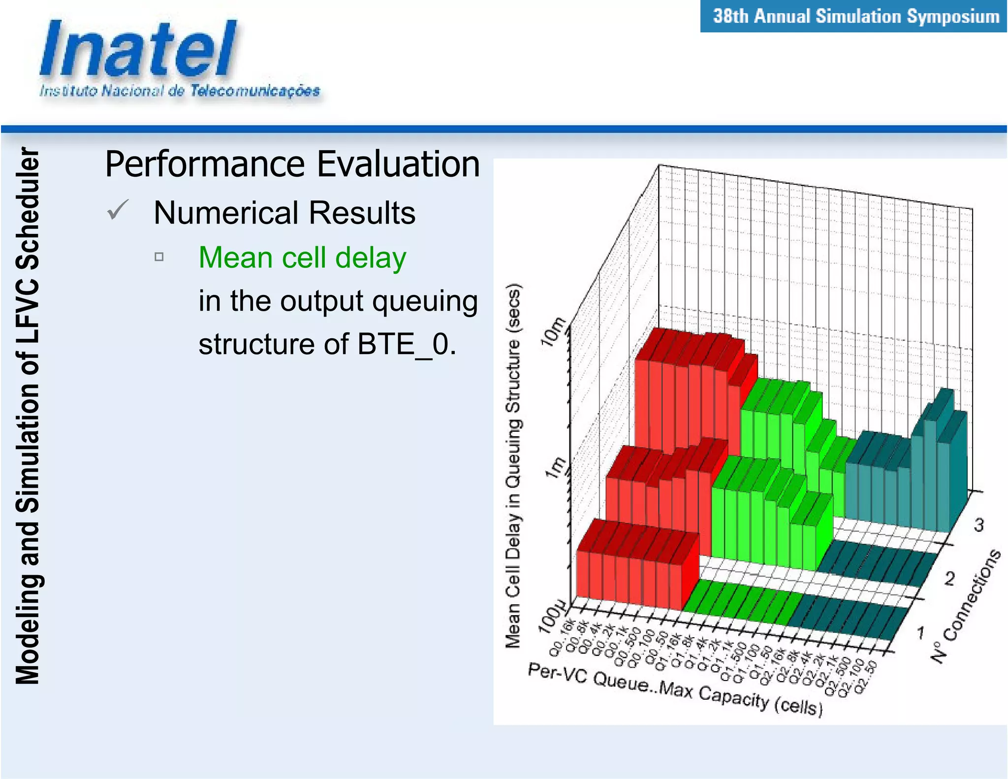
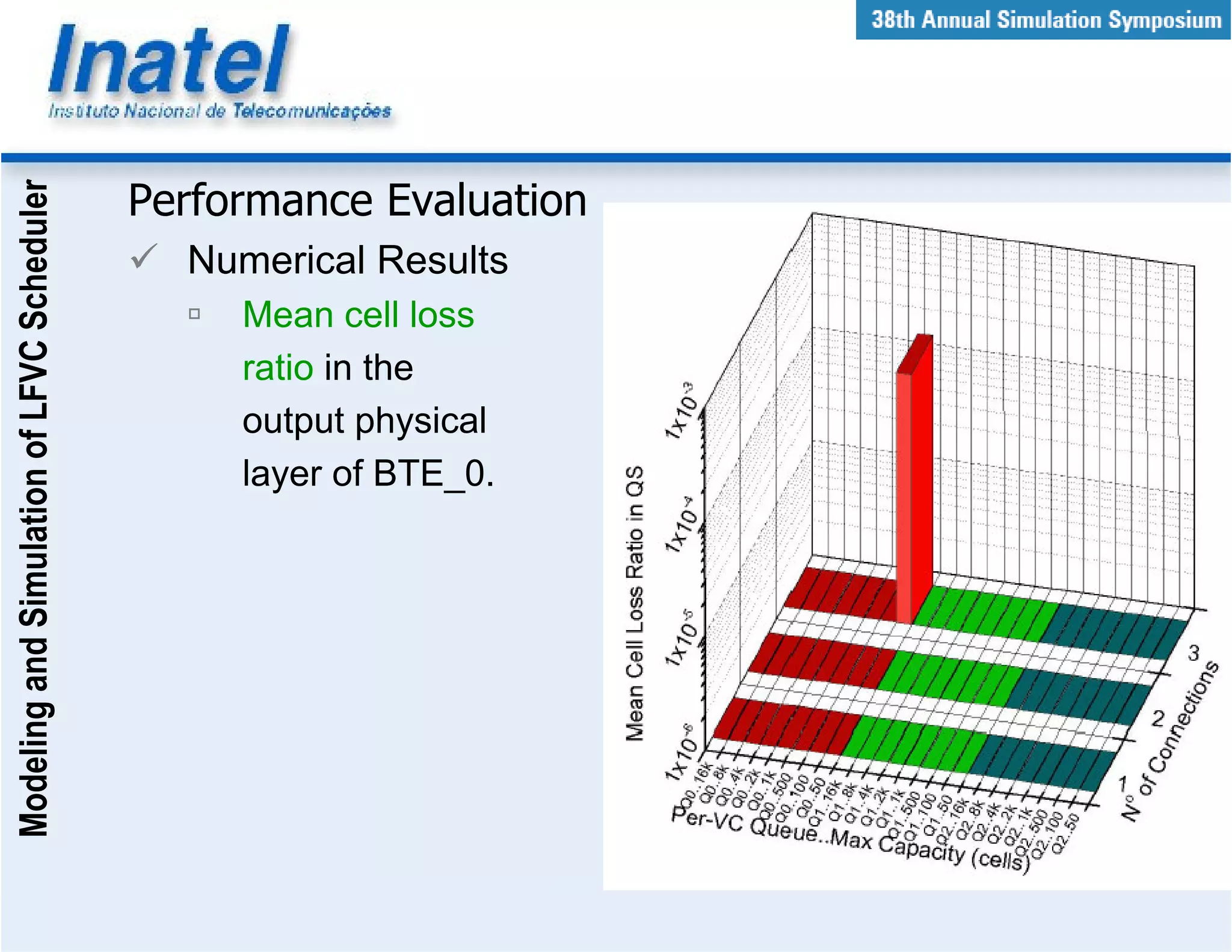


This document describes the modeling and simulation of a Leap Forward Virtual Clock (LFVC) scheduler. It begins with an introduction to scheduling algorithms and why LFVC was chosen. It then explains how the LFVC algorithm works and how it was implemented in a model that interacts with other ATM network models. The model was validated by reproducing expected service order results. Simulations were run to evaluate performance metrics like queue occupation, delay and cell loss for different traffic scenarios and queue sizes. Results demonstrated the model's ability to analyze quality of service in ATM networks and isolate effects between connections.