COMPRESSION MEMBERS
• Compressionmembers are structural elements designed to resist axial compressive forces.
Common tension members are columns, truss members (top chords, struts and webs), bracings for
buildings and bridges.
3.
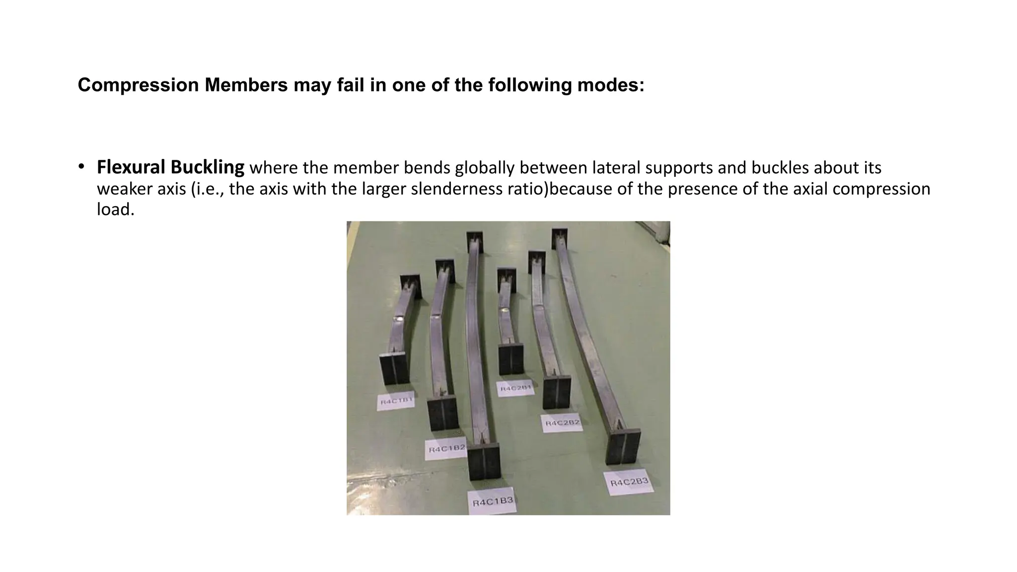
Compression Members mayfail in one of the following modes:
• Flexural Buckling where the member bends globally between lateral supports and buckles about its
weaker axis (i.e., the axis with the larger slenderness ratio)because of the presence of the axial compression
load.
4.
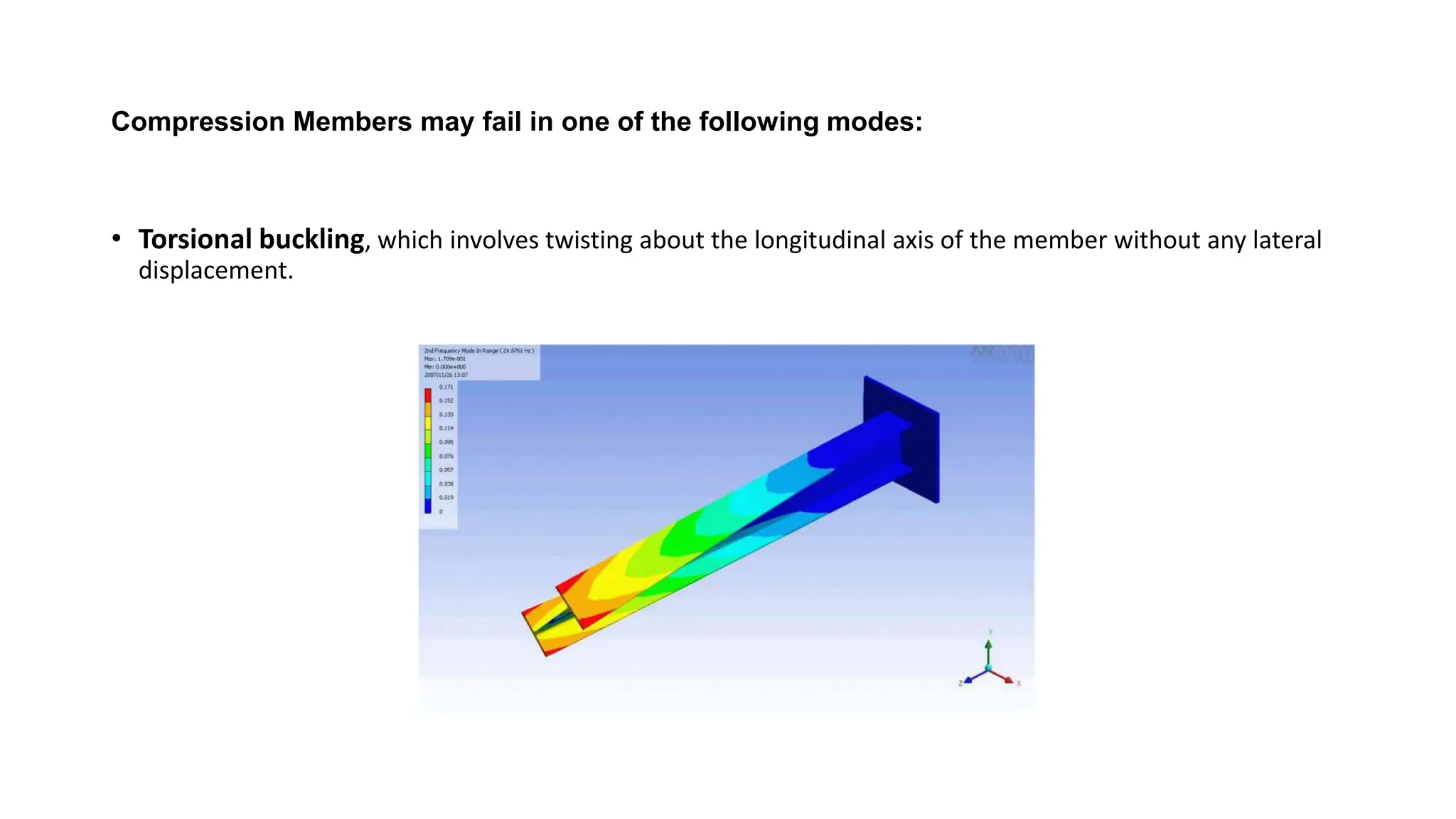
Compression Members mayfail in one of the following modes:
• Torsional buckling, which involves twisting about the longitudinal axis of the member without any lateral
displacement.
5.
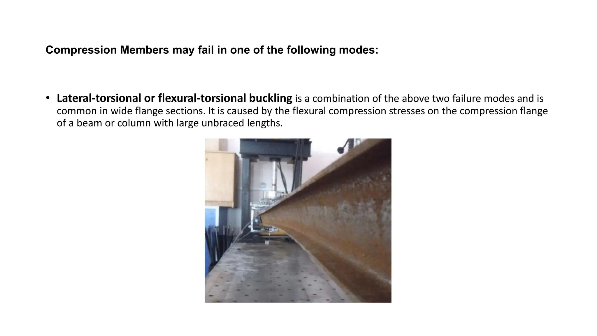
Compression Members mayfail in one of the following modes:
• Lateral-torsional or flexural-torsional buckling is a combination of the above two failure modes and is
common in wide flange sections. It is caused by the flexural compression stresses on the compression flange
of a beam or column with large unbraced lengths.
6.
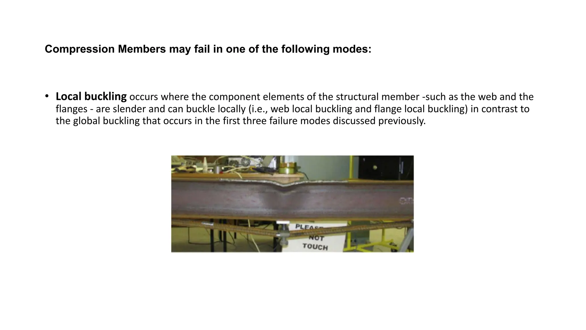
Compression Members mayfail in one of the following modes:
• Local buckling occurs where the component elements of the structural member -such as the web and the
flanges - are slender and can buckle locally (i.e., web local buckling and flange local buckling) in contrast to
the global buckling that occurs in the first three failure modes discussed previously.
7.
COLUMN THEORY
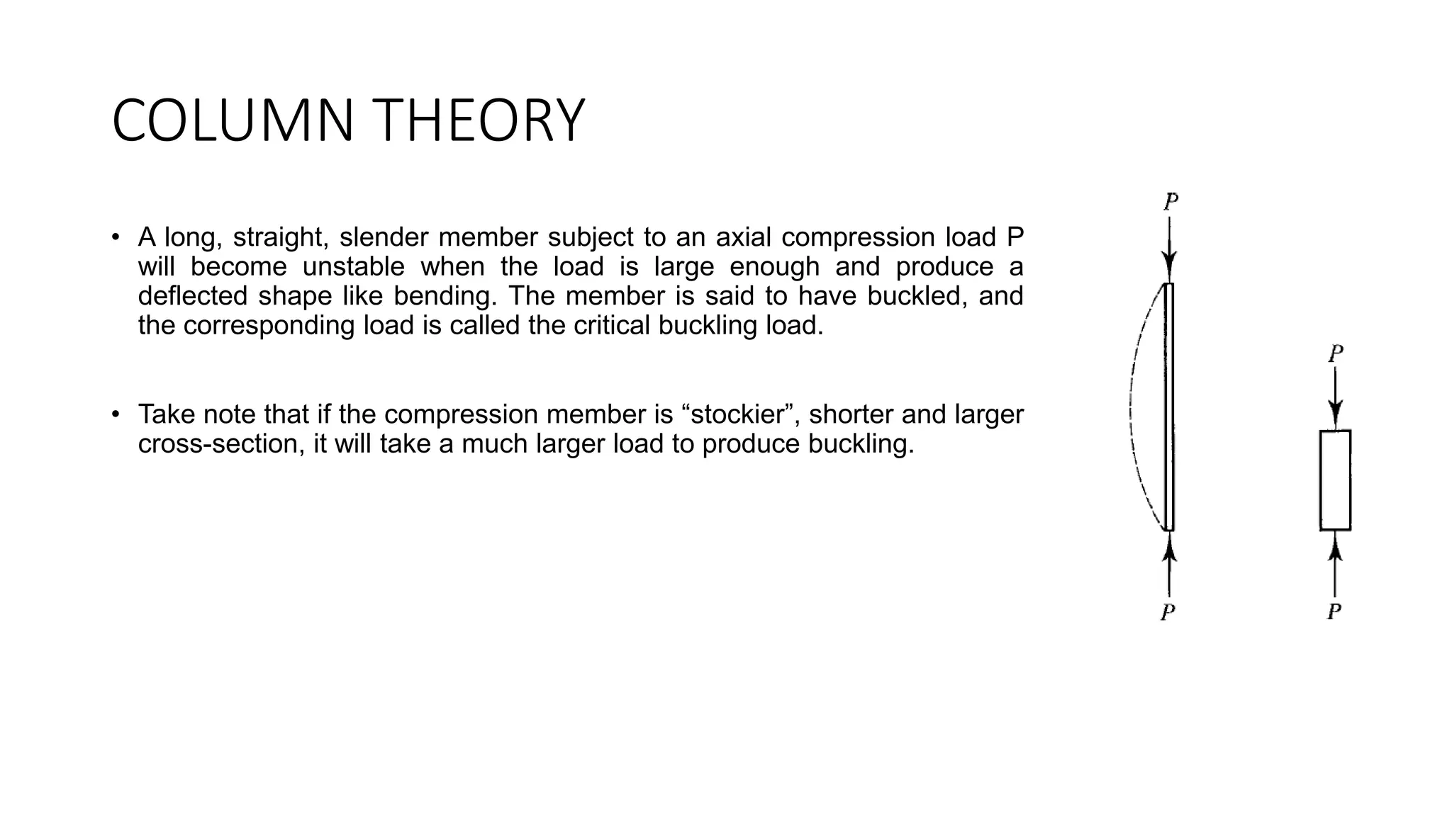
• Along, straight, slender member subject to an axial compression load P
will become unstable when the load is large enough and produce a
deflected shape like bending. The member is said to have buckled, and
the corresponding load is called the critical buckling load.
• Take note that if the compression member is “stockier”, shorter and larger
cross-section, it will take a much larger load to produce buckling.
8.
EULER BUCKLING LOAD
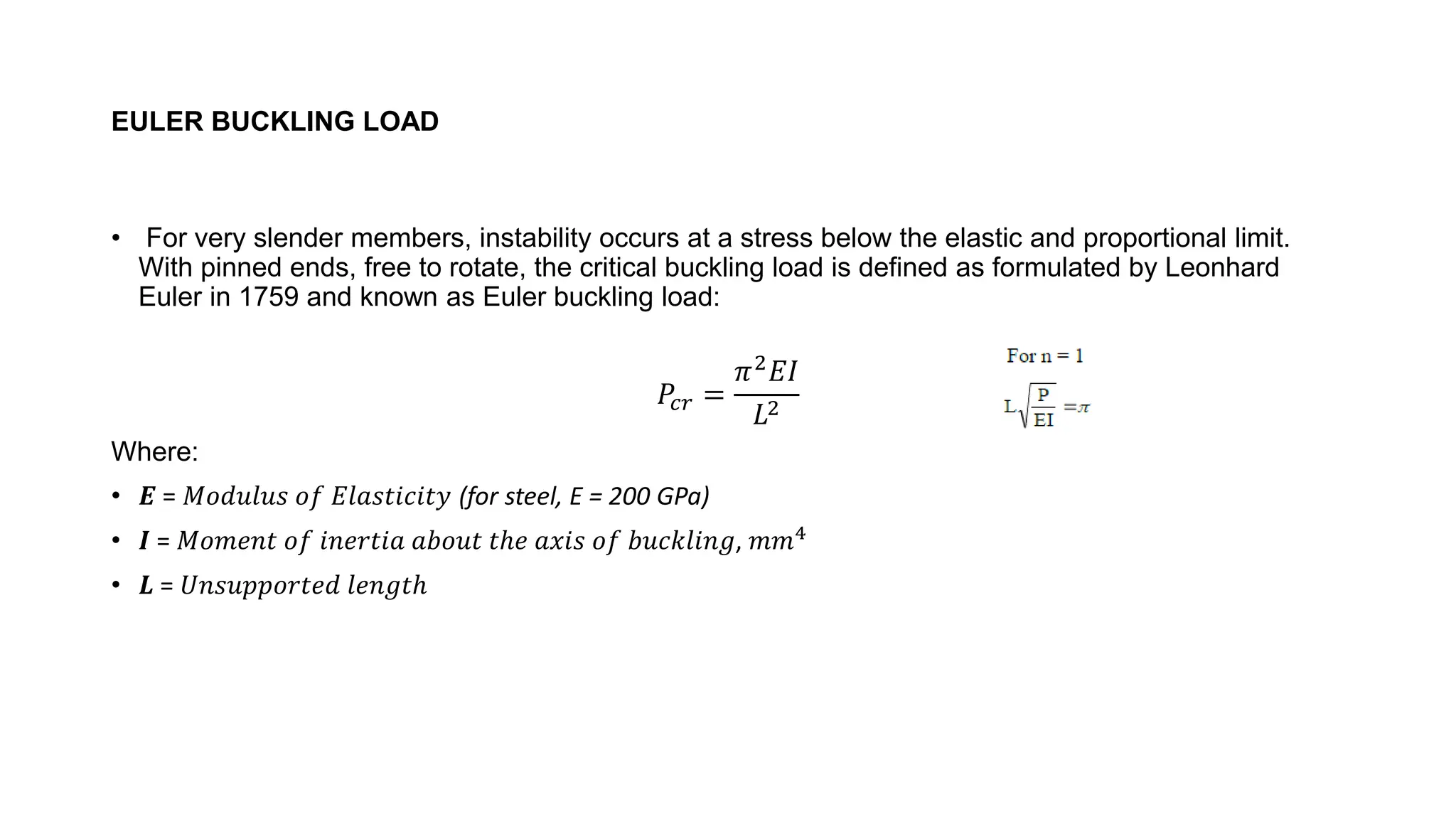
•For very slender members, instability occurs at a stress below the elastic and proportional limit.
With pinned ends, free to rotate, the critical buckling load is defined as formulated by Leonhard
Euler in 1759 and known as Euler buckling load:
𝑃𝑐𝑟 =
𝜋2𝐸𝐼
𝐿2
Where:
• 𝑬 = 𝑀𝑜𝑑𝑢𝑙𝑢𝑠 𝑜𝑓 𝐸𝑙𝑎𝑠𝑡𝑖𝑐𝑖𝑡𝑦 (for steel, E = 200 GPa)
• 𝑰 = 𝑀𝑜𝑚𝑒𝑛𝑡 𝑜𝑓 𝑖𝑛𝑒𝑟𝑡𝑖𝑎 𝑎𝑏𝑜𝑢𝑡 𝑡ℎ𝑒 𝑎𝑥𝑖𝑠 𝑜𝑓 𝑏𝑢𝑐𝑘𝑙𝑖𝑛𝑔, 𝑚𝑚4
• 𝑳 = 𝑈𝑛𝑠𝑢𝑝𝑝𝑜𝑟𝑡𝑒𝑑 𝑙𝑒𝑛𝑔𝑡ℎ
9.
EULER BUCKLING LOAD
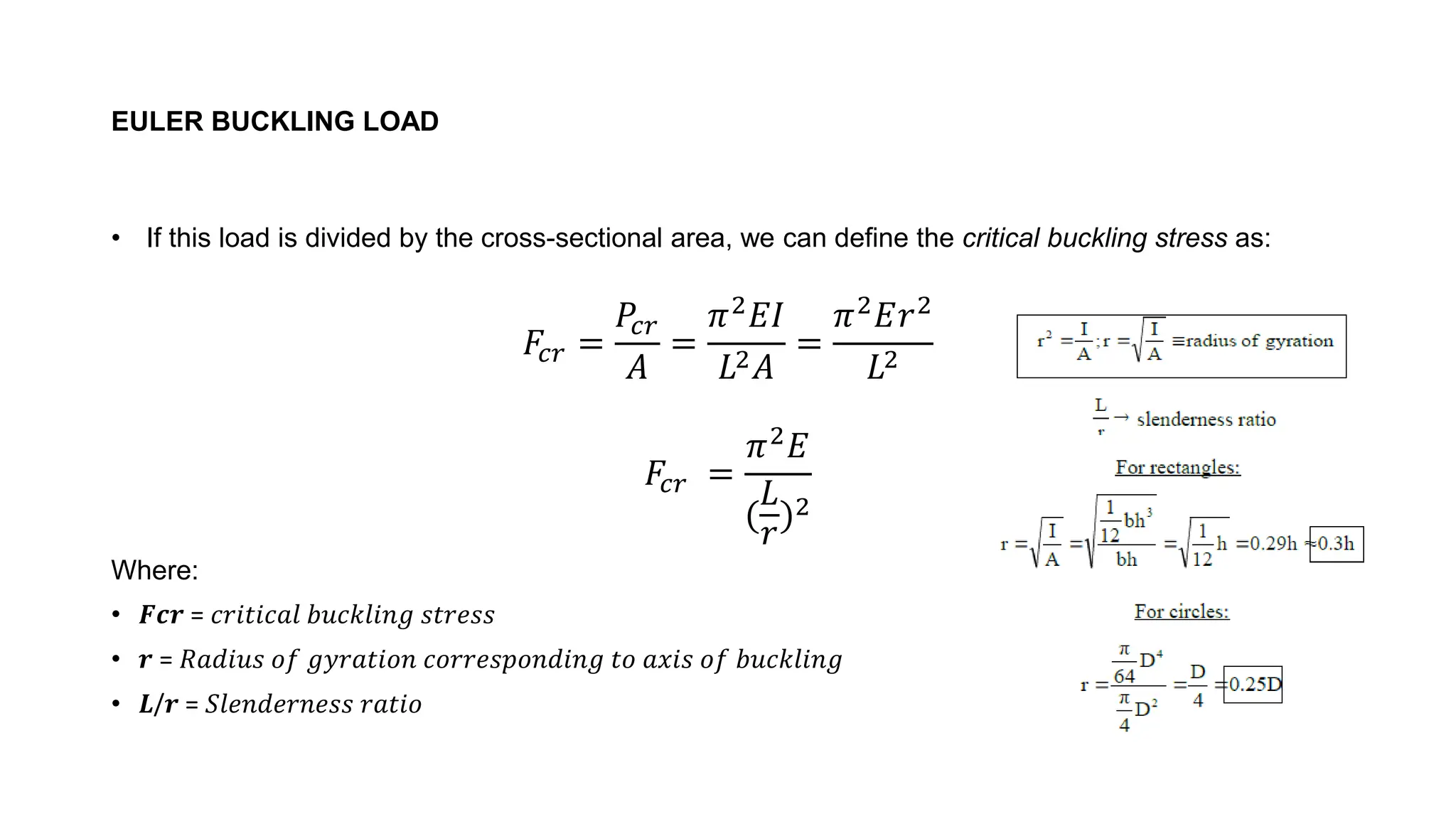
•If this load is divided by the cross-sectional area, we can define the critical buckling stress as:
𝐹𝑐𝑟 =
𝑃𝑐𝑟
𝐴
=
𝜋2
𝐸𝐼
𝐿2𝐴
=
𝜋2
𝐸𝑟2
𝐿2
𝐹𝑐𝑟 =
𝜋2𝐸
(
𝐿
𝑟
)2
Where:
• 𝑭𝒄𝒓 = 𝑐𝑟𝑖𝑡𝑖𝑐𝑎𝑙 𝑏𝑢𝑐𝑘𝑙𝑖𝑛𝑔 𝑠𝑡𝑟𝑒𝑠𝑠
• 𝒓 = 𝑅𝑎𝑑𝑖𝑢𝑠 𝑜𝑓 𝑔𝑦𝑟𝑎𝑡𝑖𝑜𝑛 𝑐𝑜𝑟𝑟𝑒𝑠𝑝𝑜𝑛𝑑𝑖𝑛𝑔 𝑡𝑜 𝑎𝑥𝑖𝑠 𝑜𝑓 𝑏𝑢𝑐𝑘𝑙𝑖𝑛𝑔
• 𝑳/𝒓 = 𝑆𝑙𝑒𝑛𝑑𝑒𝑟𝑛𝑒𝑠𝑠 𝑟𝑎𝑡𝑖𝑜
10.
CONCEPT OF BUCKLING
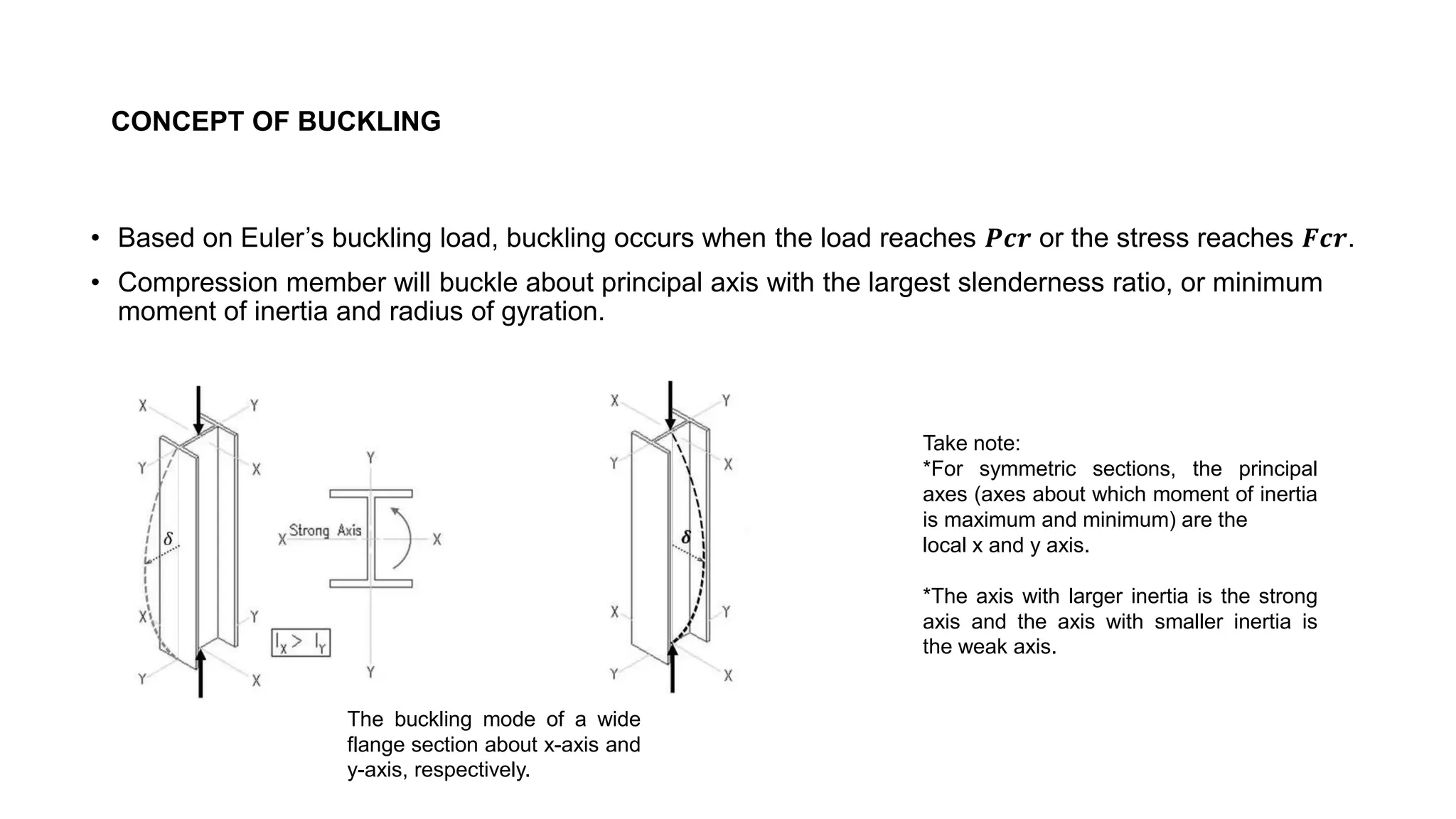
•Based on Euler’s buckling load, buckling occurs when the load reaches 𝑷𝒄𝒓 or the stress reaches 𝑭𝒄𝒓.
• Compression member will buckle about principal axis with the largest slenderness ratio, or minimum
moment of inertia and radius of gyration.
The buckling mode of a wide
flange section about x-axis and
y-axis, respectively.
Take note:
*For symmetric sections, the principal
axes (axes about which moment of inertia
is maximum and minimum) are the
local x and y axis.
*The axis with larger inertia is the strong
axis and the axis with smaller inertia is
the weak axis.
12.
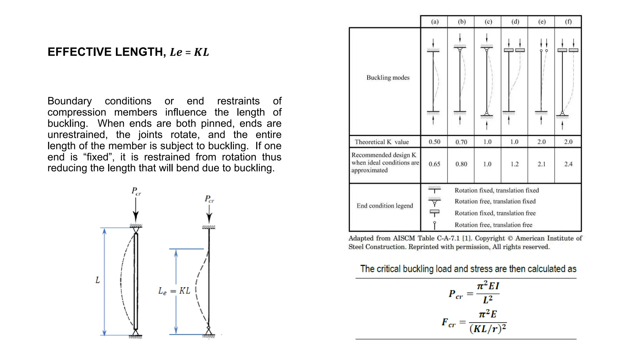
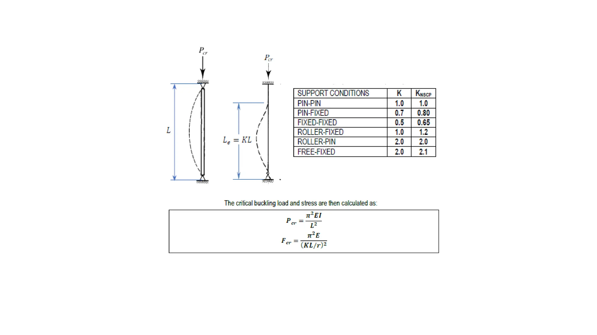
EFFECTIVE LENGTH, 𝑳𝒆= 𝑲𝑳
Boundary conditions or end restraints of
compression members influence the length of
buckling. When ends are both pinned, ends are
unrestrained, the joints rotate, and the entire
length of the member is subject to buckling. If one
end is “fixed”, it is restrained from rotation thus
reducing the length that will bend due to buckling.
14.
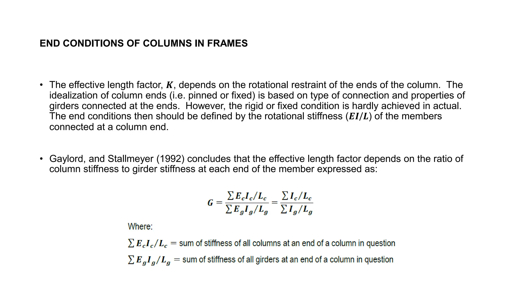
END CONDITIONS OFCOLUMNS IN FRAMES
• The effective length factor, 𝑲, depends on the rotational restraint of the ends of the column. The
idealization of column ends (i.e. pinned or fixed) is based on type of connection and properties of
girders connected at the ends. However, the rigid or fixed condition is hardly achieved in actual.
The end conditions then should be defined by the rotational stiffness (𝑬𝑰/𝑳) of the members
connected at a column end.
• Gaylord, and Stallmeyer (1992) concludes that the effective length factor depends on the ratio of
column stiffness to girder stiffness at each end of the member expressed as:
16.
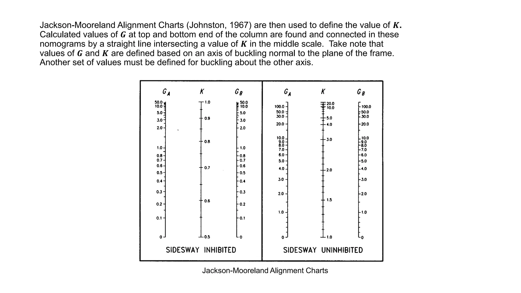
Jackson-Mooreland Alignment Charts(Johnston, 1967) are then used to define the value of 𝑲.
Calculated values of 𝑮 at top and bottom end of the column are found and connected in these
nomograms by a straight line intersecting a value of 𝑲 in the middle scale. Take note that
values of 𝑮 and 𝑲 are defined based on an axis of buckling normal to the plane of the frame.
Another set of values must be defined for buckling about the other axis.
Jackson-Mooreland Alignment Charts
17.
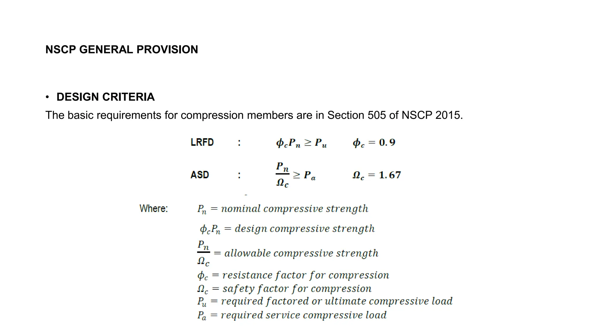
NSCP GENERAL PROVISION
•DESIGN CRITERIA
The basic requirements for compression members are in Section 505 of NSCP 2015.
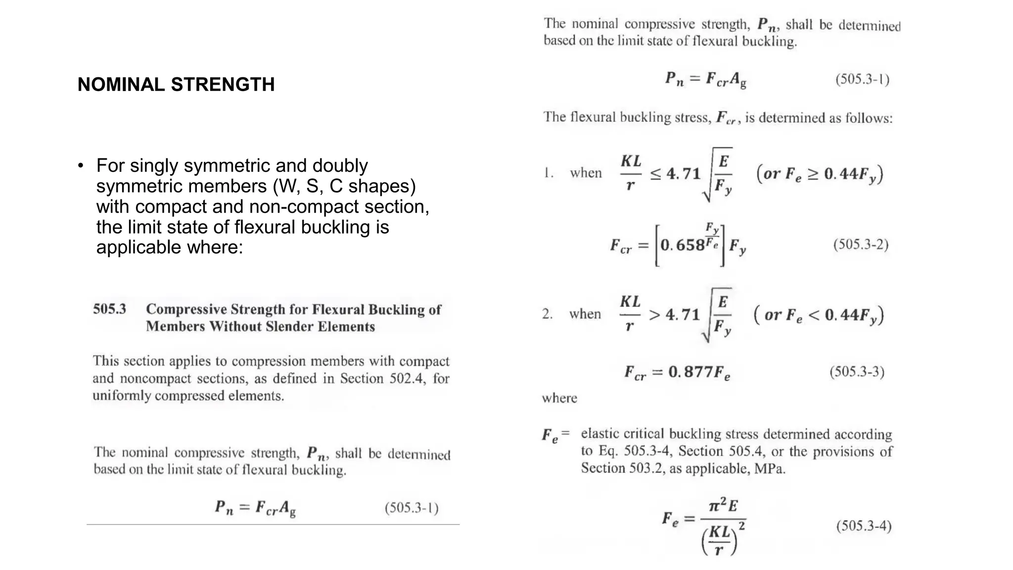
NOMINAL STRENGTH
• Forsingly symmetric and doubly
symmetric members (W, S, C shapes)
with compact and non-compact section,
the limit state of flexural buckling is
applicable where:
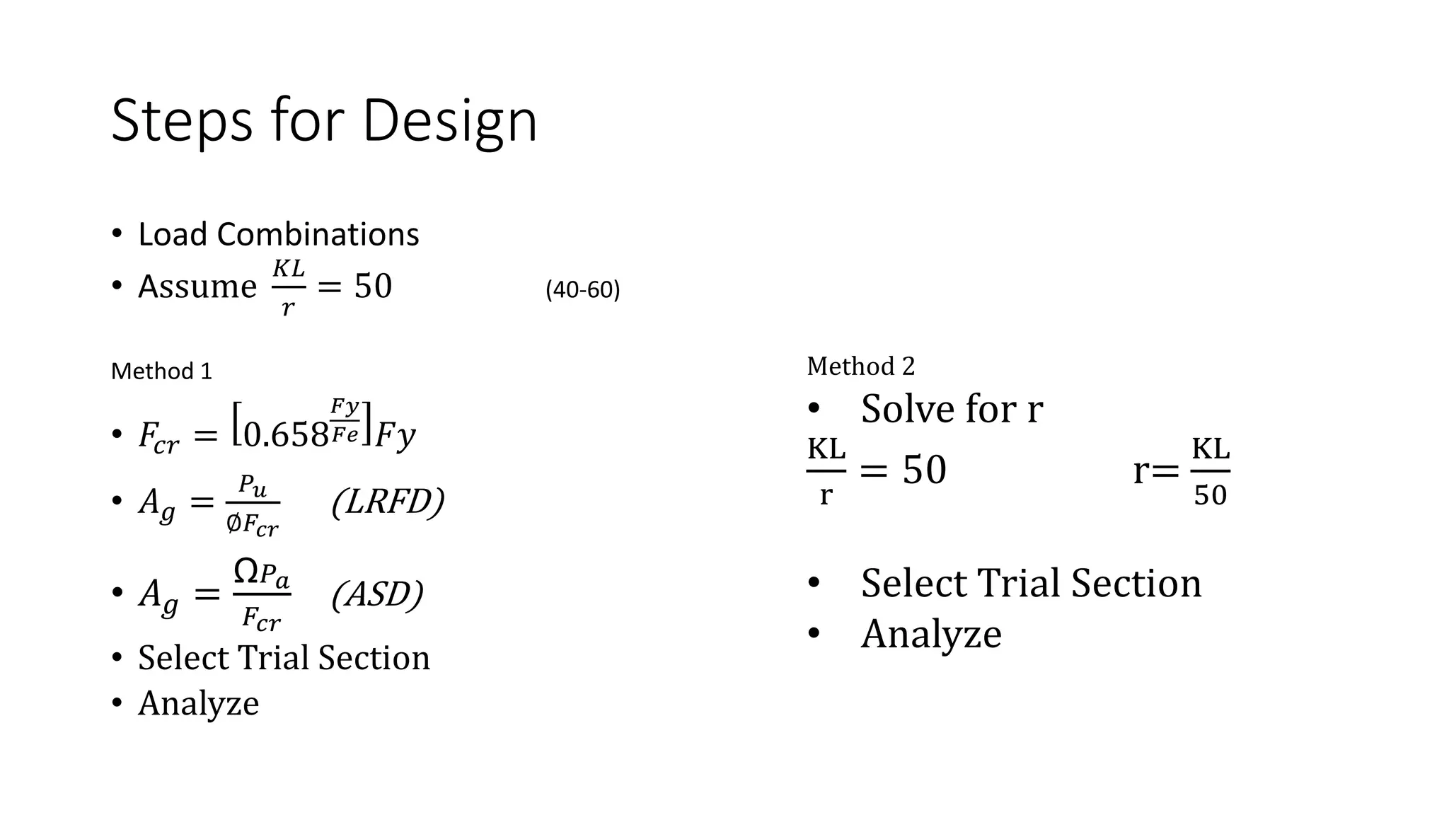
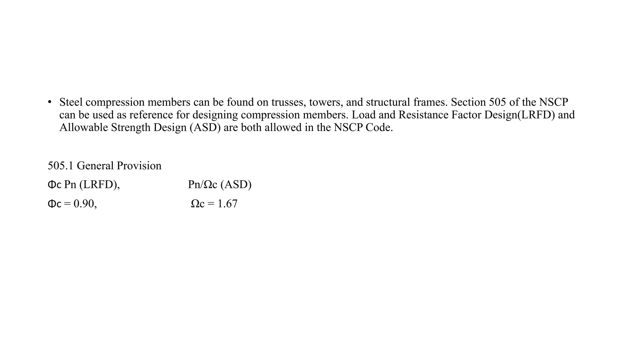
• Steel compressionmembers can be found on trusses, towers, and structural frames. Section 505 of the NSCP
can be used as reference for designing compression members. Load and Resistance Factor Design(LRFD) and
Allowable Strength Design (ASD) are both allowed in the NSCP Code.
505.1 General Provision
Φc Pn (LRFD), Pn/Ωc (ASD)
Φc = 0.90, Ωc = 1.67
23.
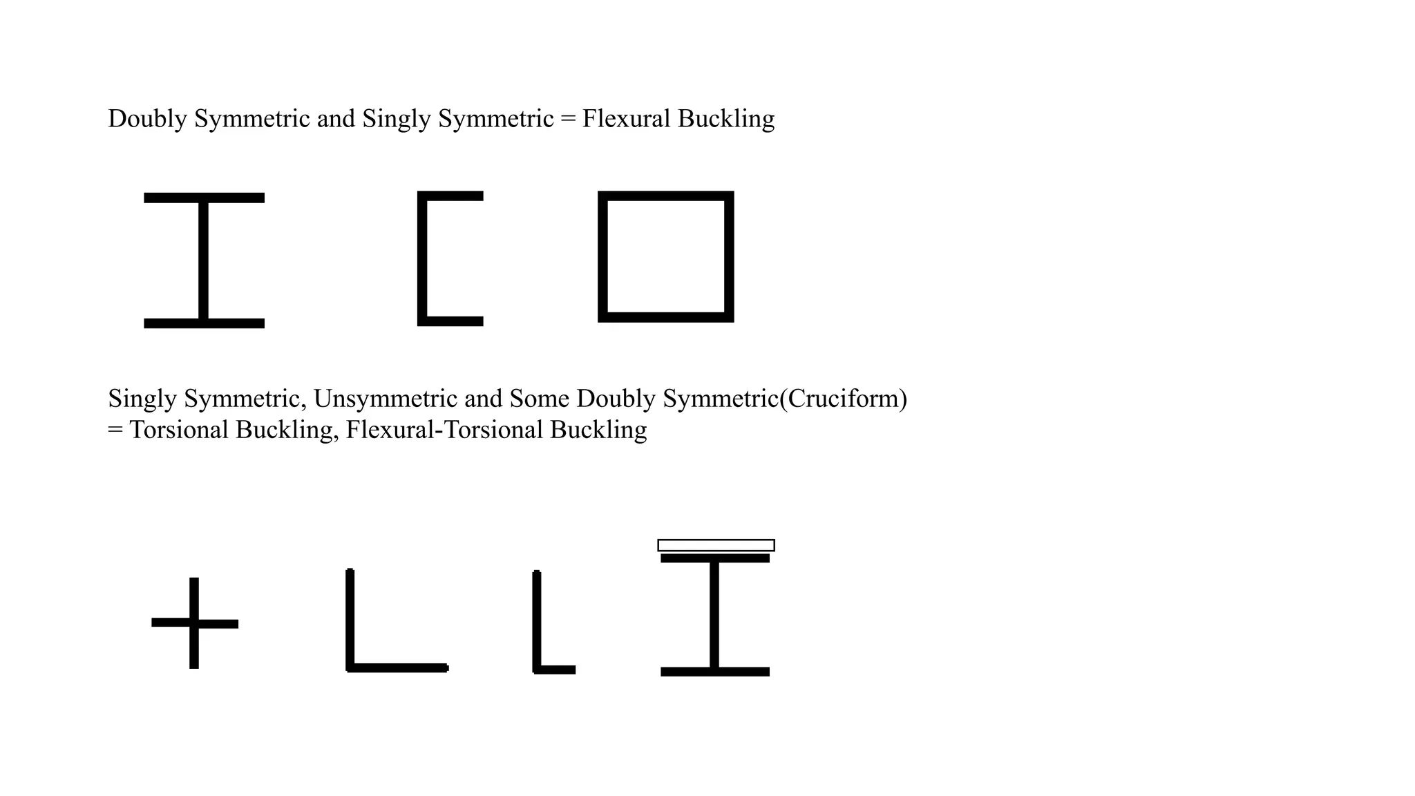
Doubly Symmetric andSingly Symmetric = Flexural Buckling
Singly Symmetric, Unsymmetric and Some Doubly Symmetric(Cruciform)
= Torsional Buckling, Flexural-Torsional Buckling
24.
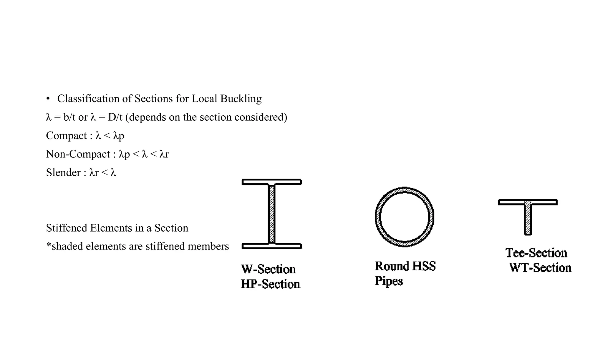
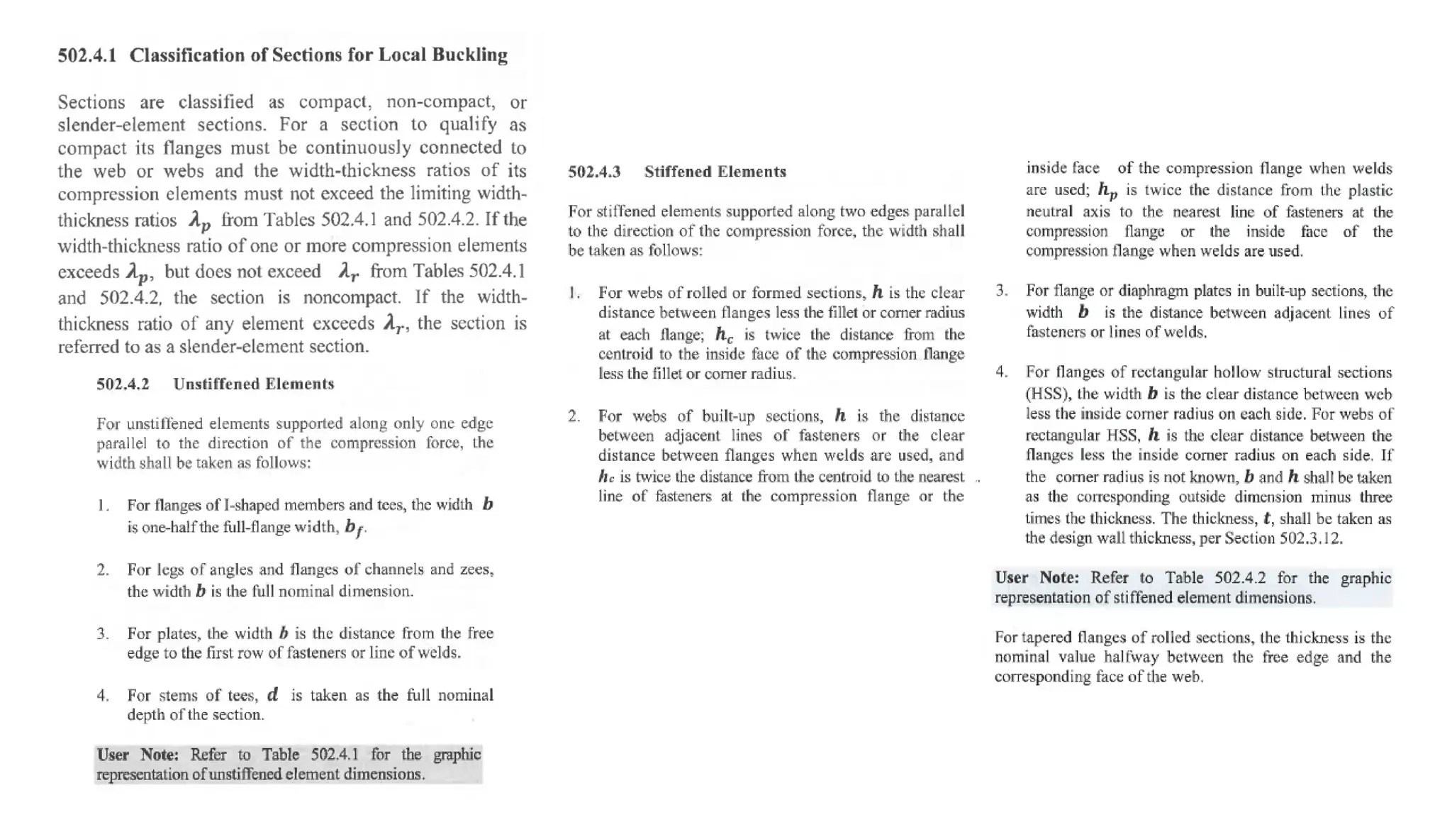
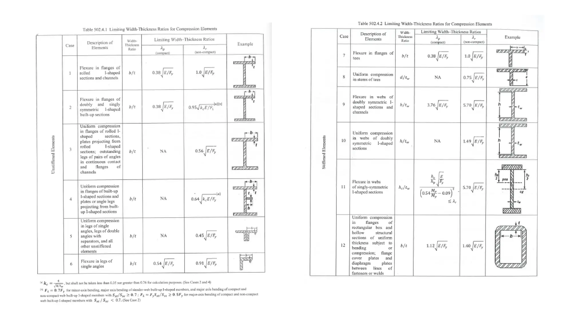
• Classification ofSections for Local Buckling
λ = b/t or λ = D/t (depends on the section considered)
Compact : λ < λp
Non-Compact : λp < λ < λr
Slender : λr < λ
Stiffened Elements in a Section
*shaded elements are stiffened members
27.
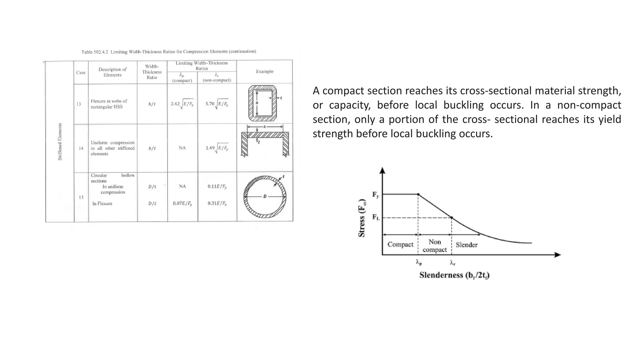
A compact sectionreaches its cross-sectional material strength,
or capacity, before local buckling occurs. In a non-compact
section, only a portion of the cross- sectional reaches its yield
strength before local buckling occurs.
28.
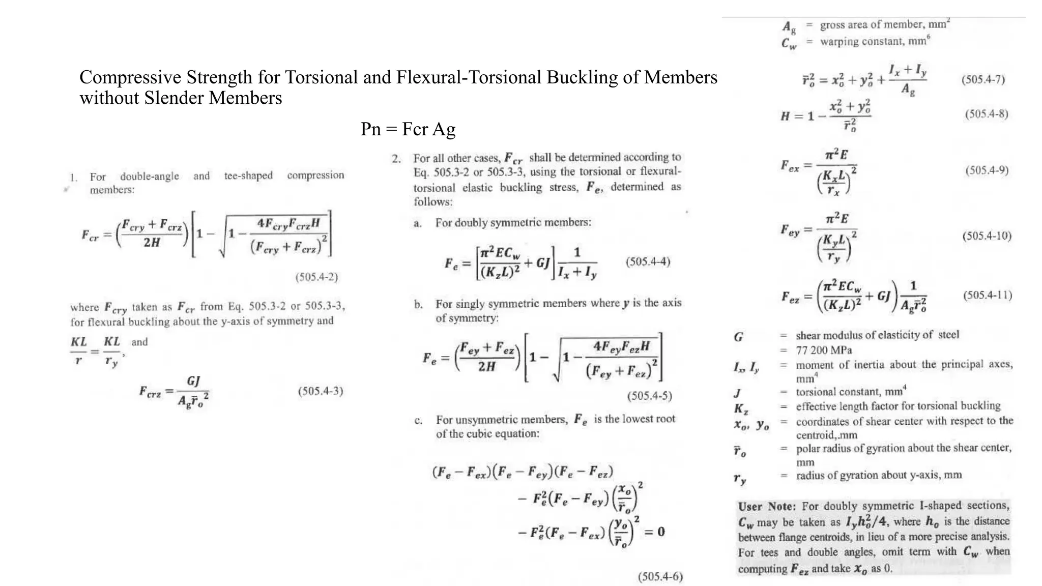
Compressive Strength forTorsional and Flexural-Torsional Buckling of Members
without Slender Members
Pn = Fcr Ag
30.
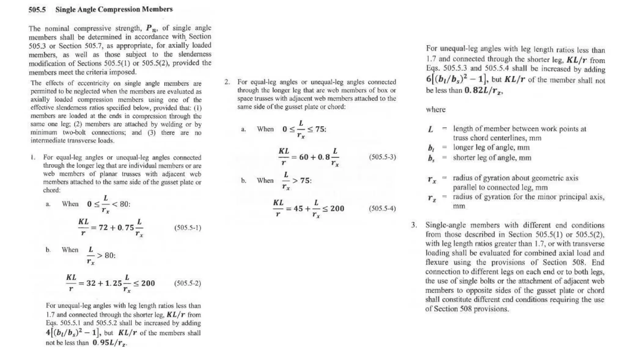
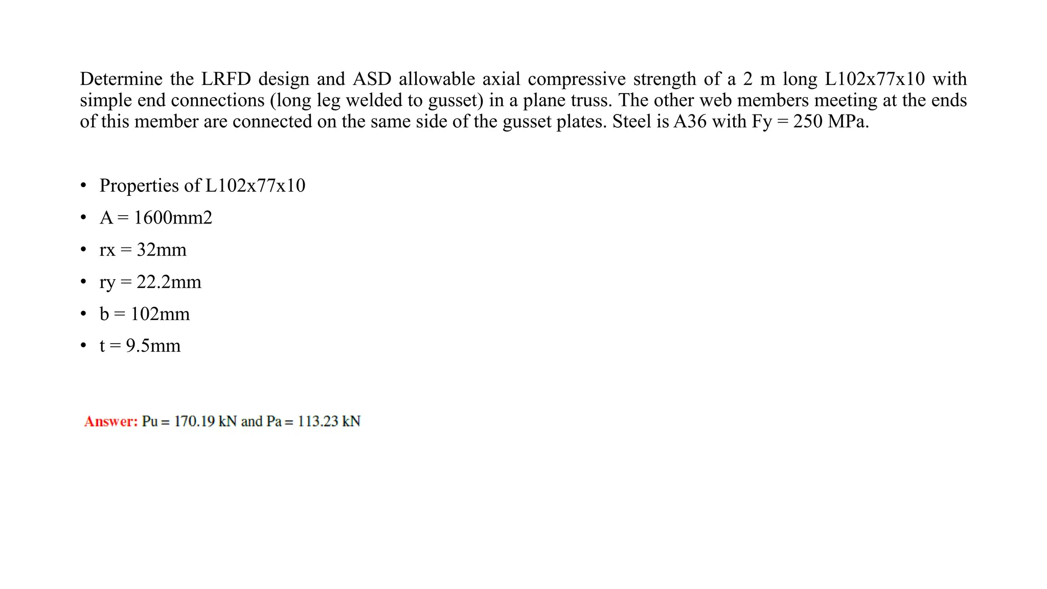
Determine the LRFDdesign and ASD allowable axial compressive strength of a 2 m long L102x77x10 with
simple end connections (long leg welded to gusset) in a plane truss. The other web members meeting at the ends
of this member are connected on the same side of the gusset plates. Steel is A36 with Fy = 250 MPa.
• Properties of L102x77x10
• A = 1600mm2
• rx = 32mm
• ry = 22.2mm
• b = 102mm
• t = 9.5mm