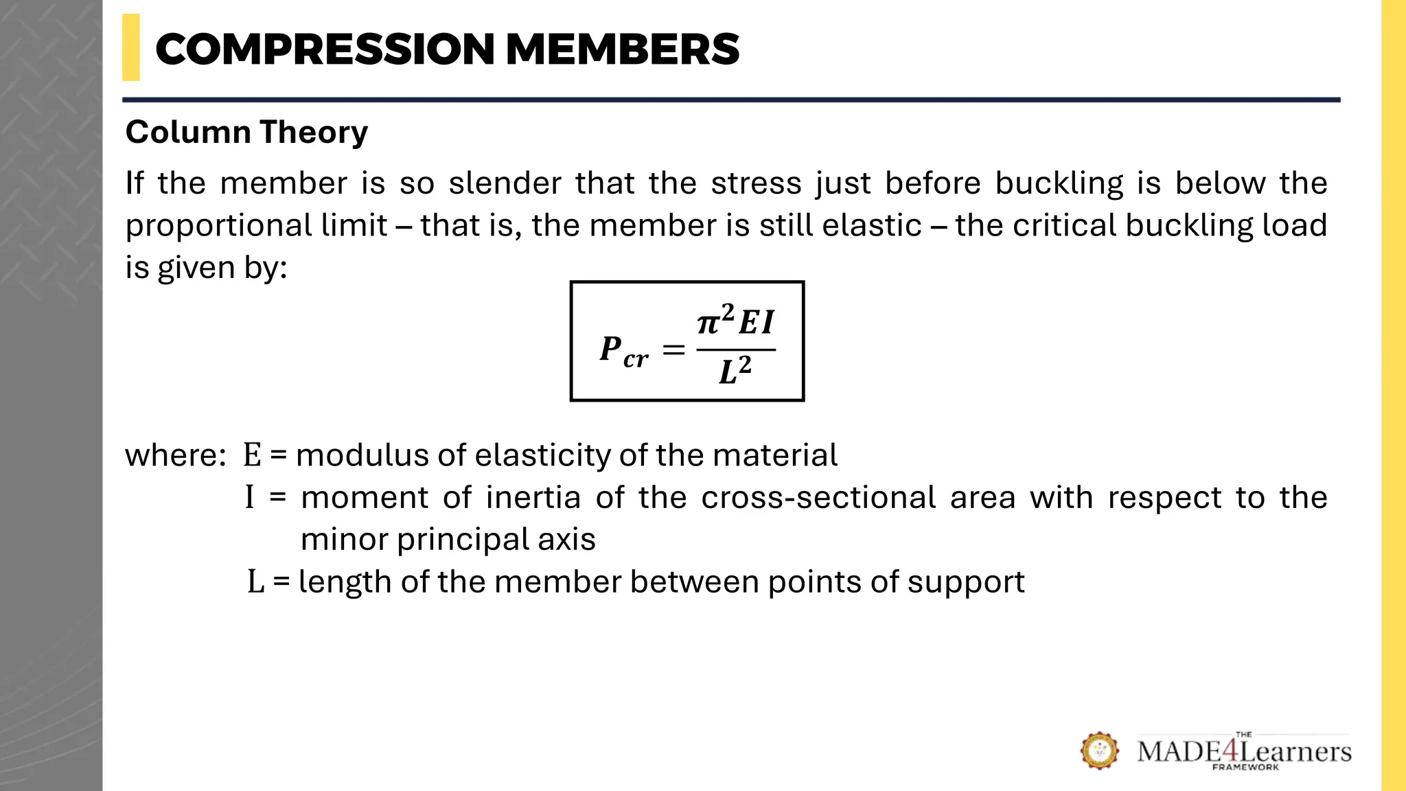
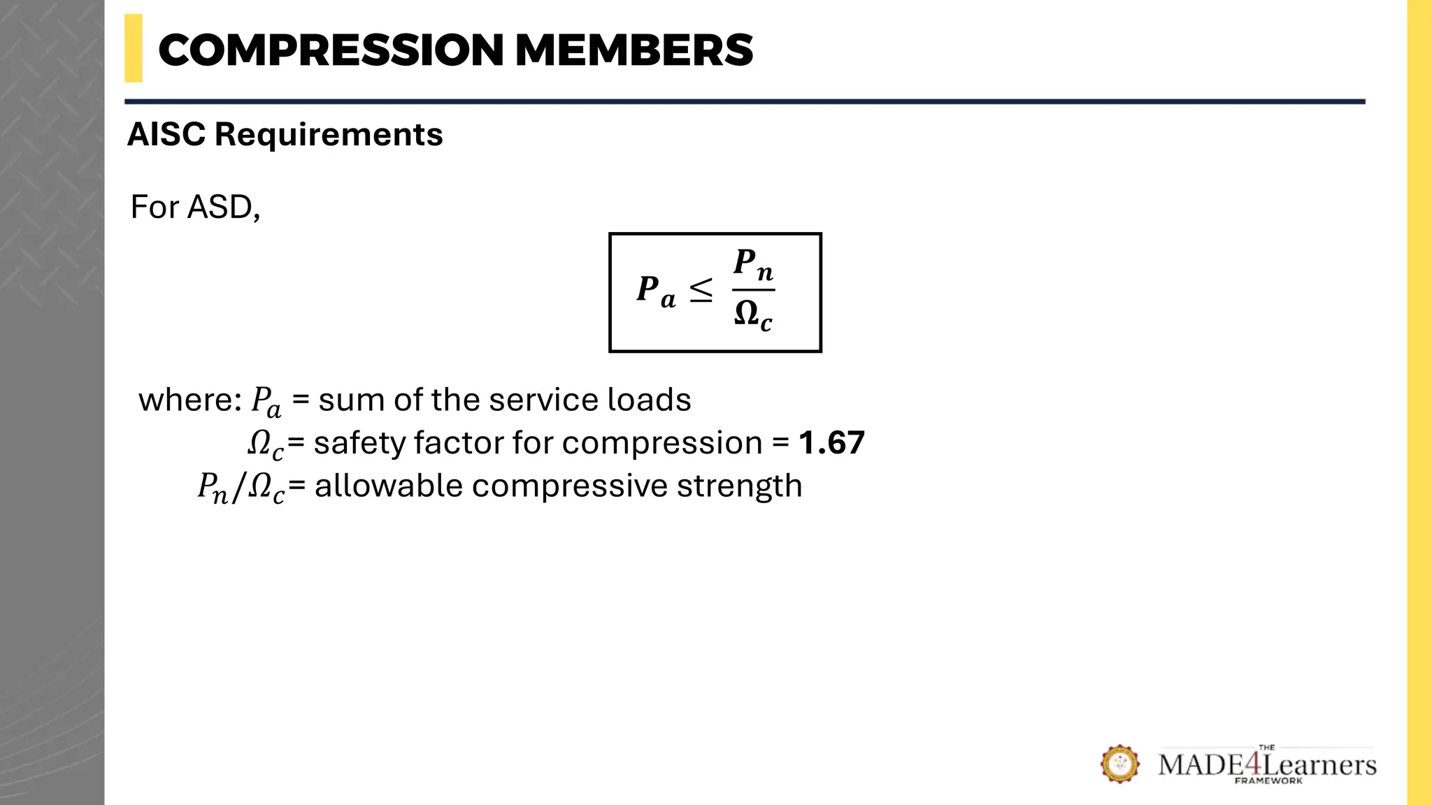
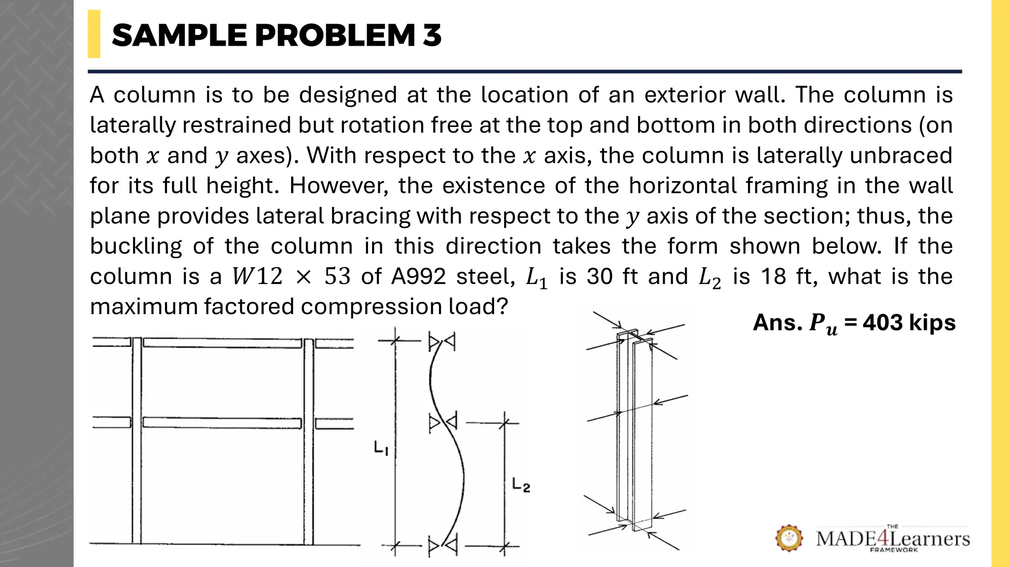
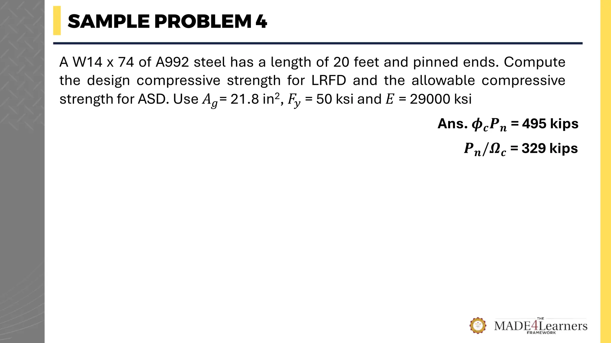
CE497
COMPRESSION MEMBERS
ENGR. DJ LEX YNOT
STEEL AND TIMBER DESIGN
COMPRESSION MEMBERS
Compression members are structural elements that are subjected only to axial
compressive forces (i.e. loads are applied along a longitudinal axis through the
centroid of the member cross section)
This ideal state is never achieved in reality because some eccentricity is
inevitable. Bending will result, but it can usually be regarded as secondary and
can be neglected if the theoretical loading condition is closely approximated
The most common type of compression member occurring in buildings and
bridges is the column, a vertical member whose primary function is to support
vertical load
COMPRESSION MEMBERS
Column Theory
Consider a long, slender compression member resisting a vertical load 𝑃 at the
top. If the axial load 𝑃 is slowly applied, the compression member will
ultimately become unstable and buckle about its axis with a corresponding load
called the critical buckling load.
If the member is stockier, a larger load will be required to bring the member to
the point of instability. For extremely stocky members, failure may occur by
compressive yielding rather than buckling.
Prior to failure, the compressive stress 𝑃/A will be uniform over the cross
section at any point along the length, whether the failure is yielding or buckling.
The load at which buckling occurs is a function of slenderness, and for very
slender members this load could be quite small.
COMPRESSION MEMBERS
Column Theory
If the member is so slender that the stress just before buckling is below the
proportional limit – that is, the member is still elastic – the critical buckling load
is given by:
𝑷𝒄𝒓 =
𝝅𝟐
𝑬𝑰
𝑳𝟐
where: E = modulus of elasticity of the material
I = moment of inertia of the cross-sectional area with respect to the
minor principal axis
L = length of the member between points of support
COMPRESSION MEMBERS
For the equation to be valid, member must be elastic, and its ends must be free
to rotate but not translate laterally. This end condition is satisfied by hinges or
pins.
Column Theory
This remarkable relationship was first formulated by Swiss mathematician
Leonhard Euler. The critical load 𝑃𝑐𝑟 is sometimes referred to as the Euler load
or Euler buckling load. It is the load that is just large enough to maintain the
deflected shape when the temporary transverse load is removed.
COMPRESSION MEMBERS
If the critical load is divided by the cross-sectional area, the critical buckling
stress is obtained:
Column Theory
𝝈𝒄𝒓 =
𝑷𝒄𝒓
𝑨
where: 𝐴 = cross-sectional area
𝑟 = radius of gyration with respect to the axis of buckling
𝐿/𝑟 = slenderness ratio
=
𝝅𝟐𝑬
(𝑳/𝒓)𝟐
COMPRESSION MEMBERS
Column Theory
At this compressive stress, buckling will occur about the axis corresponding to
𝑟. Buckling will take place as soon as the load reaches the value of 𝑃𝑐𝑟, and the
column will become unstable about the principal axis corresponding to the
largest slenderness ratio. This axis usually is the axis with the smaller moment
of inertia.
SAMPLE PROBLEM 1
A 𝑊12 × 50 is used as a column to support an axial compressive load of 145
kips. The length is 20 feet, and the ends are pinned. Without regard to load or
resistance factors, investigate this member for stability. 𝐸𝑠𝑡𝑒𝑒𝑙 = 29,000 ksi
For 𝑊12 × 50 :
Minimum 𝑟 = 𝑟𝑦 = 1.96 in.
Area, 𝐴 = 14.6 in2
Ans. Safe, F.S. = 1.92
SAMPLE PROBLEM 1
Solution:
Maximum
L
r =
20 ft (12 in/ft)
1.96 in
= 122.4
𝑃𝑐𝑟 =
𝜋2𝐸
(𝐿/𝑟)2
𝐴 =
𝜋2(29,000)(14.6 in2)
(122.4)2
= 278.9 kips
Because the applied load of 145 kips is less than 𝑃𝑐𝑟, the column remains stable and has an
overall factor of safety against buckling of 278.9 kips / 145 kips = 1.92.
COMPRESSION MEMBERS
Effective Length
The Euler equation is based on the following assumptions:
The first two conditions mean that there is no bending moment in the member
before buckling. The requirement for pinned ends, however, is a serious
limitation, and provisions must be made for other support conditions. The
pinned-end condition requires that the member be restrained from lateral
translation, but not rotation, at the ends
1. The column is perfectly straight, with no initial crookedness.
2. The load is axial, with no eccentricity.
3. The column is pinned at both ends.
COMPRESSION MEMBERS
Effective Length
For convenience, the equations for critical buckling load will be written as:
𝑷𝒄𝒓 =
𝝅𝟐𝑬𝑨
(𝒌𝑳/𝒓)𝟐
where: 𝑘𝐿 = effective length
𝑘 = effective length factor
𝒌 = 𝟏. 𝟎 for pinned compression member
𝒌 = 𝟎. 𝟕𝟎 for fixed-pinned compression member
𝒌 = 𝟎. 𝟓𝟎 for both ends fixed against rotation and translation
COMPRESSION MEMBERS
COMPRESSION MEMBERS
AISC Requirements
The nominal compressive strength is:
𝑷𝒏 = 𝑭𝒄𝒓𝑨𝒈
For LRFD,
𝑷𝒖 ≤ 𝝓𝒄𝑷𝒏
where: 𝑃𝑢 = sum of the factored loads
𝝓𝒄 = resistance factor for compression = 0.90
𝝓𝒄𝑃𝑛 = design compressive strength
COMPRESSION MEMBERS
AISC Requirements
For ASD,
𝑷𝒂 ≤
𝑷𝒏
𝛀𝒄
where: 𝑃𝑎 = sum of the service loads
𝛺𝑐= safety factor for compression = 1.67
𝑃𝑛/𝛺𝑐= allowable compressive strength
COMPRESSION MEMBERS
AISC Requirements
If an allowable stress formulation is used,
𝒇𝒂 ≤ 𝑭𝒂
where: 𝑓𝑎 = computed axial compressive stress
𝐹𝑎 = allowable axial compressive stress
COMPRESSION MEMBERS
Values for full-member increments of 𝑘𝐿/𝑟 for A992 and A36 steel, derived from
the AISC specification formulas, are given in Table 10.1
SAMPLE PROBLEM 2
A 𝑊12 × 53 shape of A992 steel is used as a column with an unbraced length
of 16 ft. Compute the maximum factored load using the AISC table. Use 𝐹𝑦 = 50
kips
For 𝑊12 × 53 :
𝑟𝑥 = 5.23 in.
𝑟𝑦 = 2.48 in.
Area, 𝐴 = 15.6 in2
Ans. 𝑷𝒖 = 455 kips
SAMPLE PROBLEM 2
Solution:
𝑘𝐿
𝑟𝑚𝑖𝑛
=
1.0 × 16 × 12
2.48
= 77.42
It is usually considered acceptable to round the slenderness ratio off to the nearest whole
number. Thus, with 𝑘𝐿/𝑟 = 77 and with 𝐹𝑦= 50 kips, the critical stress 𝐹𝑐 is 32.4 kips
𝑃𝑢 = 𝜙𝑐𝐹𝑐𝐴 = 0.90 × 32.4 × 15.6 = 𝟒𝟓𝟒. 𝟗𝟎 𝐤𝐢𝐩𝐬
SAMPLE PROBLEM 3
A column is to be designed at the location of an exterior wall. The column is
laterally restrained but rotation free at the top and bottom in both directions (on
both 𝑥 and 𝑦 axes). With respect to the 𝑥 axis, the column is laterally unbraced
for its full height. However, the existence of the horizontal framing in the wall
plane provides lateral bracing with respect to the 𝑦 axis of the section; thus, the
buckling of the column in this direction takes the form shown below. If the
column is a 𝑊12 × 53 of A992 steel, 𝐿1 is 30 ft and 𝐿2 is 18 ft, what is the
maximum factored compression load?
Ans. 𝑷𝒖 = 403 kips
SAMPLE PROBLEM 3
Solution:
For 𝑊12 × 53 :
𝑟𝑥 = 5.23 in.
𝑟𝑦 = 2.48 in.
𝐴 = 15.6 in2
𝑥-axis:
𝑘𝐿𝑥
𝑟𝑥
=
1 × 30 × 12
5.23
= 68.83 ≈ 69
𝑦-axis:
𝑘𝐿𝑦
𝑟𝑦
=
1 × 18 × 12
2.48
= 87.10 ≈ 87
It is usually considered acceptable to round the slenderness ratio off to the nearest whole
number. Thus, with 𝑘𝐿/𝑟 = 77 and with 𝐹𝑦= 50 kips, the critical stress 𝐹𝑐 is 32.4 kips
𝑃𝑢 = 𝜙𝑐𝐹𝑐𝐴 = 0.90 × 28.7 × 15.6 = 𝟒𝟎𝟐. 𝟗𝟓 𝐤𝐢𝐩𝐬
COMPRESSION MEMBERS
AISC Requirements
The Euler stress equation is
𝑭𝒆 =
𝑷𝒆
𝑨
=
𝝅𝟐𝑬
(𝒌𝑳/𝒓)𝟐
With a slight modification, this expression will be used for the critical stress
in the elastic range. To obtain the critical stress for elastic columns, the Euler
stress is reduced as follows to account for the effects of initial crookedness:
𝑭𝒄𝒓 = 𝟎. 𝟖𝟕𝟕𝑭𝒆
COMPRESSION MEMBERS
AISC Requirements
For inelastic columns, the tangent modulus equation is replaced by the
exponential equation
𝑭𝒄𝒓 = 𝟎. 𝟔𝟓𝟖
𝑭𝒚
𝑭𝒆 𝑭𝒚
COMPRESSION MEMBERS
AISC Requirements
𝐹𝑐𝑟
𝑘𝐿
𝑟
𝐹𝑦
𝑭𝒄𝒓 = 𝟎. 𝟔𝟓𝟖
𝑭𝒚
𝑭𝒆 𝑭𝒚
Inelastic buckling
𝑭𝒄𝒓 = 𝟎. 𝟖𝟕𝟕𝑭𝒆
Elastic buckling
4.71 𝐸/𝐹𝑦
COMPRESSION MEMBERS
AISC Requirements
To summarize,
When
𝑘𝐿
𝑟
≤ 4.71
𝐸
𝐹
𝑦
𝑭𝒄𝒓 = 𝟎. 𝟔𝟓𝟖
𝑭𝒚
𝑭𝒆 𝑭𝒚
When
𝑘𝐿
𝑟
> 4.71
𝐸
𝐹
𝑦
𝑭𝒄𝒓 = 𝟎. 𝟖𝟕𝟕𝑭𝒆
SAMPLE PROBLEM 4
A W14 x 74 of A992 steel has a length of 20 feet and pinned ends. Compute
the design compressive strength for LRFD and the allowable compressive
strength for ASD. Use 𝐴𝑔= 21.8 in2, 𝐹𝑦 = 50 ksi and 𝐸 = 29000 ksi
Ans. 𝝓𝒄𝑷𝒏 = 495 kips
𝑷𝒏/𝜴𝒄 = 329 kips
SAMPLE PROBLEM 4
Solution:
Maximum
𝑘𝐿
𝑟
=
𝑘𝐿
𝑟𝑦
=
1.0 20 × 12
2.48
= 96.77
4.71
𝐸
𝐹𝑦
= 4.71
29 000
50
= 113.43
Since
𝑘𝐿
𝑟
< 4.71
𝐸
𝐹𝑦
, the column will undergo inelastic buckling 𝐹𝑐𝑟 = 0.658
𝐹𝑦
𝐹𝑒 𝐹𝑦
𝐹𝑒 =
𝜋2𝐸
𝑘𝐿/𝑟 2 =
𝜋2
(29000)
96.77 2
= 30.56 ksi
𝐹𝑐𝑟 = 0.658
𝐹𝑦
𝐹𝑒 𝐹𝑦 = 0.658
50
30.56 × 50 = 25.21 ksi
Nominal strength: 𝑃𝑛 = 𝐹𝑐𝑟𝐴𝑔 = 25.21 21.8 = 549.58 ksi
SAMPLE PROBLEM 4
Solution:
Nominal strength: 𝑃𝑛 = 𝐹𝑐𝑟𝐴𝑔 = 25.21 21.8 = 549.58 ksi
Design strength:
𝜙𝑐𝑃𝑛 = 0.90 549.58 = 𝟒𝟗𝟒. 𝟔𝟐 𝐤𝐬𝐢
Allowable strength:
𝑃𝑛
𝛺𝑐
=
549.58
1.67
= 𝟑𝟐𝟗. 𝟎𝟗 𝐤𝐬𝐢

TOPIC 4 - COMPRESSION MEMBERS Steel .pdf

  • 1.
    CE497 COMPRESSION MEMBERS ENGR. DJLEX YNOT STEEL AND TIMBER DESIGN
  • 2.
    COMPRESSION MEMBERS Compression membersare structural elements that are subjected only to axial compressive forces (i.e. loads are applied along a longitudinal axis through the centroid of the member cross section) This ideal state is never achieved in reality because some eccentricity is inevitable. Bending will result, but it can usually be regarded as secondary and can be neglected if the theoretical loading condition is closely approximated The most common type of compression member occurring in buildings and bridges is the column, a vertical member whose primary function is to support vertical load
  • 3.
    COMPRESSION MEMBERS Column Theory Considera long, slender compression member resisting a vertical load 𝑃 at the top. If the axial load 𝑃 is slowly applied, the compression member will ultimately become unstable and buckle about its axis with a corresponding load called the critical buckling load. If the member is stockier, a larger load will be required to bring the member to the point of instability. For extremely stocky members, failure may occur by compressive yielding rather than buckling. Prior to failure, the compressive stress 𝑃/A will be uniform over the cross section at any point along the length, whether the failure is yielding or buckling. The load at which buckling occurs is a function of slenderness, and for very slender members this load could be quite small.
  • 4.
    COMPRESSION MEMBERS Column Theory Ifthe member is so slender that the stress just before buckling is below the proportional limit – that is, the member is still elastic – the critical buckling load is given by: 𝑷𝒄𝒓 = 𝝅𝟐 𝑬𝑰 𝑳𝟐 where: E = modulus of elasticity of the material I = moment of inertia of the cross-sectional area with respect to the minor principal axis L = length of the member between points of support
  • 5.
    COMPRESSION MEMBERS For theequation to be valid, member must be elastic, and its ends must be free to rotate but not translate laterally. This end condition is satisfied by hinges or pins. Column Theory This remarkable relationship was first formulated by Swiss mathematician Leonhard Euler. The critical load 𝑃𝑐𝑟 is sometimes referred to as the Euler load or Euler buckling load. It is the load that is just large enough to maintain the deflected shape when the temporary transverse load is removed.
  • 6.
    COMPRESSION MEMBERS If thecritical load is divided by the cross-sectional area, the critical buckling stress is obtained: Column Theory 𝝈𝒄𝒓 = 𝑷𝒄𝒓 𝑨 where: 𝐴 = cross-sectional area 𝑟 = radius of gyration with respect to the axis of buckling 𝐿/𝑟 = slenderness ratio = 𝝅𝟐𝑬 (𝑳/𝒓)𝟐
  • 7.
    COMPRESSION MEMBERS Column Theory Atthis compressive stress, buckling will occur about the axis corresponding to 𝑟. Buckling will take place as soon as the load reaches the value of 𝑃𝑐𝑟, and the column will become unstable about the principal axis corresponding to the largest slenderness ratio. This axis usually is the axis with the smaller moment of inertia.
  • 8.
    SAMPLE PROBLEM 1 A𝑊12 × 50 is used as a column to support an axial compressive load of 145 kips. The length is 20 feet, and the ends are pinned. Without regard to load or resistance factors, investigate this member for stability. 𝐸𝑠𝑡𝑒𝑒𝑙 = 29,000 ksi For 𝑊12 × 50 : Minimum 𝑟 = 𝑟𝑦 = 1.96 in. Area, 𝐴 = 14.6 in2 Ans. Safe, F.S. = 1.92
  • 9.
    SAMPLE PROBLEM 1 Solution: Maximum L r= 20 ft (12 in/ft) 1.96 in = 122.4 𝑃𝑐𝑟 = 𝜋2𝐸 (𝐿/𝑟)2 𝐴 = 𝜋2(29,000)(14.6 in2) (122.4)2 = 278.9 kips Because the applied load of 145 kips is less than 𝑃𝑐𝑟, the column remains stable and has an overall factor of safety against buckling of 278.9 kips / 145 kips = 1.92.
  • 10.
    COMPRESSION MEMBERS Effective Length TheEuler equation is based on the following assumptions: The first two conditions mean that there is no bending moment in the member before buckling. The requirement for pinned ends, however, is a serious limitation, and provisions must be made for other support conditions. The pinned-end condition requires that the member be restrained from lateral translation, but not rotation, at the ends 1. The column is perfectly straight, with no initial crookedness. 2. The load is axial, with no eccentricity. 3. The column is pinned at both ends.
  • 11.
    COMPRESSION MEMBERS Effective Length Forconvenience, the equations for critical buckling load will be written as: 𝑷𝒄𝒓 = 𝝅𝟐𝑬𝑨 (𝒌𝑳/𝒓)𝟐 where: 𝑘𝐿 = effective length 𝑘 = effective length factor 𝒌 = 𝟏. 𝟎 for pinned compression member 𝒌 = 𝟎. 𝟕𝟎 for fixed-pinned compression member 𝒌 = 𝟎. 𝟓𝟎 for both ends fixed against rotation and translation
  • 12.
  • 13.
    COMPRESSION MEMBERS AISC Requirements Thenominal compressive strength is: 𝑷𝒏 = 𝑭𝒄𝒓𝑨𝒈 For LRFD, 𝑷𝒖 ≤ 𝝓𝒄𝑷𝒏 where: 𝑃𝑢 = sum of the factored loads 𝝓𝒄 = resistance factor for compression = 0.90 𝝓𝒄𝑃𝑛 = design compressive strength
  • 14.
    COMPRESSION MEMBERS AISC Requirements ForASD, 𝑷𝒂 ≤ 𝑷𝒏 𝛀𝒄 where: 𝑃𝑎 = sum of the service loads 𝛺𝑐= safety factor for compression = 1.67 𝑃𝑛/𝛺𝑐= allowable compressive strength
  • 15.
    COMPRESSION MEMBERS AISC Requirements Ifan allowable stress formulation is used, 𝒇𝒂 ≤ 𝑭𝒂 where: 𝑓𝑎 = computed axial compressive stress 𝐹𝑎 = allowable axial compressive stress
  • 16.
    COMPRESSION MEMBERS Values forfull-member increments of 𝑘𝐿/𝑟 for A992 and A36 steel, derived from the AISC specification formulas, are given in Table 10.1
  • 17.
    SAMPLE PROBLEM 2 A𝑊12 × 53 shape of A992 steel is used as a column with an unbraced length of 16 ft. Compute the maximum factored load using the AISC table. Use 𝐹𝑦 = 50 kips For 𝑊12 × 53 : 𝑟𝑥 = 5.23 in. 𝑟𝑦 = 2.48 in. Area, 𝐴 = 15.6 in2 Ans. 𝑷𝒖 = 455 kips
  • 18.
    SAMPLE PROBLEM 2 Solution: 𝑘𝐿 𝑟𝑚𝑖𝑛 = 1.0× 16 × 12 2.48 = 77.42 It is usually considered acceptable to round the slenderness ratio off to the nearest whole number. Thus, with 𝑘𝐿/𝑟 = 77 and with 𝐹𝑦= 50 kips, the critical stress 𝐹𝑐 is 32.4 kips 𝑃𝑢 = 𝜙𝑐𝐹𝑐𝐴 = 0.90 × 32.4 × 15.6 = 𝟒𝟓𝟒. 𝟗𝟎 𝐤𝐢𝐩𝐬
  • 19.
    SAMPLE PROBLEM 3 Acolumn is to be designed at the location of an exterior wall. The column is laterally restrained but rotation free at the top and bottom in both directions (on both 𝑥 and 𝑦 axes). With respect to the 𝑥 axis, the column is laterally unbraced for its full height. However, the existence of the horizontal framing in the wall plane provides lateral bracing with respect to the 𝑦 axis of the section; thus, the buckling of the column in this direction takes the form shown below. If the column is a 𝑊12 × 53 of A992 steel, 𝐿1 is 30 ft and 𝐿2 is 18 ft, what is the maximum factored compression load? Ans. 𝑷𝒖 = 403 kips
  • 20.
    SAMPLE PROBLEM 3 Solution: For𝑊12 × 53 : 𝑟𝑥 = 5.23 in. 𝑟𝑦 = 2.48 in. 𝐴 = 15.6 in2 𝑥-axis: 𝑘𝐿𝑥 𝑟𝑥 = 1 × 30 × 12 5.23 = 68.83 ≈ 69 𝑦-axis: 𝑘𝐿𝑦 𝑟𝑦 = 1 × 18 × 12 2.48 = 87.10 ≈ 87 It is usually considered acceptable to round the slenderness ratio off to the nearest whole number. Thus, with 𝑘𝐿/𝑟 = 77 and with 𝐹𝑦= 50 kips, the critical stress 𝐹𝑐 is 32.4 kips 𝑃𝑢 = 𝜙𝑐𝐹𝑐𝐴 = 0.90 × 28.7 × 15.6 = 𝟒𝟎𝟐. 𝟗𝟓 𝐤𝐢𝐩𝐬
  • 21.
    COMPRESSION MEMBERS AISC Requirements TheEuler stress equation is 𝑭𝒆 = 𝑷𝒆 𝑨 = 𝝅𝟐𝑬 (𝒌𝑳/𝒓)𝟐 With a slight modification, this expression will be used for the critical stress in the elastic range. To obtain the critical stress for elastic columns, the Euler stress is reduced as follows to account for the effects of initial crookedness: 𝑭𝒄𝒓 = 𝟎. 𝟖𝟕𝟕𝑭𝒆
  • 22.
    COMPRESSION MEMBERS AISC Requirements Forinelastic columns, the tangent modulus equation is replaced by the exponential equation 𝑭𝒄𝒓 = 𝟎. 𝟔𝟓𝟖 𝑭𝒚 𝑭𝒆 𝑭𝒚
  • 23.
    COMPRESSION MEMBERS AISC Requirements 𝐹𝑐𝑟 𝑘𝐿 𝑟 𝐹𝑦 𝑭𝒄𝒓= 𝟎. 𝟔𝟓𝟖 𝑭𝒚 𝑭𝒆 𝑭𝒚 Inelastic buckling 𝑭𝒄𝒓 = 𝟎. 𝟖𝟕𝟕𝑭𝒆 Elastic buckling 4.71 𝐸/𝐹𝑦
  • 24.
    COMPRESSION MEMBERS AISC Requirements Tosummarize, When 𝑘𝐿 𝑟 ≤ 4.71 𝐸 𝐹 𝑦 𝑭𝒄𝒓 = 𝟎. 𝟔𝟓𝟖 𝑭𝒚 𝑭𝒆 𝑭𝒚 When 𝑘𝐿 𝑟 > 4.71 𝐸 𝐹 𝑦 𝑭𝒄𝒓 = 𝟎. 𝟖𝟕𝟕𝑭𝒆
  • 25.
    SAMPLE PROBLEM 4 AW14 x 74 of A992 steel has a length of 20 feet and pinned ends. Compute the design compressive strength for LRFD and the allowable compressive strength for ASD. Use 𝐴𝑔= 21.8 in2, 𝐹𝑦 = 50 ksi and 𝐸 = 29000 ksi Ans. 𝝓𝒄𝑷𝒏 = 495 kips 𝑷𝒏/𝜴𝒄 = 329 kips
  • 26.
    SAMPLE PROBLEM 4 Solution: Maximum 𝑘𝐿 𝑟 = 𝑘𝐿 𝑟𝑦 = 1.020 × 12 2.48 = 96.77 4.71 𝐸 𝐹𝑦 = 4.71 29 000 50 = 113.43 Since 𝑘𝐿 𝑟 < 4.71 𝐸 𝐹𝑦 , the column will undergo inelastic buckling 𝐹𝑐𝑟 = 0.658 𝐹𝑦 𝐹𝑒 𝐹𝑦 𝐹𝑒 = 𝜋2𝐸 𝑘𝐿/𝑟 2 = 𝜋2 (29000) 96.77 2 = 30.56 ksi 𝐹𝑐𝑟 = 0.658 𝐹𝑦 𝐹𝑒 𝐹𝑦 = 0.658 50 30.56 × 50 = 25.21 ksi Nominal strength: 𝑃𝑛 = 𝐹𝑐𝑟𝐴𝑔 = 25.21 21.8 = 549.58 ksi
  • 27.
    SAMPLE PROBLEM 4 Solution: Nominalstrength: 𝑃𝑛 = 𝐹𝑐𝑟𝐴𝑔 = 25.21 21.8 = 549.58 ksi Design strength: 𝜙𝑐𝑃𝑛 = 0.90 549.58 = 𝟒𝟗𝟒. 𝟔𝟐 𝐤𝐬𝐢 Allowable strength: 𝑃𝑛 𝛺𝑐 = 549.58 1.67 = 𝟑𝟐𝟗. 𝟎𝟗 𝐤𝐬𝐢