Download to read offline
![UML ARCHITECTURE OF A WEB-BASED INTERACTIVE
COURSE TOOL
Lakshmi K. Bhetanabhotla, N. Bussa, A. Mohammad,
O. Abdalla, and Hany H. Ammar
Dept. of Computer Science and Electrical Engineering,
West Virginia University
Morgantown, WV26506-6109
hammar@wvu.edu
Abstract: The demand for educational software is growing exponentially with the surge
of interest in educational reform, the Internet and distance education. A Web-based
Interactive Course Tool was developed at West Virginia University. The tool provides
components for instructors, administrators, and students to interact effectively through the
Internet. This paper presents an object-oriented software architecture model of this tool.
Keywords: Distant Teaching and virtual classroom, Internet University Object-Oriented
Analysis and Design using UML, Visual Modeling
1. Introduction administrator is granted the privileges to add a
Network - based distributed education is a reality new course, a new instructor or a new student to
today. This is the result of an increasing demand the database, register them for a particular
for distance education for reasons like increased course, query the list of students registered for
commute time, jammed classrooms and parking any particular course, or the list of courses
lots [1]. It also provides access to quality courses lectured by a particular instructor, etc.,
to the learners who are unable to attend classes in The focus of this paper is to develop software
the traditional ways. It enables adults and full- architecture for this tool and discuss issues
time employees to acquire education similar to related to implementation and testing. Section 2
attending any other school. of the paper presents component-based software
Web-based Interactive Course Tool (WICT) is architecture. Section 3 discusses the
one such instructional delivery environment implementation and testing issues, and section 4
developed in the Laboratory of Computer-based provides conclusions and future work.
Instructional Technology (LCIT), at the Dept of
Computer Science and Electrical Engineering at 2. UML Architecture of WICT.
West Virginia University [2][3][4][7]. This tool The Unified Modeling Language (UML) is a
provides support for distance education over the language for specifying, visualizing,
Internet with a high level of interactivity between constructing, and documenting the artifacts of
students and instructors through implementing software systems, as well as for business
both Synchronous and Asynchronous modes. modeling and other non-software systems. The
The instructors are provided functionalities to UML represents a collection of best engineering
add a new course, create course notes, quizzes, practices that have proven successful in the
assignments, exams and evaluation forms and modeling of large and complex systems. UML
view their results; participate in the discussion provides the application modeling language for
groups and message boards and also post the [5]:
student grades online. The students are allowed N Business process modeling with use-
to view the posted course notes and assignments, cases.
take the online quizzes and exams, complete and N Class and object modeling.
submit the evaluation forms for the instructor, N Component modeling
get their grades online and participate in the N Distribution and deployment modeling.
discussion groups and message boards. The
N](https://image.slidesharecdn.com/ammar1-120422104319-phpapp01/85/Ammar-1-1-320.jpg)
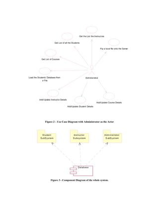
![This project adopted UML modeling techniques Figure 3 represents the component diagram of
for the design. The three kinds of UML models the whole system. The system consists of three
used to describe the component-based model of sub systems and a Database Component. The
this project are the Use-Case Diagrams, three sub systems, Student Sub System,
Component Diagrams and the Class Diagrams. Instructor Sub System and the Administrator Sub
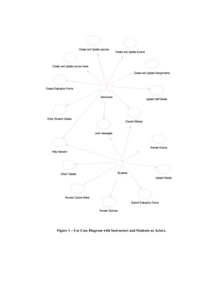
The design begins with the illustration of Use- System are dependent on the central Database
Case diagrams that represent the system and one Component.
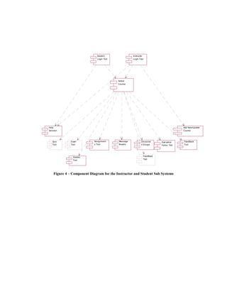
or more outside interactors (called actors), Figure 4 is the general representation of the
together with actions performed by the system. components involved in the whole System whose
Figure 1 illustrates the interaction of the top layer is the Students’ and the Instructors’
Instructors and the Students with the System. Interface.
Instructors are Students are the external entities The Instructors and the Students enter the
to the System who can log into the System and System through a Login Tool Component in the
use the functionality provided by the system. The first layer, and then the Select Course Tool
interaction between the Instructors and the Component in the second layer. The components
Students can take place in two modes; in the next layer of the hierarchy are dependent
Synchronous and Asynchronous modes. The on the session variables that are passed on from
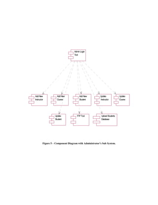
Synchronous interactivity is provided by the tools in the first two layers. Figure 5 is the
functionality offered by the tools like Course representation of the rest of the components
Delivery, Discussion Groups, Feedback tool and involved in the system whose top Layer is the
Help Session. The course delivery tool and the Administrators interface. A more detailed
help session tool are based on the Microsoft representation of the interfaces that form the first
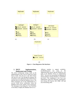
Netmeeting conferencing component. The layer in the figures 4 and 5 is represented in the
Feedback tool is part of Course delivery and is Figure 6.
intended to give the instructor immediate Figure 6 (a) - represents the class diagram of the
feedback on the impressions of the students Student's Interface in the Students Sub System to
during lecture delivery. These impressions the Select Course Tool. Figure 6 (b) - represents
include three faces: a smiley face, a doubtful the class diagram of the Instructor's Interface in
face, and a confused face. Quiz Tool, Grades the Instructor Sub System to the Select Course
Tool, Assignments Tool, etc provide support for Tool. Figure 6 (c) - represents the class diagram
asynchronous communication. Figure 2 of the Administrator's Interface in the
illustrates the interaction of the Administrator Administrator Sub System to the other
with the System. The Administrator is also an components in the Sub System.
external entity to the System who can log into Figure 6 (d) - represents the class diagram of the
the System and use the functionality provided by Select Course Tool, which is an interface
the System. The Use-Case Diagrams give an between the Students and the Instructors
overview of the System functionality and its Interface to the rest of the components in their
respective users from a Users’ perspective. A respective Sub Systems A class diagram is a
more detailed documentation of the design issues collection of (static) declarative model elements,
from a developer and a maintainer’s perspective such as classes, interfaces, and their
is the illustration of the Component diagrams. relationships, connected as a graph to each other
Component diagrams show the software and to their contents. A detailed class diagram
components that make up a reusable piece of representation of each of the components
software, their interfaces, and their represented in the above diagrams is documented
interrelationships. [6] in [7]
.
.
.](https://image.slidesharecdn.com/ammar1-120422104319-phpapp01/85/Ammar-1-2-320.jpg)
![The testing of Web-based applications has some performance problems in terms of unacceptable
similarity with the testing of desktop systems, network delays and degradation in the quality of
which involve the need to test the usual audio-video interactions.
functionality, configuration, and compatibility,
as well as performing all the standard test types. 5. References
However, Web application testing is more [1] Mark, J Pullen. The Internet-Based Lecture:
difficult because complexities are multiplied by Converging Teaching and Technology, ACM
all the commercial components that interact with Conference on Innovation and Technology in
the application. When an error is located in a Computer Science Education (ITiCSE), July
Web environment, its often difficult to pinpoint 2000.
where the error occurs. The behavior seen or the [2] NagaRaju, Bussa. WVU - Interactive Web
error message received may be the result of Based Distance Learning Tool, MSEE Thesis,
errors happening on different distributed Department of Computer Science and Electrical
components of the system and the error may be Engineering, West Virginia University,
difficult to reproduce. Web environments are December 1999.
dense with error-prone technology variables. The (http://etd.wvu.edu/ETDS/E1116/bussa_n_etd.pd
five fundamental considerations of Web- f)
application testing are: [3] Osama S. Abdalla, DBAdmin : A Web-
N When an error is flagged on the client based Application for Distance Education, A
side, it may be the symptom of an error Masters of Computer Engineering Problem
instead of the error itself. Report, Dept. of Computer Science and
N Errors may be environment-dependent Electrical Engineering, West Virginia
and may not appear in different University, December 1998.
environments. [4] AbdulMobeen Mohammad, WVUCT: A
N Errors may be in the code or in the Process Centered Environment for Distance
configuration. Education, MSEE Thesis, Dept. of Computer
N Errors may reside in any of several Science and Electrical Engineering, West
layers. Virginia University, March 1998.
N Examining the two classes of operating [5] The Unified Modeling Language,
environments - static versus dynamic - http://www.rational.com/uml/gstart/index.jsp.
demands different approaches. [6] Gomaa, Hassan “Designing Concurrent
The WICT prototype has been tested in the Lab Distributed, and Real-time Applications with
and the successful and failed test cases are UML, Object Technology Series, Addison
documented in [7]. Testing of the tool Wesley, 2000, ISBN 0-201-65793-7.
components on actual courses is yet to be [7] Lakshmi Bhetanabhotla, “Enhancements of
conducted. WICT”, A Masters in Computer Science
Problem Report, Dept. of Computer Science and
Electrical Engineering, West Virginia
4. Conclusions University, October 2000.
A UML software architecture model of a Web-
based Interactive Course Tool is proposed. The
architecture contains components to support
interactions between instructors and students.
These components include a help session
components and a course delivery components
base on NetMeeting, the Microsoft conferencing
tool. A simple prototype of the tool is
implemented, deployed and then tested. The
scalability of the proposed architecture can be
enhanced using a distributed component
architecture based on a broker framework such
as CORBA (Common Object Request Broker
Architecture). The broker services could be
utilized to develop an extensible architecture.
The use of a conferencing tool component for
student instructor interactions could pose](https://image.slidesharecdn.com/ammar1-120422104319-phpapp01/85/Ammar-1-8-320.jpg)

1. The document presents the UML architecture of a Web-based Interactive Course Tool developed at West Virginia University. 2. The tool provides components to support interactions between instructors, administrators, and students through online courses. 3. The architecture is modeled using UML diagrams including use case diagrams, component diagrams, and class diagrams to design the software system.