Downloaded 114 times

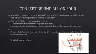


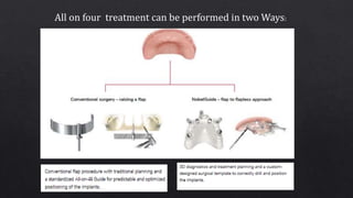

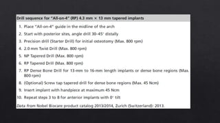
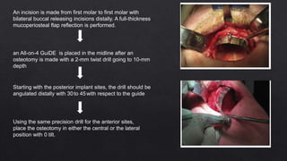
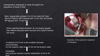
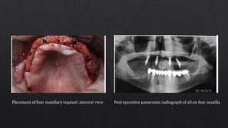

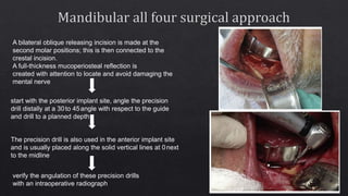
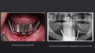
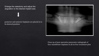
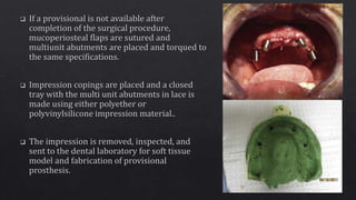
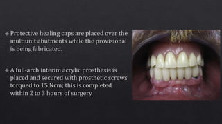
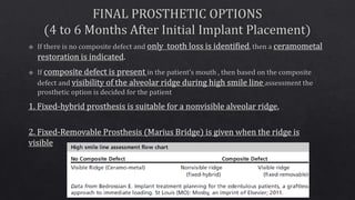
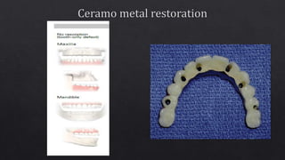
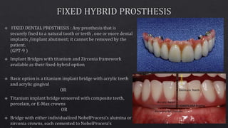

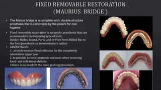
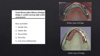
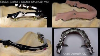
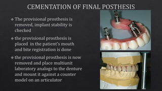
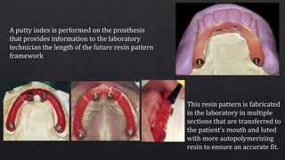
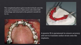
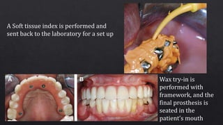
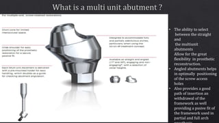
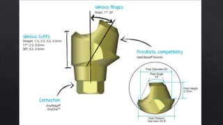
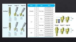
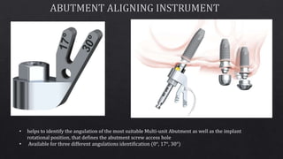
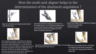


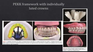
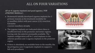
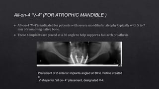
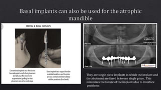
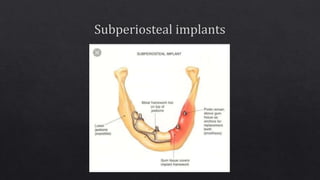


- The document discusses various techniques for all-on-4 and all-on-6 dental implant procedures, including the surgical placement of implants and fabrication of final prostheses. - Key steps include making incisions, reflecting tissue flaps, drilling osteotomies at angled positions, inserting implants, taking radiographs to confirm placement, attaching abutments, and creating temporary and final prostheses. - Options for bar attachments and different types of bridges to create fixed or removable restorations are also described. Proper angulation and positioning of implants is important for creating an accurate fitting framework.


