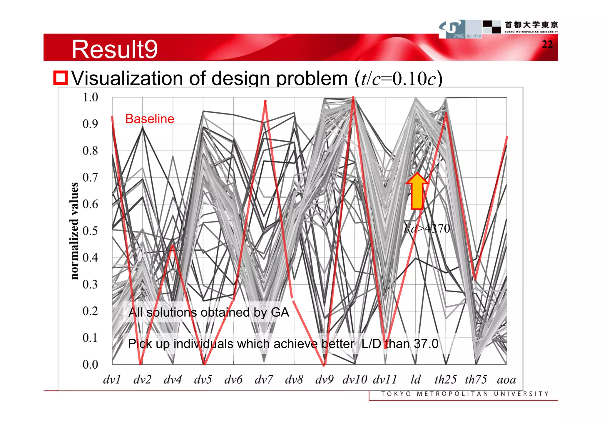
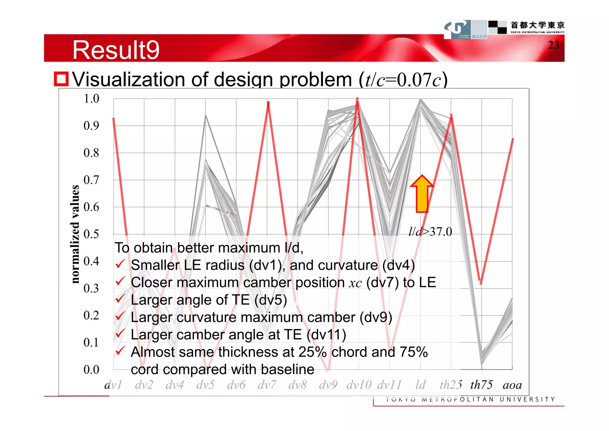
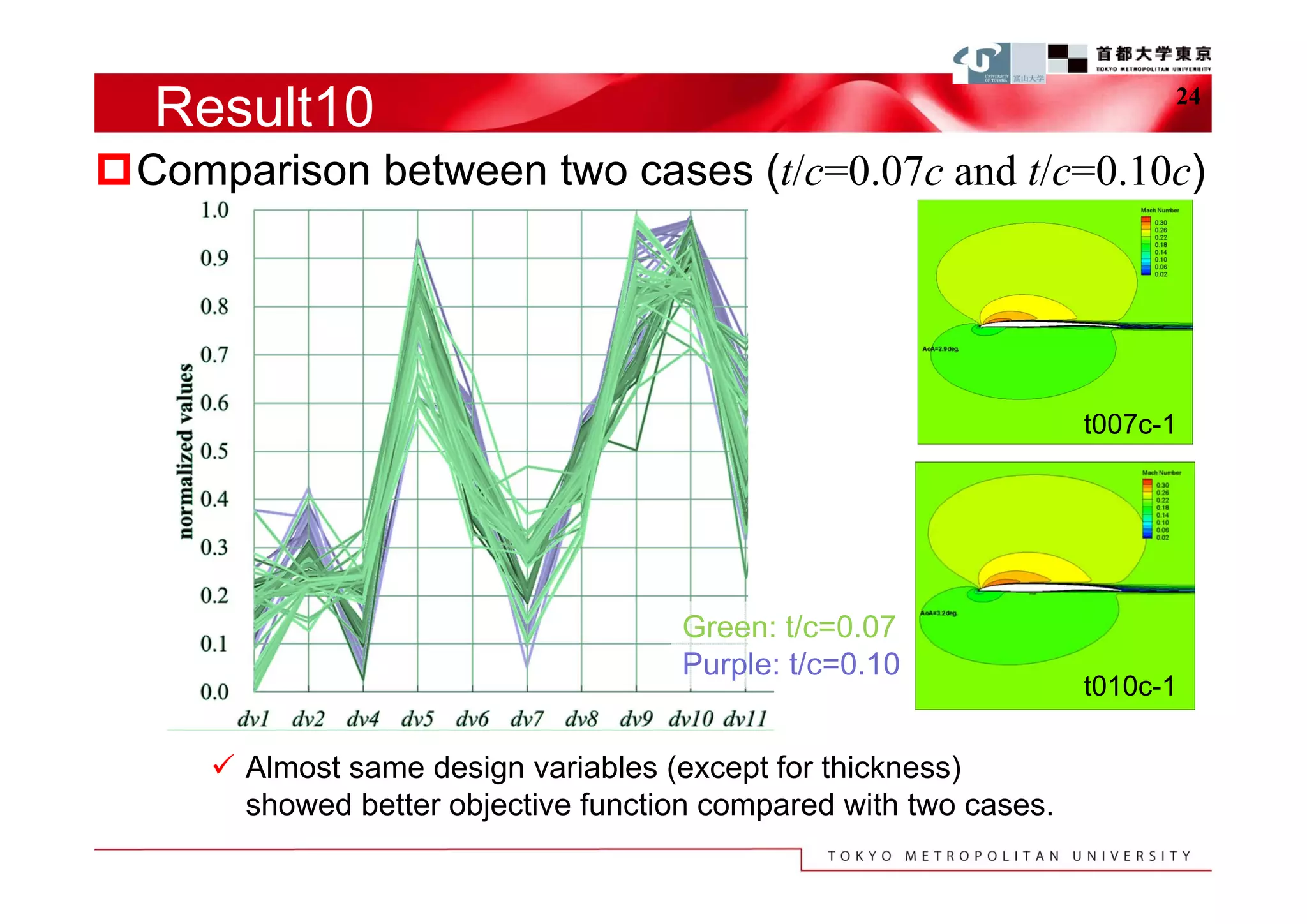
The document describes a study that used computational fluid dynamics and genetic algorithms to optimize airfoil designs for aircraft intended to fly on Mars. The study represented airfoils using a modified PARSEC method and evaluated designs based on their maximum lift-to-drag ratio. The optimization process produced designs with higher lift-to-drag ratios than the baseline design, achieving this through design changes like smaller leading edge radii, increased camber, and more relaxed upper surface pressure recovery. Visualization of the results provided insight into which design parameters most affected lift-to-drag ratio. The study demonstrated an efficient method for exploring unknown airfoil design problems to achieve higher performing designs for Mars aircraft.
![Background2 4
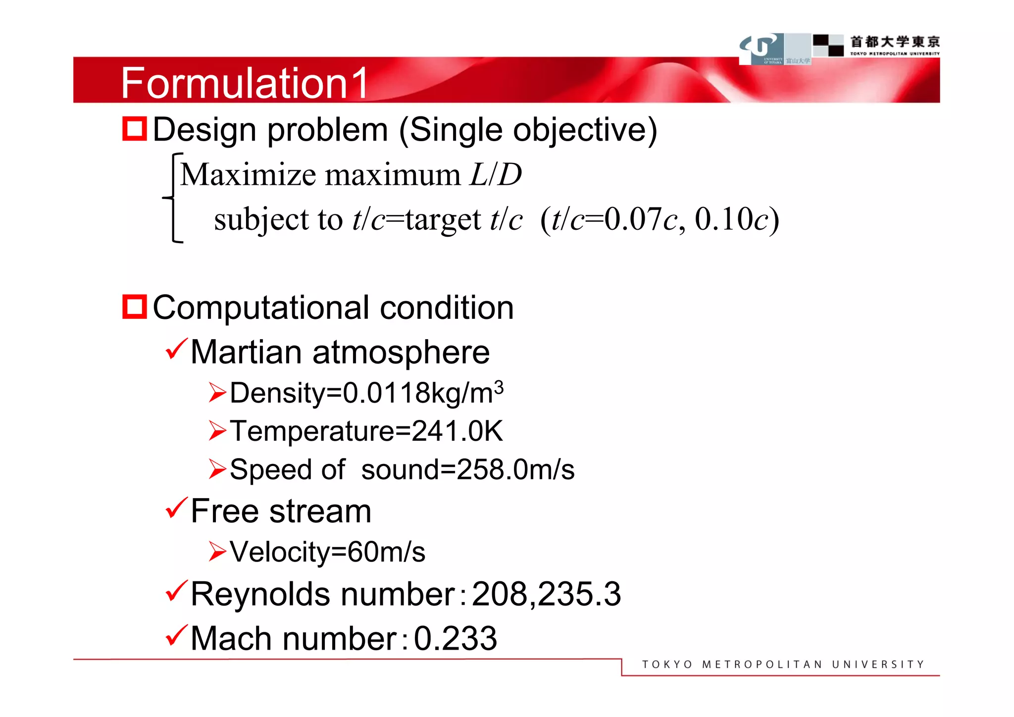
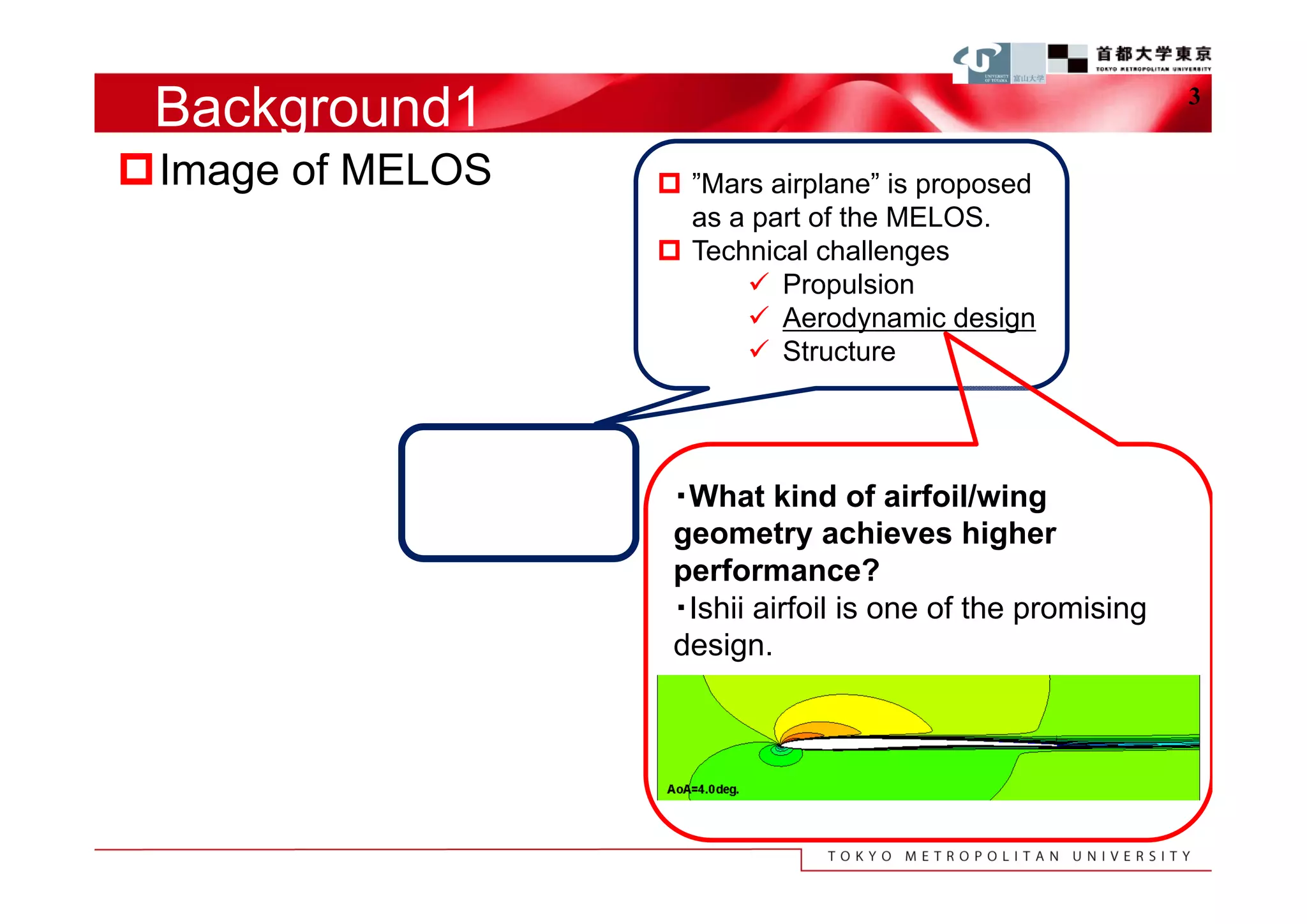
Difficulty of flight in the Martian atmosphere
gravity density Viscosity Sonic speed atmospheric
[m/s2] [kg/m3] [10-5Pa・s] [m/s] constituent
The Earth 9.8 1.17 1.86 345 N2,O2
The Mars 3.2 0.0118 1.36 258 CO2
1/3 gravity of the earth → Required lift is 1/3.
1% density of the earth → Lift is required to be
hundredfold increased.
⇒ Lift of the Mars-airplane have to be about 33rd
times lift as much as that of the Earth-airplane.
3/4 speed of sound → Compressibility should be
considered even for relative slow flight.
Knowledge has to be acquired for unknown design problem.
Efficient design method is required for Mars-airplane design.](https://image.slidesharecdn.com/icfdppt-121127054057-phpapp02/75/Airfoil-Design-for-Mars-Aircraft-Using-Modified-PARSEC-Geometry-Representation-4-2048.jpg)