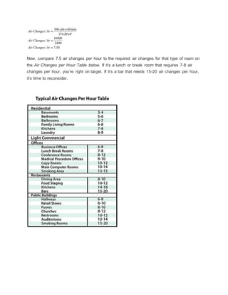
Best VIP Call Girls Noida Sector 44 Call Me: 8448380779
Airchanges hvac
1.
2.
3. Use the Air Changes Calculation to Determine Room CFM
An air change is how many times the air enters and exits a room from the HVAC system in one hour.
Engineering room airflow may present a real challenge when balancing an HVAC system.
Most calculations only use the heat loss or gain of a room to decide on required airflow and
often don’t take into consideration required room ventilation needs. Let’s take a look at how
an air change calculation may simplify this step in your air balancing.
What is an Air Change?
An air change is how many times the air enters and exits a room from the HVAC system in
one hour. Or, how many times a room would fill up with the air from the supply registers in
sixty minutes.
You can then compare the number of room air changes to the Required Air Changes Table
below. If it’s in the range, you can proceed to design or balance the airflow and have an
additional assurance that you’re doing the right thing. If it’s way out of range, you’d better
take another look.
The Air Changes Formula
To calculate room air changes, measure the supply airflow into a room, multiply the CFM
times 60 minutes per hour. Then divide by the volume of the room in cubic feet:
In plain English, we’re changing CFM into Cubic Feet per Hour (CFH). Then we calculate
the volume of the room by multiplying the room height times the width times the length.
Then we simply divide the CFH by the volume of the room.
Here’s an example of how a full formula works:
4. Now, compare 7.5 air changes per hour to the required air changes for that type of room on
the Air Changes per Hour Table below. If it’s a lunch or break room that requires 7-8 air
changes per hour, you’re right on target. If it’s a bar that needs 15-20 air changes per hour,
it’s time to reconsider.
5. Room CFM Formula
Let’s look at this engineering formula differently. For example, what if the airflow is unknown
and you need to calculate the required CFM for a room? Here is a four-step process on how
to calculate the room CFM:
Step One – Use the above Air Changes per Hour Table to identify the required air changes
needed for the use of the room. Let’s say it’s a conference room requiring 10 air changes
per hour.
Step Two - Calculate the volume of the room (L’xW’xH’).
Step Three - Multiply the volume of the room by the required room air changes.
Step Four Divide the answer by 60 minutes per Hour to find the required room CFM:
Here’s an example of how to work the formula:
When designing or balancing a system requiring additional airflow for ventilation purposes,
remember this room will normally demand constant fan operation when occupied. This may
present a problem for other rooms on the same zone, so take that into consideration.
Many of these rooms may require a significant amount of outdoor air. The BTU content of
this air has to be included in the heat gain or heat loss of the building when determining the
size of the heating and cooling equipment.
Practice these calculations several times in the shop or office. Then do the calculations in
the field several times over the next week to check airflow in rooms with uncommon
ventilation requirements. Study the Air Changes per Hour Table to become familiar with the
rooms that need more ventilation than the heating or cooling load requires.
6. Rob “Doc” Falke serves the industry as president of National Comfort Institute, an
HVAC-based training company and membership organization. If you're an HVAC contractor
or technician interested in a free Air Changes Calculation Procedure, contact Doc
atrobf@ncihvac.com or call him at 800-633-7058. Go to NCI’s website
atnationalcomfortinstitute.com for free information, articles, and downloads.
Why does the cfm per ton of air conditioning vary?
QUICK ANSWER
The cubic foot per minute, or cfm, per ton of air conditioning varies depending on
application. Approximately 400 cfm is required for normal use, while 500 cfm is needed
for high sensible heat situations. High latent heat loads use 350 cfm. Sensible heat
directly affects the temperature of the room, while latent heat does not affect
temperature because it causes a change in state.
CONTINUE READING
FULL ANSWER
An air conditioner's cfm rating describes the volume of air, in cubic feet, that flows
through the unit in one minute. A/C units in high sensible heat environments run at
higher cfm values because of the increased cooling load. With normal cooling loads, the
A/C unit requires approximately 7.5 air changes per hour to maintain a comfortable
environment.
With an increased cooling load, the required amount of air changes increases to
approximately 10 per hour, which is achievable because the A/C unit moves more air
per minute. An A/C's sensible capacity describes the ability to remove sensible heat and
lower the temperature of the air. An A/C's latent capacity is its ability to remove latent
heat from the air. This removes humidity by causing water vapor in the air to
condensate. If the air speed is too fast, the accumulated condensate is blown off the
fins of the A/C's evaporator and back down the duct, which is why units in environments
with high latent heat run at lower cfm values.
What is a Duct CFM calculator?
7. QUICK ANSWER
A duct calculator measures air velocity by using a formula in which air flow is a variable
expressed in cubic feet per minute, or CFM. Heating, ventilation and air conditioning
professionals commonly use duct calculators.
CONTINUE READING
FULL ANSWER
Air velocity is the measurement of the speed of the air flow, while air flow is the
measurement of the volume of air at a specific point. Determining the velocity of air as it
moves through duct work or pipe depends on multiple variables including duct size
measurements, duct area and air flow. While calculators express air flow in cubic feet
per minute, they express air velocity in linear feet per minute, or LFM.
How does CFM measure airflow?
QUICK ANSWER
Cubic feet per minute, or CFM, is calculated by using a combination of air velocity and
volume measurements. CFM is usually used to measure how much air flows through a
given heating or cooling system in a set amount of time.
CONTINUE READING
FULL ANSWER
Air velocity is measured in linear feet per minute, or LFM, and can be measured as air
passes through an air duct. By multiplying this number by the volume of the duct in
cubic feet, a CFM measurement is obtained. Because air ducts may change size from
point to point, these measurements should be taken over a few areas and then
averaged to get an accurate CFM measurement.
What is a CFM bathroom fan?
QUICK ANSWER
The CFM rating of a bathroom fan is a measurement of how many cubic feet of air it can
ventilate out every minute. To vent a bathroom properly, the bathroom fan must have a
CFM rating that is able to change the air eight times every hour.
CONTINUE READING
8. FULL ANSWER
According to the Home Ventilating Institute, a bathroom fan's CRM rating should match
up to the square footage of a bathroom. Any bathroom measuring less than 50 square
feet requires at least a 50-CFM bathroom fan. Larger bathrooms require more CFM so
that the air inside does not become filled with excess moisture, odors and humidity.
How can you calculate the CFM for an exhaust fan?
To calculate the minimum cubic feet per minute rating needed for an exhaust fan,
multiply the bathroom's length, width and height, and then multiply that result by
0.13. The final answer is the minimum CFM rating for the fan.
CONTINUE READING
FULL ANSWER
For instance, if a bathroom is 10 feet long, 8 feet wide and 9 feet tall, the volume of the
room is 720 cubic feet. When that is multiplied by 1.3, the result is 93.6. Therefore, the
minimum CFM rating needed is about 94. This formula is appropriate for bathrooms with
one sink and one shower head. If a room has more, the exhaust fan needs to be more
powerful to deal with the increased air flow.
There is also a rule of thumb to estimate the CFM rating needed. This uses the area of
the room, which is found by multiplying its length by its width. A bathroom that is 50
square feet or less needs a 50 CFM fan. With larger rooms, at least one CFM for each
square foot is required. Therefore, a bathroom with an area of 70 square feet needs a
fan with a minimum CFM rating of 70.
Fan ratings typically run between 50 and 110 CFM. The appropriate-size fan for a
bathroom can replace the room's air eight times in one hour.
How does a bathroom fan vent eliminate humidity?
QUICK ANSWER
A bathroom exhaust fan reduces humidity by drawing humid air out of the room and
replacing it with drier air from other areas. In a well-designed vent system, the air the
fan removes exits the house through a duct.
FULL ANSWER
Makeup air replaces what the fan pulls from the bathroom. Makeup air comes from
many places. If the bathroom is located on an outside wall, the vacuum the fan creates
pulls fresh air from around the cracks at the baseboard and from around window
frames. If the vacuum is unable to replace the air from an outside wall, it draws air
through the crack between the door and floor. The air the fan pulls from other parts of
the home also requires replacement, which occurs through small openings in outside
9. walls. If the installer does not seal the fan properly, the air enters the room from the attic
through openings around the fan, creating a small circulation pattern and reducing its
effectiveness at removing humidity.
Reducing humidity in a bathroom helps to prevent mold growth. Small bathrooms are
more susceptible to humidity than larger ones, especially if they include a shower or the
ceiling is uninsulated. In these small spaces, installing and using a vent fan regularly,
along with providing adequate insulation helps to eliminate humidity problems.
Calculating Fan Requirements
URBANGARDENMAGAZINE.COM
(Note: URBANGARDENMAGAZINE.COM is no longer in business)
We asked two experienced growers (Dan from Oregon and Fred from The
Netherlands) to face off with their different opinions on how to calculate your fan
requirements. Whose method do you think is the best?
Dan's Method
Calculating By Room Volume
You will find many calculations on the web for sizing a fan for ventilating indoor
gardens; however, what many of these calculations fail to take into consideration is the
friction loss on carbon filters and increased temperatures from HID lights. So here's my
calculation method which you can use as a guide for sizing an exhaust fan for a
growing area (keep in mind that this calculation will give you the lowest required CFM
(Cubic feet of air per minute) required to ventilate the indoor garden.)
Step 1: Room Volume
First the volume of the room needs to be calculated. To calculate multiply length x
width x height of growing area e.g. A room that is 8' x 8' x 8' will have a volume of 512
cubic feet.
Step 2: CFM Required
Your extraction fan should be able to adequately exchange the air in an indoor garden
once every three minutes. Therefore, 512 cubic feet / 3 minutes = 171 CFM. This will
be the absolute minimum CFM for exchanging the air in an indoor garden.
Step 3: Additional factors
Unfortunately, the minimum CFM needed to ventilate a indoor garden is never quite
that simple. Once the grower has calculated the minimum CFM required for their indoor
10. garden the following additional factors need to be considered:
Number of HID lights — add 5% per air cooled light or 10-15% per non-air cooled light.
CO2: add 5% for rooms with CO2 enrichment
Filters: if a carbon filter is to be used with the exhaust system then add 20%
Ambient temperature: for hot climates (such as Southern California) add 25%, for
hot and humid climates (such as Florida) add up to 40%.
An Example
In our 8' x 8' room we have 2 x 1000w air cooled lights, and we plan to use a carbon
filter. We also plan to use CO2 in this room. The ambient temperature is 90 °F (32°C),
however, we will be using air from another room that is air-conditioned. Here's the
minimum required CFM to ventilate room:
1) Calculate the CFM required for room (see above.)
2) Add 10% (for 2 air cooled lights.)
3) Add 5% of original CFM calculation (For CO2.)
4) Add 20% of original CFM calculation for Carbon Filter.
5) Air is coming from air-conditioned room so no need to add any other percentages.
6) CFM = (171 CFM) + (171CFM x 10%) + (171 CFM x 5%) + (171CFM x 20%) + ( 0
)= 231 CFM.
This is the absolute minimum CFM required to ventilate your room.
The next step might seem to match the closest fan to this CFM. However, for this
example I'd choose a six inch fan with a CFM of around 400 or more, and a 6 inch
carbon filter to match. The extra CFMs may seem a bit excessive (calculations on most
indoor gardening websites would recommend a 4" fan and a 4" c arbon filter) but it's
always better to over-spec since we need to compensate for air resistance in ducting
too.
Also, as we are using a carbon filter we will need to match the fan with the filter so that
the fan that will neatly fit onto the filter.
If all the variables are kept the same and we changed the room size from 8' x 8' to a
12' x 12' then the minimum required CFM would be 519 CFM.
The All-Important Inflow!
An intake port can be anything from a gap under the door to an open window - even a
11. hole in the wall. The best place for an intake port is diagonally opposite from your
exhaust fan; that way, air has to pass across the entire room - very efficient. You can
put a piece of screen over the opening to keep insects and animals out, a piece of A/C
filter to keep dust out, or a louvered shutter or backdraft damper that opens when the
fan turns on and closes when it turns off. You can also use a motorized damper. This
gets installed in-line with your ducting and is plugged into whatever device controls
your exhaust fan. When your fan turns on, it allows air to pass. When your fan shuts
off, it seals completely, preventing CO2, air, etc. from passing. You can get creative
with these devices and use one fan to control two rooms, etc.
One additional note about intake ports - you will see much better results from your
exhaust system if you install a second fan to create an active (as opposed to passive)
intake system. Normally, when your exhaust fan sucks air out of your room, air is
passively going to get sucked back into the room. By installing a second fan on the
intake side, you will reduce the amount of negative pressure created in the indoor
garden, thereby cutting down greatly on the amount of work the exhaust fan has to do
and allowing much more air to pass through. If you're not sure or you don't want to
spend the money, start out with just an exhaust fan. If it's not performing as well as
you thought it would, try adding an intake fan - you'll smile when you see the
difference!
Fred's Method
Calculating By Wattage
Hello there. First off, I'm used to working with Celsius, not Fahrenheit, but I've done
my best to provide formulas for both. My method for calculating fan requirements does
not cover active cooling with air conditioning systems or cool-tube designs. We're
talking about everyday grow chambers here, totally enclosed for airflow control, with
no large amounts of radiant heat into or out of the box. Your mileage may vary some
for these reasons.
RIGHT THEN, LET'S GET STARTED:
1) Start at the beginning and design this right! Before you even buy or cut anything for
your new project, determine the highest temperature that your intake air will ever be
when lights run. Call this T (inlet).
2) Use these formulas to determine difference in temperature you can tolerate. 80°F
(27°C) is just about the optimal for growing most plants. You can go up to 86°F (30°C)
if you have to, but aim for 80°F (27°C).
Tdiff = 27 °C – T (temperature of inlet air)
3) Add up wattage for all power sources in your indoor garden. Lights, pumps, heaters,
humidifier, radio, coffee maker, whatever! Add it ALL up and call it Watts. If it is on for
more than three minutes and uses more than a watt, add it up. This will make your
number worst-case and therefore a conservative value.
4) Compute the absolute minimum fan power you will need using the following
12. formulas. Fan power is measured in the amount of air (cubic feet) shifted per minute.
The formula below is the minimum fan rating you must have to achieve your
temperature goals. You will have to increase fan power to compensate for duct
constriction, small inlets, carbon scrubbers, screens, or other items that block airflow.
CFM = 1.75 x Watts /Tdiff (in Celsius)
If you prefer to work in Fahrenheit, try this formula:
CFM = 3 x Watts / Tdiff (in Fahrenheit)
5) Get at least this fan power or don't come and ask questions! If you are going to
have more than one fan, they should be mounted side-by-side rather than inline if you
want to add their different CFM ratings. For inline fans, use the lowest airflow rating of
all fans in the path. A fan on the inlet and a fan on the exhaust of the box are
considered inline fans. Fans just circulating air inside the indoor garden should not be
counted for airflow but must be included in your initial wattage calculations.
OK, TO SEE THESE FORMULAS IN ACTION WE'RE GOING TO HAVE TO DO A
LITTLE NUMBER CRUNCHING:
An Example
Ok, let's say you have 2000 watts in a 8 foot by 8 foot room with an 8 foot ceiling
height.
So what amount of air do I need to move to keep the room at 82°F (28°C)? My
incoming air temperatures are 68°F (20°C) during the lights on period.
Tdiff = 28 – 20 = 8°C
For Celsius the formula comes out at:
CFM = 1.75 x 2000 / 8 = 438 CFM
For Fahrenheit we get the following:
Tdiff = 82 – 68 = 14°F CFM=3x2000/14=429 CFM
Remember, Tdiff shows how much your temperatures will rise above your inflow air
temperature for a given wattage and air movement.
If you are adding any carbon scrubbers or extensive ductwork, this is where you add to
the fan size to account for air pressure losses. You have to move this many CFM, or the
numbers don't come out right. Exactly how much these items diminish your airflow
depends on your exact configuration and is beyond the scope of this introductory
article!
What to do when your outside temperatures are higher than your maximum allowed
indoor garden temperatures!
13. YOU HAVE A FEW CHOICES:
1) Stop growing for a while till things cool off or try running your grow lamps at night
when inlet air will be cooler.
2) Reduce your lighting to drop the heat load. Not good if the incoming air is already
over critical when it arrives in the box. Might be possible if the inlet air temperature is
lower but you are running too many lights to keep up with the cooling.
3) Use active air conditioning.
Okay, there you have it – two very different approaches to calculating your
extraction requirements. What do you think? Do you prefer either or neither of
these approaches? Or perhaps a combination of the two?
My Simple Rule of Thumb
IF YOU WANT TO KEEP THINGS REALLY SIMPLE, JUST REMEMBER THAT YOU
WANT TO REPLACE THE AIR IN YOUR INDOOR GARDEN EVERY ONE TO THREE
MINUTES. IF YOU'RE IN A HOT AREA, EXCHANGE IT EVERY MINUTE; IF YOU'RE
IN A COOLER AREA, YOU CAN TAKE UP TO THREE MINUTES.
A Comment from Patrick King, the president and owner of Chillking Chillers....
If you are going to discharge from a room you must have "make up air". The intake for
exhausted air needs to be 20% larger than the discharge air. Otherwise it will draw air
throughout the structure. I have seen buildings with dust lines on the floor near the
wall. This is from air intaking along the walls edge on the floor, it escapes through the
air gaps. This can cause a great load on air conditioned buildings. This suction will draw
air from anyplace it can. Most structures are fairly airtight, however there is always
small air gaps along the base plate of the walls. A fine dust will be pulled into the
building, the worst part is that this dust is very bad for asthma patients or others with
allergies and breathing disorders.
14. Engineering Formulas
Nominal Design Parameters
Chillers: 2.4GPM/Ton @ 10° F ∆T Flow
Rate
12,000 BTU/HR/Ton
20° F - 60° F Standard Supply
Range
Rating at 50° F Supply
Temperature
85° F Water Cooled
Condenser
95° F Air Cooled Condenser
Cooling Tower = 15,000 BTU/HR/Ton
3 GPM per Ton
85° F Leaving Water Temperature
95° F Entering Water Temperature
78° F Wet Bulb
Tower water make-up requirements: Untreated 2% of flow rate Treated 1.5% of flow rate
Weighted Water Test
Chiller Ton = GPMx∆T (Delta Temp)
24
Tower Ton =GPMx∆T (Delta Temp)
30
Chiller Sizing
Injection Molding Blow Molding Extrusion
30#/hr H.D. Polyethlene= 1ton
40#/hr Polyolefins= 1
ton
50#/hr H.D. Polyethlene = 1 ton
35#/hr L.D. Polyethlene = 1ton 40#/hr PET= 1 ton 50#/hr L.D. Polyethlene = 1 ton
35#/hr Polypropylene = 1ton
Minimum Flow 04.8
gpm/ton
50#/hr Polypropylene = 1 ton
45#/hr PVC = 1 ton 75#/hr Polystyrene = 1 ton
50#/hr ABS= 1 ton 75#/hr PVC = 1 ton
50#/hr Polystyrene= 1 ton Blown Film Air Ring Cooling
105 CFM (50 ° F @ 78° F WBT)= 1 ton
40#/hr Nylon= 1 ton
35#/hr Acrylic= 1 ton
40#/hr Polyurethane= 1 ton
50#/hr Acetal= 1 ton
40#/hr PPO= 1 ton
40#/hr PET= 1 ton
50#/hr Polycarb= 1 ton
Chiller Capacity Loss/Gain
Decrease nominal tonnage by approximately 2% per degreebelow a 50 ° F leaving water
temperature.
Increase nominal tonnageapproximately 2% per degree above 50 ° F leaving water
temperature up to 55 ° F
Other Equipment
Air Compressor w/no after cooler=.1 ton/Hp
Air Compressor w/after cooler=.2 Ton/Hp
15. Vacuum Pump=.1 ton/Hp
Hydraulic Cooling=.1 ton/Hp
Barrel Cooling=.1 ton/in screw Dia.
Hot Runner Mold= 1 ton/10.5KW
Water Pump in Circuit=.2 Ton/Hr
Feed Throat
400Ton Machine or above1 Ton
Below 400 Ton - 1/2 Ton
Extrusion Equipment
Gear Box Cooling=1 Ton/100Hp
Feed Throat 3" Screw or Less=1 Ton
Above 3" Screw=2 Tons
Barrel or Screw Cooling=1 Ton/Inch of Screw Diameter
Pipe Sizing Guide
(Based on 5' - 7' feet/second velocity)
1/8” = .75 GPM 3/4" = 10 GPM 2" = 70 GPM 6" = 600 GPM
¼” = 1.5 GPM 1" = 15 GPM 2 1/2" = 100 GPM 8" = 1,000 GPM
3/8” = 3 GPM 1 1/4" = 30 GPM 3" = 150 GPM 10" = 3000 GPM
1/2" = 6 GPM 1 1/2" = 40 GPM 4"= 275 GPM 12" = 5000 GPM
Metric Conversion Chart
To Convert To Convert
Unit Volume Power
US GPM Liters/Min3.785 FT/Lb/SEC Watts 1.356
US GPM Cum/Hr .2271 KW BTUH 342
CFM Liters/Min28.317 Boiler HP BTUH 33475
CFM Cum/hr 1.6992 HP BTUH 2545
Unit Weight HP KW .7457
Lb/Ft Kg/m 1.4881
Lbs/Sq
in
gr/sq cm 70.31 Heat
Lbs/Sq
in
kPA 6.894 BTU Kg-cal .252
Lbs/Sq
in
Kg/Sq
Cm
.07031 BTU/LB Kg-cal .5556
Lbs/Sq
in
gr/cu cm 27.68 BTU/SQ FT
gr-cal/sq
cm
.2713
Length BTU/CU FT
Kg-
cal/Cum
8.899
Inches cm 2.540 Weight
Feet meters .3048 Grains grams .0648
Yards meters .9144 Ounces* grams 28.350
Miles km 1.609 LBS kg .4536
Volume US tons kg 907.2
16. Cu.
Inches cu cm 16.387 US Tons Tonnes .9072
Cu.
Inches
liters .01639 Long Tons kg 1016
Cu Feet cu meter .02832 Area
Cu Feet liters 28.317 SQ Inches sq cm 6.452
Cu Yearscu meters .7646 SQ Years
sq
meters
.8361
Fl
Ounces
cu cm 29.57 SQ Miles sq km 2.590
US
Gallon
cu meters .003785
US
Gallon
liters 3.785
*Auoirdupois pounds and ounces
Temperature
°F °C °F °C °F °C °F °C
0 -17.8 35 1.7 15 -9.4 50 10.0
5 -15 40 4.4 20 -6.7 55 12.8
10 -12.2 45 7.2 30 1.1 60 15.6
°F to °C = (°F - 32) x .55 =°C °C to °F = (°C x 1.8) + 32 =°F
Flow Rate Vs. Temp Differences Per Ton % Ethylene Glycol by VolumevsFreeze Protection
1.2 GPM = 20 °F T 10% 25°F
2.4 GPM = 10 °F T 20% 15°F
4.8 GPM = 5 °F T 30% 0°F
9.6 GPM = 2.5 °F T 40% -15°F
50% -40°F
Abbreviations, Equivalents & Formulas
T = Delta Temperature = Temperature Differential
PSI = Poundsper square inch 1 Cooling Tower Ton= 15,000BTU/HR
GPM = Gallonsper Minute 1 Refrigerant Ton = 12,000 BTU/HR
EWT = Entering Water Temperature 1 Gallon = 8.33 lbs(water)
LWT = Leaving Water Temperature 1 Cubic Foot = 7.48 gallons
BTU = British Thermal Unit 1 Mil = .001"
BTU/HR = GMP x 500 x . T (water) 1 Bar = 14.7 PSI
1 HP = 2544 BTU/HR 1 KW = 3413 BTU/HR
Ft. H.D. = PSI x 2.31 1 KW = 1.34 HP
Q=4.5 x CFM x H = BTUH (Air Cooling) PSI= Ft of head/2.31
Pump HP= . GPM x P (Ft.H.D) .
3960 x (0.65 to 0.75) (Pump Eff)
KW = Ampsx Voltsx 0.85 x 1.73
1,000
Head in Feet to PSI Conversions calculator
Filtration Chart
Mesh Micron Inches Mesh Micron Inches
4 5205 0.2030 80 177 0.0070
8 2487 0.0970 100 149 0.0059
10 1923 0.0750 120 125 0.0049
14 1307 0.0510 140 105 0.0041
18 1000 0.0394 170 88 0.0035
20 840 0.0331 200 74 0.0029
25 710 0.0280 230 62 0.0024
17. 30 590 0.0232 270 53 0.0021
35 500 0.0197 325 44 0.0017
40 420 0.0165 400 37 0.0015
45 350 0.0138 550 25 0.0009
50 297 0.0117 800 15 0.0006
60 250 0.0098 1250 10 0.0004
70 210 0.0083 5 0.0002
General sizing formula:
1. Calculate Temperature Differential (?T°F) ?T°F = Incoming Water Temperature (°F) - Required
Chill Water Temperature
2. Calculate BTU/hr. BTU/hr. = Gallons per hr x 8.33 x ?T°F
3. Calculate tons of cooling capacity Tons = BTU/hr. ÷ 12,000
4. Oversize the chiller by 20% Ideal Size in Tons = Tons x 1.2
5. You have the ideal size for your needs
For example, what size chiller is required to cool 40GPM from 70°F to 58°F?
1. ?T°F = 70°F - 58°F = 12°F
2. BTU/hr. = 40gpm x 60 x 8.33 x 12°F = 239,904 BTU/hr.
3. Ton Capacity = 239,904 BTU/hr. ÷ 12,000 = 19.992 Tons
4. Oversize the chiller = 19.992 x 1.2 = 23.9904
5. A 23.9904 or 25-Ton chiller is required
Process Cooling System Chiller and Tower
Sizing Formulas
TOWER SYSTEM DESIGN FORMULAS
Cooling Tower = 3 Gallons per Minute per ton
1 Tower Ton = 15,000 BTU/hr
Tower Ton = GPM x ΔT/30
CHILLER SYSTEM DESIGN
18. Chiller = 2.4 Gallons per Minute / ton
1 ChillerTon = 12,000 BTU / hr
Chiller Ton = GPM x ΔT / 24
LOAD SIZING FOR INJECTION MOLDING APPLICATIONS : MATERIAL
30# / hr H.D. Polyethylene = 1 ton
35# / hr L.D. Polyethylene = 1 ton
35# / hr Polypropylene = 1 ton
45# / hr PVC = 1 ton
50# / hr ABS = 1 ton
50# / hr Polystyrene = 1 ton
40# / hr Nylon = 1 ton
35# / hr Acrylic = 1 ton
40# / hr Polyurethane = 1 ton
50# / hr Acetal = 1 ton
40# / hr PPO = 1 ton
40# / hr PET = 1 ton
50# / hr Polycarb = 1 ton
LOAD SIZING FOR INJECTION MOLDING APPLICATIONS : MACHINE
Hydraulics = .1 ton/Horsepower
Feed Throat = 1/2 ton each
LOAD SIZING FOR EXTRUSION APPLICATIONS : Pipe, Profile, and Sheet
MATERIAL
50# / hr H.D. Polyethylene = 1 ton
50# / hr L.D. Polyethylene = 1 ton
50# / hr Polypropylene = 1 ton
75# / hr Polystyrene = 1 ton
70# / hr PVC = 1 ton
MACHINE
Extruder Barrel = 1 ton/inch of screw diameter
Gear Box = 1 ton / 100 HP
Feed Throat : diameter is < 3" = 1 ton
19. Feed Throat : diameter is > 3" = 2 ton
Air Ring Cooling @ 105 CFM = 1 ton (50°F air @ 78°F WBT)
LOAD SIZING FOR BLOW MOLDING APPLICATIONS
MATERIAL
40# / hr Polyolefins = 1 ton (minimun Flow is 4.8 GPM / ton)
MACHINE
Hydraulics = .1 ton / inch
Feed Throat = 1/2 ton
LOAD SIZING FOR OTHER EQUIPMENT
Air Compressors with no after cooler = .1 ton / HP
Air Compressor with after cooler = .2 ton / HP
Vacuum Pump = .2 ton / HP
Machine Tools = .2 ton / HP
Water-Cooled Chiller = Each ton of chiller requires 1 ton of cooling tower
Mold Temperature Controllers = 1.2 ton per zone + .2 ton/horsepower (heating)
Mold Temperature Controllers = use PPH chart + .2 ton/horsepower (cooling)
Spot Welders = 1/4 ton per tip (for chilled water)
Plating Baths = Heat removal (BTU / hr) = DC amps x DC volts x 2.56
Mold Room Heating = 25 BTU / sq.ft. with 16' ceiling
Non Mold Room Heating = 50 BTU / sq.ft. with 16' ceiling
Mold Room Air Conditioning = 80 sq.ft / ton with 16' ceiling
LOAD SIZING FOR DIE CASTING
Zinc = Heat removal (BTU / hr) = M x 95 BTU / lb
M = throughput rate (lbs / hr)
Pour at 800°F
Remove at 300°F
Aluminum = Heat removal (BTU / hr) = M x 325 BTU / lb
M = throughput rate (lbs / hr)
Pour at 1200°F
Remove at 900°F
CHILLER CAPACITY LOSS
For each 1°F below 50°F LWT = 2% loss of rated chiller capacity
20. CHILLER HEAT LOAD & WATER FLOW
The flow rate necessary to deliver the full output of the heat source at a specific temperature
drop can be found using equation below:
Q = H / (8.01 x ρ x c x ▲T)
Where:
• Q= Water volume flow rate (GPM)
• H = Heat load (Btu/hr)
• ▲T = Intended temperature drop (°F)
• ρ = Fluid's density at the average system temperature (lb/ft3)
• c = the fluid's specific heat at the average system temperature (Btu/lb/°F)
• 8.01 = a constant
In small to medium size hydronic systems, the product of (8.01 x ρ x c) can be taken as 500 for
water, 479 for 30% glycol, and 450 for 50% glycol. The total heat removed by air condition
chilled-
water installation can thus be expressed as
H = 500 x Q x ▲T
Where
• H = total heat removed (Btu/h)
• Q = water flow rate (gal/min)
• ▲T = temperature difference ( 0F)
21. Evaporator Flow Rate
The evaporator water flow rate canbe expressed as
Qe = Htons x 24 / T
Where
• Qe = Evaporator water flow rate (GPM)
• Htons = Air conditioning cooling load (tons)
• T = Temperature differential between inlet and outlet (°F)
Condenser Flow Rate
The condenser water flow rate can be expressed as
Qc = Htons x 30 / ▲T
Where
• Qc = Condenser water flow rate (GPM)
• Htons = Air conditioning cooling load (tons)
• ▲T = Temperature differential between inlet and outlet (°F)
Note the equation above assumes 25% heat of compression.
CONDENSATEGENERATION
Condensate generation in an air condition system where specific humidity before and after are
known can be expressed as
Q Cond = Q air x W Lb / (SpV x 8.33)
Q Cond = Q air x W GR / (SpV x 8.33 x 7000)
Where
22. • Q Cond = Air Conditioning condensate generated (GPM)
• Q air = Air Flow Rate through the air-handling unit cooling c oil (Cu-ft / minute)
• SpV = Specific Volume of Air (Cu-ft per lb of dry air)
• W Lb = Specific Humidity diff. between inlet and outlet of air stream across coil (lb-H2O per
lb of dry air)
• W GR = Specific Humidity diff. between inlet and outlet of air stream acros s coil (Gr. H2O per
lb of dry air)
FLOW RATES IN HEATING SYSTEMS
The volumetric flow rate in a heating system can be expressed by the basic equation:
Q = H / (Cp x ρ x ▲T)
Where
• Q = volumetric flow rate (GPM)
• H = heat flow rate (Btu/hr)
• CP = specific heat capacity (Btu/lb-°F)
• ρ = density (lb/ft3 )
• ▲T = temperature difference (°F)
The basic equation can be expressed for water with temperature 600F flow rate as:
Q = H (7.48gal/ft3 ) / ((1 Btu/lb- 0F) (62.34 lb/ft3 ) (60 min/h)▲T)
Or
Q = h / (500 x ▲T)
Where
• Q = Water flow rate (GPM)
23. • H = Heat flow rate (Btu/hr)
• ▲T = Temperature difference (0F) (usually 20ºF)
For more exact volumetric flow rates for hot water the properties of hot water should be used.
Water Mass Flow Rate Water mas s flow can be express ed as:
m = h / ((1.2 Btu/lb- 0F) x ▲T)
Where
• m = mass flow (lb/hr)