CT16IGBD2.2
I1
I
1.0 RIDUTTORI UNIVERSALIA VITE SENZA FINE
WORM GEARBOXES
SCHNECKENGETRIEBE
WI
WMI
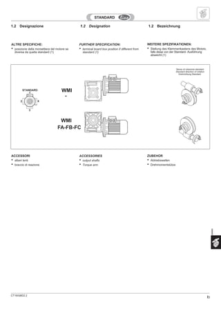
1.2 Designazione Designation Bezeichnungen I2
1.4 Lubrificazione Lubrication Schmierung I4
1.5 Carichi radiali e assiali Axial and overhung loads Radiale und Axiale Belastungen I6
1.6 Prestazioni riduttori Gearboxes performances Leistungen der Getriebe I9
1.8 Dimensioni Dimensions Abmessungen I13
1.9 Accessori braccio di rezione Accessories torque arm Zubehör Drehmomentstütze I17
1.10 Accessori alberi lenti Accessories output shafts Zubehör Abtriebswellen I17
1.11 Cappellotto Cover Deckel I18
Pag.
Page
Seite
WMI
WI
2.
I2
Grandezza
Size
Größe
Versione
Version
Ausführung
ir IEC
Tipo
Type
Typ
Grandezza
Size
Gröe
Lunghezza
Lenght
Länge
[*1] [*2][*3]
25
30
40
50
63
75
90
110
130
150
-
FA
FB
FC
vedi
tabelle
see tables
siehe
Tabellen
63 (B5)
—
—
(standard)
SIN
WMI
63 (B14)
....
T 56 A
TA .... ....
-
B
.... 315 ML
WI
WMI 40 1/20 PAM 63
(B5)
WMI 40 1/20 T 56 A 4 B5
WI 40 1/20
1.2 Designation1.2 Designazione 1.2 Bezeichnung
Designazione Motori
Designation Motors
Bezeichnung Motoren
CT18IGBD1
• [*1] Bisporgenza Vite:
Nessuna indicazione = vite senza
bisporgenza;
B = vite con bisporgenza.
• [*2] Diametro albero:
Nessuna indicazione = diametro foro
standard;
diametro foro opzionale = (vedi
tabella).
• [*8] Mounting position output side:
No indication (standard) = output flange
on right side (like indicated in the figures);
SIN = output flange on left side (flanges
on the opposite side like indicated in
figures).
• [*3] Lato flangia uscita:
Nessuna indicazione = flangia uscita con
montaggio destro (flange dal lato come
indicato nelle figure del catalogo);
SIN = flange uscita con montaggio
sinistro (flange dal lato opposto alle
figure indicate a catalogo).
• [*8] Montageseite Abtriebsflansch:
Keine Angabe (Standard) = Abtriebs-
flansch rechts (wie in den Abbildungen
dargestellt)
SIN = Abtriebsflansch links (gegenüber
der Position in den Katalogabbildungen).
• [*1] Doppelseitige Schneckenwelle
Keine Angabe = Schnecken ohne
doppeltes Wellenende
B = Schnecke mit doppeltem
Wellenende
• [*2] Wellendurchmesser:
Keine Angabe =
Standard-Bohrungsdurchmesser
Optionaler Bohrungsdurchmesser =
(siehe Tabelle).
• [*1] Double Extended Input Shaft
No indications = input shaft without
double extension;
B = double extended input shaft.
• [*2] Shaft Diameter:
No indications = standard hole diameter;
optional hole diameter = (see table).
Grandezza - Size - Größe
WI - WMI 25 30 40 50 63 75 90 110 130 150
D H7 Standard 11 14 18 25 25 28 35 42 45 50
CT16IGBD2.2
3.
CT16IGBD2.2
I3
I
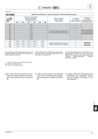
ACCESSORIES
• output shafts
•Torque arm
ZUBEHOR
• Abtriebswellen
• Drehmomentstütze
ACCESSORI
• alberi lenti
• braccio di reazione
FURTHER SPECIFICATION:
• terminal board box position if different from
standard (1)
WEITERE SPEZIFIKATIONEN:
• Stellung des Klemmenkastens des Motors,
falls diese von der Standard- Ausführung
abweicht (1)
ALTRE SPECIFICHE:
• posizione della morsettiera del motore se
diversa da quella standard (1)
1.2 Designation1.2 Designazione 1.2 Bezeichnung
WMI
FA-FB-FC
WMI
-
Senso di rotazione standard
Standard direction of rotation
Drehrichtung Standard
4.
CT16IGBD2.2
I4
1.4 Lubrication1.4 Lubrificazione1.4 Schmierung
OIL
Lubrificazione riduttori
Gearboxes lubrication
Schmierung Getriebes
WI - WMI
Mounting positions WI-WMIPosizioni di montaggio WI-WMI Montagepositionen WI-WMI
Z4
M
1
M4 M5
General information
The use of synthetic oil is recommended.
(see details in Chapter A, paragraph 1.6
and 1.2). Tab. 2.2.1 shows the quantities of
oil required for correct worm gearbox
performance.
Ordering phase requirements and state
of supply
Worm gearboxes sizes 40, 50, 63, 75, and
85 come supplied with ISO 320 viscosity
synthetic oil.
It is not necessary to specify mounting
positions with these worm gearboxes.
Size 110, 130, 150 worm gearboxes require
oil lubrication but are supplied without
lubricant that can be requested separately.
It is necessary to specify the mounting
position for these worm gearboxes.
Allgemeines
Der Einsatz von synthetischem Öl wird
empfohlen. (Siehe diesbezüglich die
Hinweise im Kapitel A, abschnitt 1.6 und
1.2.
In der Tabelle Tab. 2.2.1 werden die
erforderlichen Ölfüllmengen für einen störung-
sfreien Betrieb der Getriebe aufgeführt.
Vorgaben für die bestellung und den
lieferzustand
Die Getriebe in den Baugrößen werden
komplett mit Synthetiköl mit einer Viskosität
ISO 320 geliefert. Für diese Getriebe
muss die Einbaulage nicht angegeben
werden.
Die Getriebe in den Baugrößen 110, 130,
15080 sind bei der Lieferung für die
Ölschmierung vorbereitet, enthalten jedoch
kein Schmiermittel. Dieses kann auf
Anfrage geliefert werden. Für diese
Getriebe muss die Einbaulage verbindlich
angegeben werden.
Generalità
Si consiglia l'uso di oli a base sintetica.
Vedere a tale proposito le indicazioni
riportate nel capitolo A, paragrafo1.6 e 1.2..
Nella tab. 2.2.1 sono riportati i quantitativi di
olio necessari per il corretto funzionamento
dei riduttori.
Prescrizioni in fase di ordine e stato di
fornitura
I riduttori sono forniti completi di olio
sintetico di viscosità ISO 320.
Per questi riduttori non è necessario
specificare la posizione di montaggio.
I riduttori delle grandezze 110, 130, 150
sono forniti predisposti per lubrificazione ad
olio ma privi di lubrificante il quale potrà
essere fornito a richiesta. Per questi
riduttori è necessario specificare la
posizione di montaggio.
M1
WI - WMI
1
1
1
1
1
1
1
M3
M2 M5
M6 M4
5.
CT16IGBD2.2
I5
I
Tab. 2.2.1
WI-WMI Quantitàdi lubrificante / Lubricant Quantity / Schmiermittelmenge (kg)
Posizioni di montaggio
Mounting Positions
Montagepositionen
Stato di fornitura
State of supply
Lieferzustand
n°. tappi olio
No. of plugs
Anzahl Schrauben
Posizione di
montaggio
Mounting position
MontagepositionM1 M2 M3 M4 M5 M6
25 0.02
Riduttori forniti completi di lubrificante sintetico
Gearboxes supplied with synthetic oil
Getriebe werden mit synthetischem Öl geliefert
1
Non é necessaria
It is not necessary
Nicht Erforderlich
30 0.04 1
40 0.08 1
50 0.150 1
63 0.300 1
75 0.550 1
90 1.000 1
110 3.000 2.200 3.000 2.200 2.500
Riduttori predisposti per lubrificazione ad olio
Gearboxes supplied ready for oil lubrication
Getriebe sind für Ölschmierung vorgerüstet
3
Necessaria
Necessary
Erforderlich
130 4.500 3.300 4.500 3.300 3.500 3
150 7.000 5.100 7.000 5.100 5.400 3
A) Hinweis: Sollte in der Auftragsphase die
Einbaulage nicht angegeben werden,
wird das Getriebe mit Stopfen für die
Einbaulage M1.
B) Der Entlüftungsstopfen ist lediglich bei
den Getrieben vorhanden, die über mehr
als einen Ölfüllstopfen verfügen.
C) In den Getrieben in dem man die
Montage Position angeben soll, findet
man die angefragte Position auf dem
Typenschild des Getriebes.
A) If the mounting position is not specified
in the order, the worm gearbox supplied
will have plugs pre-arranged for position
M1.
B) A breather plug is supplied only with
worm gearboxes that have more than
one oil plug.
C) The gearboxes that need a specific
assembling position have the indication
of it on the label of the gearbox.
A) Se in fase d’ordine la posizione di mon-
taggio è omessa, il riduttore verrà fornito
con i tappi predisposti per la posizione
M1.
B) Il tappo di sfiato è allegato solo nei
riduttori che hanno più di un tappo
olio.
C) Nei riduttori dove è necessario
specificare la posizione di
montaggio, la posizione richiesta è
indicata nella targhetta del riduttore.
Carico / Breather plug / Nachfüllen - Entlüftung
Livello / Level plug / Pegel
Scarico / Drain plug / Auslauf
Le quantità di olio sono approssimative; per una
corretta lubrificazione occorre fare riferimento al
livello segnato sul riduttore.
Oil quantities listed in the table are approximate;
to ensure correct lubrication, please refer to the
level mark on the gear unit.
Bei den Ölmengenangaben handelt es sich um
approximative Werte; für den Erhalt einer
korrekten Schmierung muss Bezug auf den am
Getriebe gekennzeichneten Füllstand
genommen werden.
6.
CT16IGBD2.2
I6
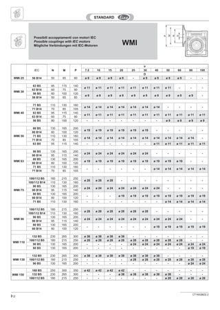
1.5 Axial andoverhung loads1.5 Carichi radiali e assiali 1.5 Radiale und Axiale
Belastungen
Il carico radiale sull’albero si calcola con la seguente formula:
Fre (N)
Carico radiale risultante
M (Nm)
Momento torcente sull’albero
D (mm)
Diametro dell’elemento di trasmissione montato sull’albero
Fr (N)
Valore di carico radiale massimo ammesso (ved. tabelle relative)
fz = 1,1 pignone dentato
1,4 ruota per catena
1,7 puleggia a gola
2,5 puleggia piana
Quando il carico radiale risultante non è applicato sulla mezzeria
dell’albero occorre calcolare quello effettivo con la seguente formula:
a , b , x = valori riportati nelle tabelle
The radial load on the shaft is calculated with the following formula:
Fre (N)
Resulting radial load
M (Nm)
Torque on the shaft
D (mm)
Diameter of the transmission member mounted on the shaft
Fr (N)
Value of the maximum admitted radial load (see relative tables)
fz = 1,1 gear pinion
1,4 chain wheel
1,7 v-pulley
2,5 flat pulley
When the resulting radial load is not applied on the centre line of the
shaft it is necessary to calculate the effective load with the following
formula:
a , b , x = values given in the tables
Die Querbelastung (Querkraft) auf der Welle wird durch
nachstehende Formel berechnet:
Fre (N)
resultierende Querkraft
M (Nm)
Wellendrehmoment
D (mm)
Durchmesser des an der Welle montierten Antriebselements
Fr (N)
max. zul. Querkraft (siehe entspr. Tafel)
fz = 1,1 Zahnrad
1,4 Rad für Kette
1,7 Flanschscheibe
2,5 Flachriemenscheibe
Wenn die Querkraft nicht auf die Mitte der Welle bezogen ist, ist die
effektive Kraft durch nachstehende Formel zu berechnen:
a , b , x: siehe Tafeln
OUTPUT SHAFTSALBERI IN USCITA ABTRIEBSWELLEN
Frx
Fr
L/2
L
Fa
WI
WMI
Fr2 (N)
25 30 40 50 63 75 90 110 130 150
a 50 65 84 101 120 131 162 176 188 215
b 38 50 64 76 95 101 122 136 148 174
Fr2 max 1350 1830 3490 4840 6270 7380 8180 12000 13500 18000
INPUT SHAFTSALBERI IN ENTRATA ANTRIEBSWELLEN
X
Frx
Fr
L/2
L
WI
Fr1 (N)
30 40 50 63 75 90 110 130 150
a 86 106 129 159 192 227 266 314 350
b 76 94.5 114 139 167 202 236 274 310
Fr1 max 210 350 490 700 980 1270 1700 2100 2800
CT16IGBD2.2
I11
I
WI 130 48.0
ir
n1= 2800 min-1
n1 = 1400 min-1
n1 = 900 min-1
n1 = 500 min-1
IECn2 T2M P n2 T2M P n2 T2M P n2 T2M P
min-1
Nm kW min-1
Nm kW min-1
Nm kW min-1
Nm kW
7.5 373.3 514 22.1 186.7 741 16.1 120 871 12.3 66.7 1071 8.6
90
100-112-132
10 280 574 18.7 140 820 13.5 90 951 10.3 50 1153 7.1
15 186.7 669 14.7 93.3 917 10.3 60 1055 7.8 33.3 1293 5.5
20 140 660 11 70 905 7.8 45 1022 5.8 25 1222 4.0
25 112 660 9.0 56 931 6.5 36 1031 4.8 20 1192 3.2
30 93.3 774 9.0 46.7 1047 6.4 30 1152 4.7 16.7 1378 3.3
40 70 727 6.5 35 1043 4.9 22.5 1099 3.5 12.5 1284 2.4
50 56 696 5.1 28 972 3.8 18 1017 2.7 10 1216 1.9
60 46.7 638 4.0 23.3 928 3.1 15 923 2.1 8.3 1105 1.5
80 35 606 3.0 17.5 853 2.3 11.3 852 1.6 6.3 967 1.1
100 28 525 2.2 14 742 1.7 9 751 1.2 5.0 877 0.85
1.6 WI Gearboxes performances 1.6 Leistungen der WI-Getriebe1.6 Prestazioni riduttori WI
NOTE. Please pay attention to the frame
around the input power value: for this
gearboxes it’s important to check the
thermal capacity (comp. chapter 1.7-A). For
details please contact our technical
HINWEIS. Sind in den Tabellen
Nennleistungen eingerahmt, so ist die
thermische Leistungsgrenze der Getriebe
zu beachten (s. S. 1.7-A).
Für weitere Informationen wenden Sie sich
N.B. Per i riduttori evidenziati dal doppio
bordo nella colonna delle potenze è
necessario verificare lo scambio termico
del riduttore (come nel par. 1.7-A). Per
maggiori informazioni contattare l’ufficio
Listed weights are for reference only and can
vary according to the gearbox version.
Die angegebenen Gewichte sind Richtwerte und
können je nach Getriebeversion etwas variieren.
I pesi riportati sono indicativi e possono variare
in funzione della versione del riduttore.
ATTENZIONE! WARNING! ACHTUNG!
Per situazioni con velocità di ingresso
particolari attenersi alla tabella sotto
riportata che evidenzia situazioni critiche
per ogni riduttore (Vedere paragrafo
If in presence of non standard input speed
please attain to the chart below considering
extreme usage conditions for each
gearbox (Look at chapter 1.2-A).
Mit unstandardisierte
Antriebsgeschwindigkeit bitte auf folgende
Liste Bezug nehmen in Betrachtung der
schwierigen Arbeitsbedingungen fuer jede
UI - RI - WI
25 28 30 40 50 63 70 75 85 90 110 130 150 180
1500 < n1 < 3000 OK OK OK OK OK Contattare il ns. servizio tecnico
Contact our technical dept
Wenden Sie sich an unseren technischen Servicen1 > 3000
WI 150 84.0
ir
n1 = 2800 min-1
n1 = 1400 min-1
n1 = 900 min-1
n1 = 500 min-1
IECn2 T2M P n2 T2M P n2 T2M P n2 T2M P
min-1
Nm kW min-1
Nm kW min-1
Nm kW min-1
Nm kW
7.5
-
186.7 1200 25.5
-
-
100-112
132-160
10 140 1240 19.5
15 93.3 1250 13.5
20 70 1300 10.5
25 56 1200 8.8
30 46.7 1200 7.4
40 35 1550 7.4
50 28 1400 5.5
60 23.3 1260 4.4
80 17.5 1150 3.2
100 14 1000 2.4
CT16IGBD2.2
I14
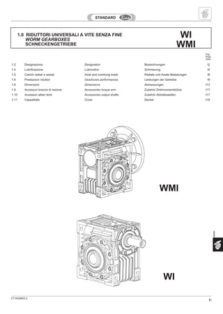
1.8 Dimensions1.8 Dimensioni1.8 Abmessungen
Dimensioni riduttori
Gearboxes dimensions
Abmessungen Getriebes
WI - WMI
30-40-50-63-75-110-130
B
a
M0
S
L
M L
d
m m
d
M0L
I
d m
m
Vp
Fp
w
Rp
f
E2
E1
hH
E1
b
B
tyY
Dy
b2
by
D
CC
G
Z
U
V
W1
FQ
F
R
Gp
Pp Pp
C C
t2
P
b1
t1
b1
t1
A
S1
KN
FA
FB
FC
I
15.
I15
I
WI
WMI
A a Bb C D
H7
d
j6
E1 E2 f h H I L M M0 m N S S1
30 80 54 56 44 31,5 14 9 44 27 6,5 57 40 30 20 51 45 - 40 5,5 97
40 100 70 71 60 39 18 11 55 35 6,5 71,5 50 40 23 60 53 - 50 6,5 121.5
50 120 80 85 70 46 25 14 64 40 8,5 84 60 50 30 74 64 M6 60 7 144
63 144 100 103 85 56 25 19 80 50 8,5 102 72 63 40 90 75 M6 72 8 174
75 172 120 112 90 60 28 24 93 60 11 119 86 75 50 105 90 M8 86 10 205
90 208 140 130 100 70 35 24 102 70 13 135 103 90 50 125 108 M8 103 11 238
110 252.5 170 144 115 77,5 42 28 125 85 14 167,5 127,50 110 60 142 135 M10 127,50 14 295
130 292.5 200 155 120 85 45 30 140 100 16 187,5 147,50 130 80 162 155 M10 147,50 15 335
150 340 240 185 145 100 50 35 180 120 18 230 170,00 150 80 192 175 M12 170,00 18 400
WI
WMI
Fp Gp
(h8)
Pp Rp Up Vp W
b2 t2 b1 t1
30 75 55 29 65 M6X11(n,4) 0 5 16,3 3 10,2
40 87 60 36,5 75 M6X8(n,4) 45 6(6) 20.8(21.8) 4 12,5
50 100 70 43,5 85 M8X10(n,4) 45 8(8) 28.3(27.3) 5 16,0
63 110 80 53 95 M8X14(n,8) 45 8(8) 28.3(31.3) 6 21,5
75 140 95 57 115 M8X14(n,8) 45 8(10) 31.3(38.3) 8 27,0
90 160 110 67 130 M10X18(n,8) 45 10(10) 38.3(41.3) 8 27,0
110 200 130 74 165 M10X18(n,8) 45 12 45,3 8 31,0
130 250 180 81 215 M12X21(n,8) 45 14 48,8 8 33,0
150 250 180 96 215 M12X21(n,8) 45 14 53,8 10 38,0
WI
WMI
F Fq
G
(H8)
P R U V Z W1
WI
WMI
F Fq G(F8) P R U V Z W1
30 FA 80 70 50 54,5 68 4 6.5(n,4) 6 45
40
FA 110 95 60 67 87 4 9(n,4) 7 45
FC 140 - 95 76,5 115 5 9.5(n,4) 9 45
FB 110 95 60 97 87 4 9(n,4) 7 45
50
FA 125 110 70 90 90 5 11(n,4) 9 45
FC 160 - 110 87,5 130 5 9.5(n,4) 10 45
FB 125 110 70 120 90 5 11(n,4) 9 45
63
FA 180 142 115 82 150 6 11(n,4) 10 45
FC 200 - 130 99 165 5 11(n,4) 11 45
FB 180 142 115 112 150 6 11(n,4) 10 45
75 FA 200 170 130 111 165 6 14(n,4) 13 45
90 FA 210 200 152 111 175 6 14(n,4) 13 45
110 FA 280 260 170 131 230 6 14(n,4) 15 45
130 FA 320 290 180 140 256 6 16(n,4) 15 22.50
150 FA 320 290 180 155 255 6 16(n,4) 15 22.50
1.8 Dimensions1.8 Dimensioni 1.8 Abmessungen
WM
I
30 40 50 63 75 90 110 130 150
Y K Y K Y K Y K Y K Y K Y K Y K Y K
B5
120 55 120 70
140 55 140 70 140 80
160 70 160 80 160 95 160 112,5
200 80 200 95 200 112,5 200 129,5 200 160 200 180
250 112,5 250 129,5 250 160 250 180 250 210
300 160 300 180 300 210
350 210
B14
80 55
90 55 90 70
105 70 105 80 105 95
120 80 120 95 120 112,5 120 129,5
140 95 140 112,5 140 129,5
160 112,5 160 129,5
CT16IGBD2.2
16.
CT16IGBD2.2
I16
WMI IEC
B5 5663 71 80 90 100 112 132 160 180 200
Y 120 140 160 200 200 250 250 300 350 350 400
Dy 9 11 14 19 24 28 28 38 42 48 55
by 3 4 5 6 8 8 8 10 12 14 16
ty 10.4 12.8 16.3 21.8 27.3 31.3 31.3 41.3* 45.3 51.8 59.3
* WMI 130 ty=40.3 (IEC 132)
1.8 Dimensions1.8 Dimensioni 1.8 Abmessungen
PAM B5 -DimensionsPAM B5 - Dimensioni PAM B5 - Abmessungen
ty
by
Dy
Y
PAM B14 -DimensionsPAM B14 - Dimensioni PAM B14 - Abmessungen
WMI IEC
B5 56 63 71 80 90 100 112 132
Y 80 90 105 120 140 160 160 200
Dy 9 11 14 19 24 28 28 38
by 3 4 5 6 8 8 8 10
ty 10.4 12.8 16.3 21.8 27.3 31.3 31.3 41.3*
* WMI 130 ty=40.3 (IEC 132)
ty
by
Dy
Y

![I2
Grandezza
Size
Größe
Versione
Version
Ausführung
ir IEC
Tipo
Type
Typ
Grandezza
Size
Gröe
Lunghezza
Lenght
Länge
[*1] [*2] [*3]
25
30
40
50
63
75
90
110
130
150
-
FA
FB
FC
vedi
tabelle
see tables
siehe
Tabellen
63 (B5)
—
—
(standard)
SIN
WMI
63 (B14)
....
T 56 A
TA .... ....
-
B
.... 315 ML
WI
WMI 40 1/20 PAM 63
(B5)
WMI 40 1/20 T 56 A 4 B5
WI 40 1/20
1.2 Designation1.2 Designazione 1.2 Bezeichnung
Designazione Motori
Designation Motors
Bezeichnung Motoren
CT18IGBD1
• [*1] Bisporgenza Vite:
Nessuna indicazione = vite senza
bisporgenza;
B = vite con bisporgenza.
• [*2] Diametro albero:
Nessuna indicazione = diametro foro
standard;
diametro foro opzionale = (vedi
tabella).
• [*8] Mounting position output side:
No indication (standard) = output flange
on right side (like indicated in the figures);
SIN = output flange on left side (flanges
on the opposite side like indicated in
figures).
• [*3] Lato flangia uscita:
Nessuna indicazione = flangia uscita con
montaggio destro (flange dal lato come
indicato nelle figure del catalogo);
SIN = flange uscita con montaggio
sinistro (flange dal lato opposto alle
figure indicate a catalogo).
• [*8] Montageseite Abtriebsflansch:
Keine Angabe (Standard) = Abtriebs-
flansch rechts (wie in den Abbildungen
dargestellt)
SIN = Abtriebsflansch links (gegenüber
der Position in den Katalogabbildungen).
• [*1] Doppelseitige Schneckenwelle
Keine Angabe = Schnecken ohne
doppeltes Wellenende
B = Schnecke mit doppeltem
Wellenende
• [*2] Wellendurchmesser:
Keine Angabe =
Standard-Bohrungsdurchmesser
Optionaler Bohrungsdurchmesser =
(siehe Tabelle).
• [*1] Double Extended Input Shaft
No indications = input shaft without
double extension;
B = double extended input shaft.
• [*2] Shaft Diameter:
No indications = standard hole diameter;
optional hole diameter = (see table).
Grandezza - Size - Größe
WI - WMI 25 30 40 50 63 75 90 110 130 150
D H7 Standard 11 14 18 25 25 28 35 42 45 50
CT16IGBD2.2](https://image.slidesharecdn.com/katalog-wi-wmi-170824052227/85/wi-wmi-STM-2-320.jpg)