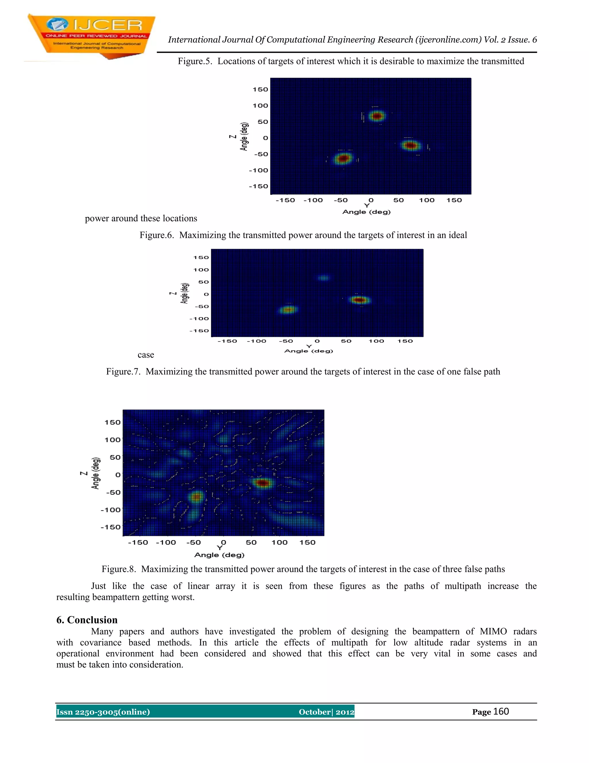
This document discusses the design of low-altitude multiple input multiple output (MIMO) radar beam patterns, particularly focusing on the effects of multipath signals in operational environments. It highlights various radar waveform design methods, with emphasis on covariance-based approaches, and provides numerical examples to illustrate the impact of multipath on beampattern performance. The study concludes that multipath effects can significantly affect radar performance and must be accounted for in design considerations.
![International Journal Of Computational Engineering Research (ijceronline.com) Vol. 2 Issue. 6
Analyzing Of Low Altitude Mimo Radarbeampattern Design
1,2
Amirsadegh Roshanzamir1,Mohammad hasan Bastani2
Department of Electrical Engineering Sharif University of TechnologyTehran, Islamic Republic of Iran
Abstract:
A multiple input multiple output (MIMO) radar is an emerging field which has attracted many
researchers recently. In this type of radar, unlike an standard phased array radar, one can choose transmitted
probing signals freely to maximize the power around the locations of the targets of interest, or more generally to
approximate a given transmit beam-pattern, or to minimize the cross-correlation of the signals reflected back to
the radar by the targets of interest. These signals can be correlated to each other or non-correlated. Many papers
have investigated beampattern design and waveforming in MIMO radars. One of the most famous approaches
for beampattern design is named covariance based method which design cross-correlation matrix of transmitted
signals instead of the own signalsdirectly. Many papers have investigated the problem of MIMO radar
beampattern design in an ideal operational environment. But one of the important operational situations which
causes faults and errors to the radar systems is low altitude track, detection and etc. It is because of in low
altitude operations beside of the desire reflected signals multipath signals will be received too. In this article it
is desirable to study the effect of multipath of a MIMO radar system which is employing cross-correlation
matrix of transmitted signals to designing the transmitted beampattern. MATLAB software is being employed
for simulations.
Keywords:Multipath, MIMO radar, low altitude; beampatterndesign, covariance based method.
1. Introduction
Multiple input multiple output (MIMO) radar is an emerging radar field which has attracted many
researchers from all over the world recently. In this type of radar, unlike an standard phased array radar, one can
choose transmitted probing signals freely to maximize the power around the locations of the targets of interest,
or more generally to approximate a given transmit beam-pattern, or to minimize the cross-correlation of the
signals reflected back to the radar by the targets of interest [1,2]. These signals can be correlated to each other
or non-correlated. This feature provides extra degrees of freedom in the design of radar system. Generally
MIMO radar systems can be classified into two main categories:
1. MIMO radars with widely separated antennas [3]
2. MIMO radars with colocated antennas [4]In the case of widely separated antennas, the transmitting antennas
are far from each other such that each views a different aspect of a target of interest. In this type of MIMO
radars, the concept of MIMO can be used to increase the spatial diversity of the radar system [5,6,7,8]. this
spatial diversity which has been achieve from RCS diversity gain, can improve the performance of detection
[7], finding slow moving targets [5] and angle estimation [8]. Useful references about MIMO radar with
widely separated antennas can be found in [3].In the case of MIMO radar with colocated antennas, the
transmitting antennas are close to each other such that the aspects of a target of interest observed by antenna
elements, are identical. In this type of MIMO radars, the concept of MIMO can be used to increase the
spatial resolution. Many papers have demonstrated the advantages of this type of MIMO radars, including
high interference rejection capability [9,10], improved parameter identifiability [11], and enhanced
flexibility for transmit beampattern design [12,13]. useful references about MIMO radars with colocated
antennas can be found in [4].Generally MIMO radar waveform design methods can be classified into three
main categories [12] - [23]:
1. Covariance matrix based design methods [12] – [16]
2. Radar ambiguity function based design methods [17] – [20]
3. Extended targets based design methods [21] – [23]
Issn 2250-3005(online) October| 2012 Page 154](https://image.slidesharecdn.com/ad02601540161-121102023509-phpapp02/75/International-Journal-of-Computational-Engineering-Research-IJCER-1-2048.jpg)
![International Journal Of Computational Engineering Research (ijceronline.com) Vol. 2 Issue. 6
In the covariance matrix based design methods, the cross correlation matrix of transmitted signals is
taken into consideration instead of entire waveform. Then these types of waveform design methods affect only
the spatial domain. In references [12,14] the cross correlation matrix of transmitted signals is design such that
the power can be transmitted to a desire range of angles. In [13] the cross correlation matrix of transmitted
signals is design such that one can control the spatial power.
In addition in [13] the cross correlation between the transmitted signals at a number of given target
locations is minimized which can improved the spatial resolution in the radar receiver. In [15] the authors have
optimized the covariances between waveforms based on the Cramer – Rao bound matrix. And finally in [16],
given the optimize covariance matrix, the corresponding signal waveforms are designed to further achieve low
peak to average power ratio (PAR) and higher range resolution.The radar ambiguity based design methods
optimize the entire signal instead of matrix of cross correlation of the signals. Then these design methods
involve not only the spatial domain but also the range domain. Actually in these design methods it is desirable
to find a set of signals which satisfied a desire radar ambiguity function. Of course these design methods are
more complicated than the covariance design methods. Angle, Doppler and range resolution of a radar system
can be characterized by the MIMO radar ambiguity function [24] – [26]. In [18] – [20] the authors goal is to
sharpen the radar ambiguity function. For achieving this goal the authors have minimized the sidelobe of the
autocorrelation and the cross correlation between the signals. In [17] the signals are directly optimized so that a
sharper radar ambiguity function can be obtained. Then the spatial and range resolution of point targets can be
improved.In the extended target based design methods also, the entire signals is considered as in the radar
ambiguity function design based methods, however, unlike the radar ambiguity function design based methods
which considered only the resolutions of point targets, these methods considered the detection and estimation of
extended targets. These methods require some prior information about the target or clutter impulse response.
The extended target based design methods have been studied in [17] – [20].
Many papers have investigated beampattern design and waveforming in MIMO radars. One of the
most famous approaches for beampattern design (as mentioned before) is named covariance based method
which design cross-correlation matrix of transmitted signals instead of the signals. On the other hand, many
papers have investigated beamforming of an standard phased array radar in different ways. In this paper it is
desirable to design beampattern of a phased array radar by means of the MIMO radar covariance based
beampattern design method, as a special case of general MIMO radar.
The present study has six sections as follow:
Section 1 presents a brief introduction of MIMO radars. In section 2 the covariance based MIMO radar
beamforming is reviewed. Utilization a model of maximizing the transmitted power around the locations of the
targets of interest is discussed in section 3. Utilization a model of beampattern design in presence of multipath
is discussed in section 4. Numerical examples are provided in section 5. Section 6 is focused on conclusion and
references are presented at the end of the paper.
2. Covariance Based Method For MIMO Radar Beampattern Design
Assume that we have a collection of N transmitter antenna which are located at known coordinates
in some spherical coordinate along the z-axis as shown in Figure. 1. In the
presented study and in all of the examples and formulas of current paper, it is assume that these transmitter
antennas are along the z-axis. It is assume that each transmitter antenna is driven by a specific signal on the
carrier frequency of or with wavelength of and complex envelope of . At a specific point in
space with distance of and direction of from the transmitter antenna, each radiated signal gives
rise to a "signal" the far field at radius r, with complex envelope given by
Where, in this equation, k is a unit vector in the direction.
Issn 2250-3005(online) October| 2012 Page 155](https://image.slidesharecdn.com/ad02601540161-121102023509-phpapp02/75/International-Journal-of-Computational-Engineering-Research-IJCER-2-2048.jpg)
![International Journal Of Computational Engineering Research (ijceronline.com) Vol. 2 Issue. 6
Figure. 1. T/R modules and spherical coordinate system
At the far field, these signals add linearly and the radiated powers add linearly as well. At this point
assume that the i-th element location is on the z-axis at coordinate . The signal at position resulting
from all of the transmitted signals at far field will be:
The power density of the entire signals then given by
And it is known that the complex signal cross-correlation is defined by
With defining the direction vector as below
The normalized power density of signals, in (W/ster), would be:
Recognizing that (6) is quadratic form in the Hermitian matrix R which is the cross-correlation matrix of
signals, this can be written compactly as
This normalized power density is exactly the beampattern which is desirable to find [3]. In the following
some examples of beampatterns produce from such a cross-correlation matrix has been shown. Figure. 2 shows
Issn 2250-3005(online) October| 2012 Page 156](https://image.slidesharecdn.com/ad02601540161-121102023509-phpapp02/75/International-Journal-of-Computational-Engineering-Research-IJCER-3-2048.jpg)
![International Journal Of Computational Engineering Research (ijceronline.com) Vol. 2 Issue. 6
the beampattern produced by signal cross-correlation matrix of (8), (9) and (10)
respectively. It is noticeable that these figures are beam-patterns of 10-element uniform linear array (ULA) with
half-wavelength spacing.
Beampattern of (8)
Beampattern of (9)
Beampattern of (10)
-2 -1 0 1 2
Anlge (rad)
Figure. 2. Beampattern respect to (7). The blue one is corresponds to cross-correlation matrix of (8), The black one
iscorresponds to cross-correlation matrix of (9) and the red one is corresponds to cross-correlation matrix of (10)
In general case the elements of the signal cross-correlation matrix are complex values except the
diagonal elements that are real. This general case is related to MIMO radars but in the case of phased array
radar, all the transmitter signals are correlated with each other and then absolute value of all the elements in ,
are equal to 1(blue one at Figure. 2).
3. Maximizing the Transmitter Power Around The Locations Of Targets Of Interest
In [13] the authors have introduced a cost function to maximize the transmitter power around some interest
location for MIMO radars which is written bellow:
Where in these equations is the cross correlation matrix of transmitted signals and is an estimation
of , the location of the targets, which is shown below:
Issn 2250-3005(online) October| 2012 Page 157](https://image.slidesharecdn.com/ad02601540161-121102023509-phpapp02/75/International-Journal-of-Computational-Engineering-Research-IJCER-4-2048.jpg)
![International Journal Of Computational Engineering Research (ijceronline.com) Vol. 2 Issue. 6
Where in general case it is assumed that there is total number of targets
with the locations which is denoted by .In [13] the authors have solved the above problem in a general case of
MIMO which its transmitted signals can be arbitrary chosen. This answer would be of the form bellow:
Where in this equation is eigenvector related to maximum eigenvalue of . In this article it is
desirable to investigate the effect of multipath on this approach.
4. Beampattern Signal model in presence of multipath
Form (7) it is understood that if multipath exists, the equation of (7) will be rewritten as bellow:
Where in this equation is the number of multipath which the transmitted signals will be arrived to
the receiver by them and denotes the corresponding cross-correlation matrix of transmitted signals throw
each paths. It is known that for it will show the cross correlation matrix of transmitted signals throw the
main or line of sight path.For each element of can be modeled by complex number of amplitude with
normal distribution of zero mean and some variancesrespect to the operational environment, and the phase with
uniform distribution between and .In the section of numerical examples the effect of multipath is compared
to the ideal situation in the sense of (13).
5. Numerical examples
In this section it is desirable to examine the effect of multipath with some numerical examples.
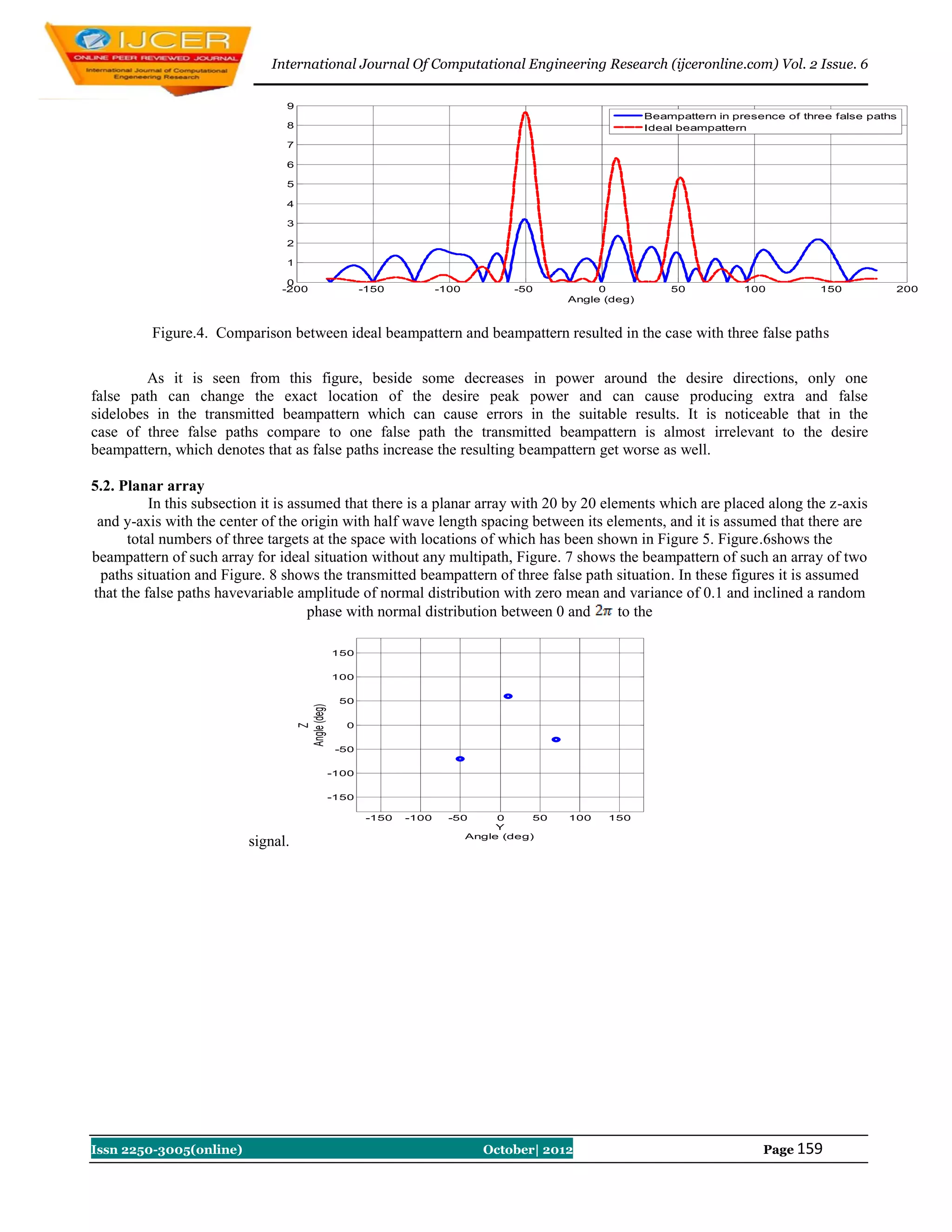
5.1. Linear array
In this subsection it is assumed that there is a linear array with 20 elements which are placed along the
z-axis with the center of the origin with half wave length spacing between its elements, and it is assumed that
there are total numbers of three targets at the space with locations of [-50 10 60] degrees. Figure 3 shows the
beampattern of such array for ideal and two paths situation. In this figure it is assumed that the false path has a
variable amplitude of normal distribution with zero mean and variance of 0.1 and inclined a random phase with
normal distribution between 0 and to the signal.
9
Beampattern in presence of one false path
8 Ideal beampattern
7
6
5
4
3
2
1
0
-200 -150 -100 -50 0 50 100 150 200
Angle (deg)
Figure.3. Comparison between ideal beampattern and beampattern resulted in the case with one false path
As it is seen from this figure, beside some decreases in power around the desire directions,only one
false path can change the exact location of the desire peak power and can cause producing extra and false
sidelobes in the transmitted beampattern which can cause errors in the suitable results.Figure 4 shows the
beampattern of an array with the above characteristics for ideal and four paths situation. In this figure it is
assumed that the false pathshave variable amplitudes of normal distribution with zero mean and variance of 0.1
and inclined a random phase with normal distribution between 0 and to the signal.
Issn 2250-3005(online) October| 2012 Page 158](https://image.slidesharecdn.com/ad02601540161-121102023509-phpapp02/75/International-Journal-of-Computational-Engineering-Research-IJCER-5-2048.jpg)
![International Journal Of Computational Engineering Research (ijceronline.com) Vol. 2 Issue. 6
References
[1] D. J. Rabideau and P. Parker, “Ubiquitous MIMO multifunction digital array radar,” in Proc. 37th IEEE
Asilomar Conf. Signals, Syst., Comput., Nov. 003, vol. 1, pp. 1057–1064.
[2] D. W. Bliss and K. W. Forsythe, “Multiple-input multiple-output (MIMO) radar and imaging: Degrees of
freedom and resolution,” in Proc. 37th IEEE Asilomar Conf. Signals, Syst., Comput., Nov. 2003, vol. 1,
pp. 54–59.
[3] A. M. Haimovich, R. S. Blum, and L. J. Cimini, “MIMO radar with widely separated antennas,” IEEE
Signal Process. Mag., vol. 25, no. 1, pp. 116–129, Jan. 2008.
[4] J. Li and P. Stoica, “MIMO radar with colocated antennas,” IEEE Signal Process. Mag., vol. 24, no. 5,
Sep. 2007.
[5] E. Fishler, A.M. Haimovich, R. S. Blum, D. Chizhik, L. J. Cimini, and R. A. Valenzuela, “MIMO radar:
An idea whose time has come,” in Proc. IEEE Radar Conf., Apr. 2004, pp. 71–78.
[6] E. Fishler, A.M. Haimovich, R. S. Blum, L. J. Cimini, D. Chizhik, and R. A. Valenzuela, “Performance of
MIMO radar systems: Advantages of angular diversity,” in Proc. 38th IEEE Asilomar Conf. Signals,
Syst., Comput., Nov. 2004, vol. 1, pp. 305–309.
[7] E. Fishler, A.M. Haimovich, R. S. Blum, L. J. Cimini, D. Chizhik, and R. A. Valenzuela, “Spactial
diversity in radars-models and detection performance,” IEEE Trans. Signal Process., vol. 54, no. 3, pp.
823–837, Mar. 2006.
[8] C. Duofang, C. Baixiao, and Q. Guodong, “Angle estimation using esprit in MIMO radar,” Electron.Lett.,
vol. 44, no. 12, pp. 770–771, Jun. 2008.
[9] C. Y. Chen and P. P. Vaidyanathan, “MIMO radar space-time adaptive processing using prolate
spheroidal wave functions,” IEEE Trans. Signal Process., vol. 56, no. 2, Feb. 2008.
[10] V. F. Mecca, D. Ramakrishnan, and J. L. Krolik, “MIMO radar space-time adaptive processing for
multipath clutter mitigation,” in IEEE Workshop on Sens. Array and Multichannel Signal Process., Jul.
2006, pp. 249–253.
[11] J. Li, P. Stoica, L. Xu, and W. Roberts, “On parameter identifiability of MIMO radar,” IEEE Signal
Process. Lett., vol. 14, Dec. 2007.
[12] D. R. Fuhrmann and G. S. Antonio, “Transmit beamforming for MIMO radar systems using partial signal
correlation,” in Proc. 38th IEEE Asilomar Conf. Signals, Syst., Comput., Nov. 2004, pp. 295–299.
[13] P. Stoica, J. Li, and Y. Xie, “On probing signal design for MIMO radar,” IEEE Trans. Signal Process.,
vol. 55, no. 8, pp. 4151–4161, Aug. 2007.
[14] D. R. Fuhrmann and G. S. Antonio, “Transmit beamforming for MIMO radar systems using signal cross-
correlation,” IEEE Trans. Aerosp. Electron. Syst., vol. 44, pp. 171–186, Jan. 2008.
[15] J. Li, L. Xu, P. Stoica, K. W. Forsythe, and D. Bliss, “Range compression and waveform optimization for
MIMO radar: A Cramér–Rao bound based study,” IEEE Trans. Signal Process., vol. 56, no. 1, pp. 218–
232, Jan. 2008.
[16] P. Stoica, J. Li, and X. Zhu, “Waveform synthesis for diversity-based transmit beampattern design,” IEEE
Trans. Signal Process., Jun. 2008.
[17] C. Y. Chen and P. P. Vaidyanathan, “MIMO radar ambiguity properties and optimization using
frequency-hopping waveforms,” IEEE Trans. Signal Process., Dec. 2008.
[18] J. Li, P. Stoica, and X. Zheng, “Signal synthesis and receiver design for MIMO radar imaging,” IEEE
Trans. Signal Process., Aug. 2008.
[19] B. Liu, Z. He, J. Zeng, and B. Y. Liu, “Polyphase orthogonal code design for MIMO radar systems,” in
Proc. Int. Conf. Radar, Oct. 2006,pp. 1–4.
[20] B. Liu, Z. He, and Q. He, “Optimization of orthogonal discrete frequency-coding waveform based on
modified genetic algorithm for MIMO radar,” in Proc. Int. Conf. Commun., Circuits, Syst., Jul. 2007, pp.
966–970.
[21] B. Friedlander, “Waveform design for MIMO radars,” IEEE Trans. Aerosp.Electron. Syst., vol. 43, pp.
1227–1238, Jul. 2007.
[22] Y. Yang and R. S. Blum, “MIMO radar waveform design based on mutual information and minimum
mean-square error estimation,” IEEE Trans. Aerosp.Electron. Syst., vol. 43, no. 1, pp. 330–343, Jan.
2007.
[23] Y. Yang and R. S. Blum, “Minimax robust MIMO radar waveform design,” IEEE J. Sel. Topics Signal
Process., vol. 1, no. 1, pp. 147–155, Jun. 2007.
[24] G. San Antonio, D. R. Fuhrmann, and F. C. Robey, “MIMO radar ambiguity functions,” IEEE J. Sel.
Topics in Signal Process., vol. 1, pp. 167–177, Jun. 2007.
Issn 2250-3005(online) October| 2012 Page 161](https://image.slidesharecdn.com/ad02601540161-121102023509-phpapp02/75/International-Journal-of-Computational-Engineering-Research-IJCER-8-2048.jpg)
![International Journal Of Computational Engineering Research (ijceronline.com) Vol. 2 Issue. 6
[25] Y. I. Abramovich and G. J. Frazer, “Bounds on the volume and height
distributions for the MIMO radar ambiguity function,” IEEE Signal Process. Lett., vol. 15, pp. 505–508.
[26] J. Y. Qu, J. Y. Zhang, and C. Q. Liu, “The ambiguity function ofMIMO radar,” in Proc. Int. Symp.
Microw., Antenna, Propag. EMC Technol. Wireless Commun., Aug. 2007, pp. 265–268.
Issn 2250-3005(online) October| 2012 Page 162](https://image.slidesharecdn.com/ad02601540161-121102023509-phpapp02/75/International-Journal-of-Computational-Engineering-Research-IJCER-9-2048.jpg)