
Recommended
Recommended
More Related Content
Similar to ACVG and PCM Completed Alternating C.pdf
Similar to ACVG and PCM Completed Alternating C.pdf (20)
Recently uploaded
Recently uploaded (20)
ACVG and PCM Completed Alternating C.pdf
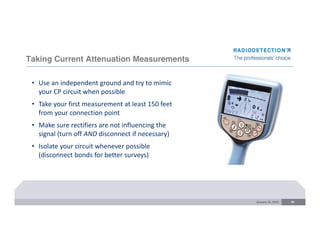
- 1. Taking Current Attenuation Measurements January 22, 2015 43 • Use an independent ground and try to mimic your CP circuit when possible • Take your first measurement at least 150 feet from your connection point • Make sure rectifiers are not influencing the signal (turn off AND disconnect if necessary) • Isolate your circuit whenever possible (disconnect bonds for better surveys)
- 2. Taking Current Attenuation Measurements January 22, 2015 44 • Take readings at equal distances and record your distances • Every 50 feet is a good standard (others can be used dependent on location) • Use it as a macro tool and depth of cover tool (use A‐frame for micro) • Look for anomalies with more than a 5% change normally • Make sure unit is upright and perpendicular to the pipe
- 3. Taking Current Attenuation Measurements January 22, 2015 45 • Stay on Peak and check peak and null readings and verify depth when readings are suspect • Take multiple readings in one location if you are suspect of the accuracy • Know what is in the area of your pipe and what it’s connected to • Use current direction to verify that signal is flowing back toward transmitter on pipe
- 4. Practical Example January 22, 2015 46 0 10 20 30 40 50 60 70 0 500 1000 1500 2000 2500 3000 3500 4000 4500 5000 4Hz (dBmA) Distance 4Hz…
- 5. January 22, 2015 47 Current Attenuation Graph 3 steps are different looking in mA but nearly identical in dB
- 6. ACVG Is Used to Pinpoint Defect Location January 22, 2015 48 Once survey is complete, use the A-Frame accessory to pinpoint defects Connect the A-Frame to the locator • Set locator to ACVG • Must use either ELCD or LFCD
- 7. Transmitter Connections January 22, 2015 49 • Rectifier •Test Station Anodes CP Rectifier AC Feed Pipeline + - ACVG Tx
- 8. ACVG - Pool of Potential January 22, 2015 50
- 9. ACVG – Current Flow January 22, 2015 51 • Current from the transmitter creates a voltage gradient around coating defects • Current density greatest at interface between the defect and the surrounding environment • Current density function of soil resistivity & Tx output Transmitt er
- 10. ACVG – Using the A Frame January 22, 2015 52 Front of receiver Directional Display GREEN RED Keep the green pin facing forward
- 11. January 22, 2015 53 Finding Coating Defects Transmitter A-Frame
- 12. January 22, 2015 54 ACVG – Receiver Readings NACE Rocky Mountain Section Short Course 2015 44 dB 47 dB 50 dB 49 dB 46 dB 43 dB • An increase in voltage gradient will cause an increase in current density near a given coating defect on the pipeline under test • Signal current and voltage effects viewed on instrument’s display • Signal current direction is displayed as an arrow • Voltage is identified as decibels (dB)
- 13. January 22, 2015 55 ACVG – Receiver Readings
- 14. January 22, 2015 56 ACVG – Receiver Readings NACE Rocky Mountain Section Short Course 2015
- 15. January 22, 2015 57 ACVG – Receiver Readings • Take 4 readings in a cross pattern ‐ two in line with the pipe and two perpendicular to the pipe • All four arrows should point to the defect • Record highest dB reading
- 16. An explanation of dBs and why we use them 58 • ACVG results are expressed in dBuV • We use the dB scale as it reduces large variances to relatable numbers • Although the dB reading, when normalized, represents a good guide of the scale of current loss due to a coating defect, there are some factors which can affect the reading, such as: • Soil resistivity • Size of the defect • Making good ground contact with the A‐Frame spikes • Therefore: magnitude of the current lost from the pipe (measured by the dB reading) depends on both the size of the defect and the conductivity of the soil surrounding the pipe. Transmitter A-Frame
- 17. Categorizing the Results* 59 Suggested category ranges – may vary by company 0 – 30dB Clear for now 30dB – 60dB Minor 60dB – 80dB Intermediate 80dB+ Major *Categories apply to normalized results @1A of 4Hz current. The formula for calculating the normalized results: Normalizing adjustment = 20*log(i/iref)
- 18. The Formula 60 This output of the formula gives you the number of dB to add or subtract from the reading, depending on whether the PCM (4Hz) current is above or below one Amp at (or just before) the defect. Normalizing adjustment = 20*log(i/iref) Example: • Observed dB reading is max 65dB right before the defect. • Measured PCM 4Hz survey current just before the defect is 500mA • The iref is 1000 mA (one Amp). In the case of 500 mA the formula is: 20 X log (500/1000) which equals -6.02 Therefore the actual dB reading when normalized is 65 + 6 = 71dB Note: If the output of the formula is negative you add the number to the ACVG reading, if it positive you subtract it. (see table on next page)
- 19. The Normalized Result 61 This formula gives you the number of dB to add or subtract from the reading, depending on whether the PCM (4Hz) current is above or below 1 Amp at (or just before) defect. Normalizing adjustment = 20*log(i/iref) 4Hz Current reading (i) Result of formula To get normalized reading 3,000mA 9.54 Subtract 10dB from ACVG reading 2,000mA 6.02 Subtract 6dB from ACVG reading 1,000mA 0.00 ACVG reading is already normalized 500mA ‐6.02 Add 6dB to ACVG reading 250mA ‐12.04 Add 12dB to ACVG reading 100mA ‐20 Add 20dB to ACVG reading 31.6mA ‐30 Add 30dB to ACVG reading 10mA ‐40 Add 40dB to ACVG reading 1mA ‐60 Add 60dB to ACVG reading
- 20. ACVG Summary January 22, 2015 62 NACE Rocky Mountain Section Short Course 2015 • Use an independent ground and try to mimic your CP circuit when possible • Take readings parallel and along the pipe. When you see an arrow reversal go perpendicular to the pipe and make sure all four arrows point to the defect • You do not have to be right on top of the pipe when surveying • On concrete and asphalt use wet sponges or rags on the probes or wet the ground around the probes. • Take readings at equal distances usually about every ten feet • Use the largest dB reading seen around the anomaly for you records • Record all faults seen with dB readings and footages or GPS coordinates. • Take a PCM current reading at the site of the defect and adjust your dB reading to normalize for one Amp of current
- 21. Summary 63 • PCMx is the new pipeline current mapping system to replace the PCM+ • Receiver • Lighter weight design based on RD8100 platform • Removable foot: RD8100PDLG with foot removed • Faster Measurements, simultaneous surveys • New transmitter Tx-25PCM • 1 Amp battery powered transmitter for extra portability
- 22. PCMx: an overview 64 Radiodetection’s new pipeline current mapping range features a lighter weight design and battery operated transmitter for greater portability and flexibility in the field. In‐built GPS on the receiver, and companion mobile application ensure field operators have the best information at their fingertips
- 23. PCMx: a complete system for pipeline surveying 65 Tx‐25 • Smaller, lighter weight, 1 Amp transmitter aimed at distribution networks • Battery powered for easy portability • 8kHz locating frequency Tx‐150 • Long range 3 Amp transmitter for transmission lines Mobile App • Improved survey experience using mobile app alongside receiver • Live charting of results allows on‐site analysis • Walk forward and walk back features makes surveying easier PC Application • Improved charting capability Not a single product but a range including : PCMx Receiver: • New lightweight design based on RD8100 • Detachable magnetometer makes receiver dual function. PCM functionality with foot on, premium RD8100 with foot off • Faster survey measurements and take 2 types of measurements simultaneously
- 24. PCMx receiver features 66 Removable magnetometer Fully featured locator with all frequencies of RD8100PDLG when foot is removed One second 4Hz measurement Faster collection of survey data Simultaneous ACVG and ACCA data capture Plus depth of cover and GPS information. Faster surveying: collect data in one pass of pipeline Mobile App Graphing in the field, walk back and walk forward features Built in GPS Automatic capture of GPS co-ordinates on survey logs eCert Confidence in the field with self- test options Li-Ion rechargeable battery pack as standard Prolongs working time in the field
- 25. TX-25PCM: New battery powered transmitter 67 New smaller, lighter weight transmitter is battery powered for greater portability and flexibility in the field. 8kHz New high frequency locate signal for long distance, high impedance utility locating NOTE: this is not a survey frequency! Li-Ion rechargeable battery No need for mains connectivity in the field 6 current output selections Match current output to your needs up to 1 Amp Lower current outputs prolong battery life Battery Life: 3.5 hours Transmitter at full power can last 3.5 hours Charging Times Approx 4 hours to 80% full and 8 hours to full charge (trickle charge after 80%)
- 26. PCM Receiver: responding to feedback 68 Ergonomics Too heavy Too physically long for some operators Connectivity Bluetooth is difficult to manage; unique data format has hampered usability & adoption RS232 Functionality Limited locate capability – effectively single‐function Too slow to take measurements Age of product makes selling‐against competition difficult Ergonomics 2.5lb lighter 1.5 inches shorter Connectivity USB and Bluetooth options for faster data downloads Functionality Fully functional RD8100 PDLG capability with foot removed Reduced time to take survey measurement
- 27. PCM Receiver comparison 69 PCMx PCM+ Weight 4.9lb (2.24kg) 7.4 lb (3.38kg) GPS Internal External device required Magnetometer Detachable Fixed Locator functionality RD8100 PDLG Limited PEAK + Yes No Self Test Yes No Compass Yes No 4Hz measurement time 1 second 3 seconds ACVG and ACCA Simultaneous Separate surveys
- 28. Questions CONFIDENTIAL: For Radiodetection Distributor use only. Copyright © 2017 Radiodetection Ltd. 70