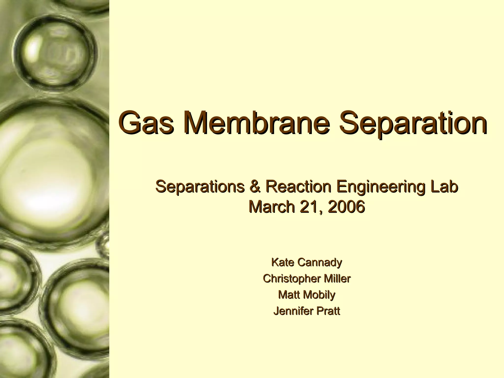
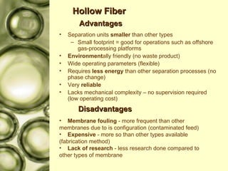
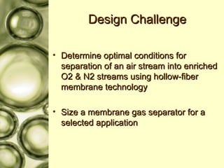
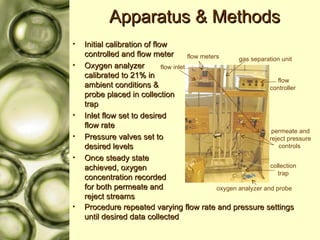
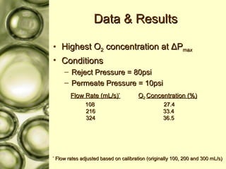
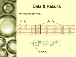
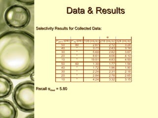
Gas Membrane Separation  Separations & Reaction Engineering Lab March 21, 2006 Kate Cannady Christopher Miller Matt Mobily Jennifer Pratt
Today’s Schedule Introduction & Applications Design Challenge Apparatus & Methods Theory Preliminary Data, Results & Thoughts  on Scale Up Conclusions & Future Plans References
What is Gas Membrane Separation? Separation of a known component into two product streams (known as the permeate and reject, or retentate) through a semi-permeable polymeric membrane   Permeate is oxygen rich (smaller) Reject is nitrogen rich (larger)
Industrial Uses? H 2  Separation H 2 /N 2  separation in ammonia plants & H 2 /hydrocarbon separation in petrochemical applications N 2 /Air Separation CO 2  & H 2 O removal from natural gas Organic vapor removal from air or N 2  streams Inerting Chemical industry products stored in inert atmosphere Reduces risk by removing O 2 Blanketing Uses N 2  to ‘cover’ liquid Prevents vaporization Maintains atmosphere to reduce ignition potential Prevents oxidation or contamination by reducing exposure to atmospheric air
Advantages Separation units  smaller  than other types Small footprint = good for operations such as offshore gas-processing platforms Environment ally friendly (no waste product) Wide operating parameters (flexible) Requires  less energy  than other separation processes (no phase change) Very  reliable   Lacks mechanical complexity – no supervision required (low operating cost) Disadvantages Membrane fouling  - more frequent than other  membranes due to is configuration (contaminated feed)  Expensive  - more so than other types available  (fabrication method) Lack of research  - less research done compared to  other types of membrane  Hollow Fiber
Factors to Consider Properties of component Permeability Relative permeation rates Slow: N 2 , Ar, CO Medium: CO 2 , O 2 Fast: H 2 O, H 2 , He Diffusivity Selectivity Properties of membrane Material Estimated lifetime Size, shape & thickness Operating parameters Feed flow rate Pressure settings
Industrial Hollow Fiber Membrane Typically 300,000 – 500,000 individual fibers OD ~ 300 μ m ID ~ 150 μ m FYI – diameter of a human hair is ~ 100 μ m Housing usually 6-12” diameter and about 40” long
Design Challenge Determine optimal conditions for separation of an air stream into enriched O2 & N2 streams using hollow-fiber membrane technology Size a membrane gas separator for a selected application
Apparatus & Methods Initial calibration of flow controlled and flow meter Oxygen analyzer calibrated to 21% in ambient conditions & probe placed in collection trap Inlet flow set to desired flow rate  Pressure valves set to desired levels Once steady state achieved, oxygen concentration recorded for both permeate and reject streams Procedure repeated varying flow rate and pressure settings until desired data collected gas separation unit collection trap oxygen analyzer and probe flow controller  permeate and reject pressure controls  flow meters  flow inlet
Polysulfone - C 27 H 22 O 4 S Oxygen Permeability P A  = 1.38 Nitrogen Permeability P B  = 0.239 Selectivity α  = P A /P B α  = 1.38/0.238 = 5.8
Theory Flux of A across film: Flux of B across film: x A  = mole fraction of A on high pressure side (reject) y A  = mole fraction of A on low pressure side (permeate) P L  = reject pressure  P V  = permeate pressure P A  = permeability of A P B  = permeability of B t = membrane thickness  A variation of Fick’s…
More Theory… In terms of selectivity:  From before: and become and
And More Theory… So… Recall that
Data & Results Highest O 2  concentration at  Δ P max Conditions Reject Pressure = 80psi Permeate Pressure = 10psi Flow Rate (mL/s) * O 2  Concentration (%) 108   27.4 216   33.4 324   36.5 *  Flow rates adjusted based on calibration (originally 100, 200 and 300 mL/s)
Data & Results For calculating selectivity… P L y A x A P V y B  = (1-y A )
Data & Results Selectivity Results for Collected Data: Recall  α ideal  = 5.80
Conclusions & To Do List Conclusions Highest O2 concentration at largest  Δ P and at higher flow rates Overall experimental selectivity is a bit lower than ideal  Increases with  Δ P, but a change in flow rate does not appear to affect selectivity To Do Determine conditions for highest separation factor More data analysis Scale-Up calculations
References Coker, D.T., Prabhakar, R. and Freeman, B.  Gas Separation Using Polymers.  Chemical Engineering Education.  Winter 2003. 60-67. Membranes For Gas Separation.  Chemical & Engineering News. October 03, 2005. Volume 83: Number 40. 49-57. http://www.cheresources.com/blanketzz.shtml http://www.polymerlabs.com/elsd/images/membrane.gif
? Brilliant! ? ? ? ? ? ? ? ? ? ? ? ? Brilliant!

Gas Membrane Presentation

  • 1.
    Gas Membrane Separation Separations & Reaction Engineering Lab March 21, 2006 Kate Cannady Christopher Miller Matt Mobily Jennifer Pratt
  • 2.
    Today’s Schedule Introduction& Applications Design Challenge Apparatus & Methods Theory Preliminary Data, Results & Thoughts on Scale Up Conclusions & Future Plans References
  • 3.
    What is GasMembrane Separation? Separation of a known component into two product streams (known as the permeate and reject, or retentate) through a semi-permeable polymeric membrane Permeate is oxygen rich (smaller) Reject is nitrogen rich (larger)
  • 4.
    Industrial Uses? H2 Separation H 2 /N 2 separation in ammonia plants & H 2 /hydrocarbon separation in petrochemical applications N 2 /Air Separation CO 2 & H 2 O removal from natural gas Organic vapor removal from air or N 2 streams Inerting Chemical industry products stored in inert atmosphere Reduces risk by removing O 2 Blanketing Uses N 2 to ‘cover’ liquid Prevents vaporization Maintains atmosphere to reduce ignition potential Prevents oxidation or contamination by reducing exposure to atmospheric air
  • 5.
    Advantages Separation units smaller than other types Small footprint = good for operations such as offshore gas-processing platforms Environment ally friendly (no waste product) Wide operating parameters (flexible) Requires less energy than other separation processes (no phase change) Very reliable Lacks mechanical complexity – no supervision required (low operating cost) Disadvantages Membrane fouling - more frequent than other membranes due to is configuration (contaminated feed) Expensive - more so than other types available (fabrication method) Lack of research - less research done compared to other types of membrane Hollow Fiber
  • 6.
    Factors to ConsiderProperties of component Permeability Relative permeation rates Slow: N 2 , Ar, CO Medium: CO 2 , O 2 Fast: H 2 O, H 2 , He Diffusivity Selectivity Properties of membrane Material Estimated lifetime Size, shape & thickness Operating parameters Feed flow rate Pressure settings
  • 7.
    Industrial Hollow FiberMembrane Typically 300,000 – 500,000 individual fibers OD ~ 300 μ m ID ~ 150 μ m FYI – diameter of a human hair is ~ 100 μ m Housing usually 6-12” diameter and about 40” long
  • 8.
    Design Challenge Determineoptimal conditions for separation of an air stream into enriched O2 & N2 streams using hollow-fiber membrane technology Size a membrane gas separator for a selected application
  • 9.
    Apparatus & MethodsInitial calibration of flow controlled and flow meter Oxygen analyzer calibrated to 21% in ambient conditions & probe placed in collection trap Inlet flow set to desired flow rate Pressure valves set to desired levels Once steady state achieved, oxygen concentration recorded for both permeate and reject streams Procedure repeated varying flow rate and pressure settings until desired data collected gas separation unit collection trap oxygen analyzer and probe flow controller permeate and reject pressure controls flow meters flow inlet
  • 10.
    Polysulfone - C27 H 22 O 4 S Oxygen Permeability P A = 1.38 Nitrogen Permeability P B = 0.239 Selectivity α = P A /P B α = 1.38/0.238 = 5.8
  • 11.
    Theory Flux ofA across film: Flux of B across film: x A = mole fraction of A on high pressure side (reject) y A = mole fraction of A on low pressure side (permeate) P L = reject pressure P V = permeate pressure P A = permeability of A P B = permeability of B t = membrane thickness A variation of Fick’s…
  • 12.
    More Theory… Interms of selectivity: From before: and become and
  • 13.
    And More Theory…So… Recall that
  • 14.
    Data & ResultsHighest O 2 concentration at Δ P max Conditions Reject Pressure = 80psi Permeate Pressure = 10psi Flow Rate (mL/s) * O 2 Concentration (%) 108 27.4 216 33.4 324 36.5 * Flow rates adjusted based on calibration (originally 100, 200 and 300 mL/s)
  • 15.
    Data & ResultsFor calculating selectivity… P L y A x A P V y B = (1-y A )
  • 16.
    Data & ResultsSelectivity Results for Collected Data: Recall α ideal = 5.80
  • 17.
    Conclusions & ToDo List Conclusions Highest O2 concentration at largest Δ P and at higher flow rates Overall experimental selectivity is a bit lower than ideal Increases with Δ P, but a change in flow rate does not appear to affect selectivity To Do Determine conditions for highest separation factor More data analysis Scale-Up calculations
  • 18.
    References Coker, D.T.,Prabhakar, R. and Freeman, B. Gas Separation Using Polymers. Chemical Engineering Education. Winter 2003. 60-67. Membranes For Gas Separation. Chemical & Engineering News. October 03, 2005. Volume 83: Number 40. 49-57. http://www.cheresources.com/blanketzz.shtml http://www.polymerlabs.com/elsd/images/membrane.gif
  • 19.
    ? Brilliant! ?? ? ? ? ? ? ? ? ? ? ? Brilliant!