1. The document outlines a project to design and prototype an autonomous floor cleaning robot.
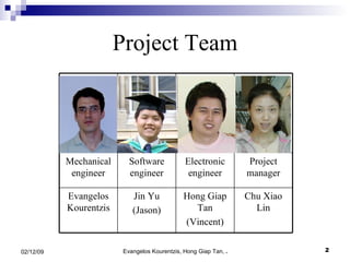
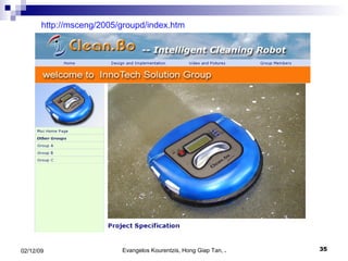
2. It discusses the project team, objectives, scope, assumptions, planning, and key features of the proposed robot called Clean.Bo.
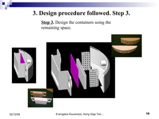
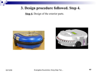
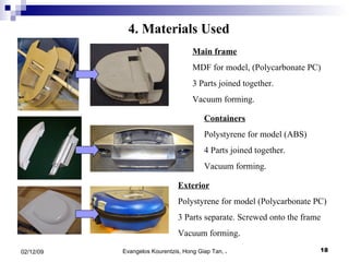
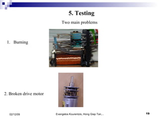
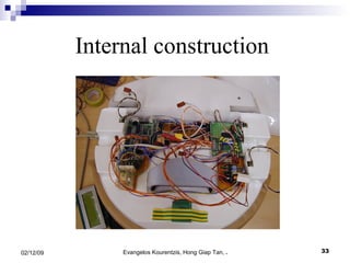
3. The manufacturing procedure and design process are described, including the materials used and testing conducted.


![ppt mini 1[1].pptxsddwsdssdsdsdsddssdssdsdd](https://cdn.slidesharecdn.com/ss_thumbnails/pptmini11-250815141227-c4368069-thumbnail.jpg?width=640&height=640&fit=bounds)