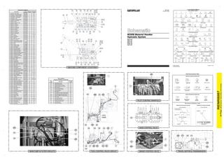
This document provides a schematic for the hydraulic system of a M325D material handler. It includes a legend that identifies the line patterns used for different hydraulic circuits and callouts. A table lists component locations by number and tap locations for pressure sampling by letter. Hydraulic circuit color descriptions are also provided to identify different systems such as the idle pump output, drive pump output, and steering control circuit.
This schematic shows the hydraulic system for a 140M or 160M motor grader. It displays the components, lines, and connections that make up the system. Lines are color coded based on their function. Component callouts provide identification numbers and locations to reference in the service manual. Taps are labeled for measuring pressure or sampling fluid at key points in the system.
This document contains a list of various electrical system components for a vehicle. It includes parts like the starter motor, batteries, alternator, fuses, relays, switches, and wiring diagrams. The list appears to describe the basic electrical circuits involved in starting the vehicle, running accessories, and charging the battery. Diagrams show the wiring connections between the battery, starter, ignition switch, and other core components.
This document provides information on the hydraulic system for a 938G Series II Wheel Loader and IT38G Series II Integrated Toolcarrier, including:
1) A schematic diagram of the hydraulic system with labeled components such as pumps, valves, cylinders and reservoirs.
2) Tables listing the components of the hydraulic system with their schematic location and description.
3) Charts showing the location of hydraulic pressure taps on the machine and their tap descriptions.
The document contains hydraulic symbols, component diagrams and identifies optional configurations for the machine's hydraulic system.
This document provides information on hydraulic system components and symbols for Caterpillar 416E, 422E, and 428E backhoe loaders. It includes a table listing hydraulic components, diagrams of the implement and steering pump and hydraulic circuits, and pages describing the loader and backhoe valves and hydraulic symbols.
This document provides connector and component location information for the electrical system of 773E and 775E off-highway trucks. It includes a chart listing connector locations and numbers, component specifications including switches and senders, and schematic symbols used in wiring diagrams.
SISTEMA ELECTRICOS E HIDROSTÁTICOS DE TRACTORES CATERPILLAR D5KJonny Zambrano
This document provides a schematic and component list for the hydraulic system on Caterpillar D3G, D4G, and D5G track-type tractors. The schematic shows the hydraulic circuits and components including pumps, valves, filters, cylinders and hoses. A table lists 44 hydraulic system components with part numbers and locations on the machine.
The document provides specifications for various off machine switch components including part numbers, functions, actuation and deactuation parameters, and contact positions. It also includes tables listing component identifiers, module identifiers, failure mode identifiers, and electrical schematic symbols and their definitions.
This document provides electrical component information for an excavator, including:
- Component and connector location charts detailing where parts are located on schematics and the machine.
- CID/MID/FMI codes for diagnosing faults in the engine/pump controller, engine controller, and tool controller modules.
- Event codes and their meanings for the engine/pump and engine controllers.
- Specifications for related manuals and an off-machine switch.
This document provides symbols, definitions and location information for electrical schematic components and harness connectors for an excavator. It includes a list of common electrical components with their symbols and brief descriptions as well as charts that show the schematic and physical locations of connectors and individual machine components on the excavator. The purpose is to provide information to aid in understanding electrical system diagrams and locating components in the field.
This document provides a schematic and additional information for the hydraulic system of a 320D and 320D L excavator. The schematic uses lines, symbols and callouts to show the layout and connections between major hydraulic components. These include pumps, motors, cylinders, valves, filters and more. Accompanying text provides additional details on component locations, fluid pressures and flows, and other information to understand the system.
This document provides an interactive schematic for a 320D and 323D excavator attachment. It includes:
- A bookmarks panel to navigate points of interest and machine views via hyperlinks.
- A button in machine views to show all callouts.
- Schematics, machine views, component tables, and other information about the attachment.
- Keyboard shortcuts and screen resolution instructions for optimal viewing.
This document provides connector and component location information for the electrical schematics of a wheel loader. It is divided into three volumes: the cab, canopy, and chassis/engine. Each volume includes a chart that lists components, their location on the schematic, and their physical location on the machine. Additional charts provide the location of connectors on the schematics and descriptions of common error codes.
Ford scort 2000 cc 1998 se alldata informationWilliamserazo
This document provides a diagram and wiring information for the engine controls on a 1998 Ford Escort with a 2.0L SOHC engine. It includes a 3-page wiring diagram identifying various sensors, solenoids, and other components involved in powertrain management and their wire colors. Location information is also provided for many components listed on the diagram.
This document provides a hydraulic schematic for a 325C excavator. It includes:
- A component table that lists each hydraulic component, its part number, machine location, and location on the schematic.
- The schematic diagram labels each hydraulic component and shows how they are connected via hydraulic lines and valves. Line styles indicate different types of hydraulic lines.
- Additional reference information includes fluid power and electrical symbols, and a diagram showing the location of major hydraulic components on the machine.
OBD2 Powertrain Code List (P0200- P0299)Tim Miller
Check the OBD2 code list (P0200 - P0299) to find out what the codes mean on your car.
>> NEXT STEP: https://www.obdadvisor.com/codes/
Visit our site, and type the code in the search box. You will get more information about the code including causes, symptoms, fixes, and repair costs.
Reading and clearing the codes will become easier with a scan tool.
>> READ MORE: https://www.obdadvisor.com/best-obd2-scanner-review/
This article shows a helpful in-depth review of the 9 best OBD2 scan tools from me, an experienced auto mechanic who has used and tested all of them.
This document provides a 3-page schematic for the hydraulic system of a 16M motor grader. It includes a component location table with over 40 components listed along with their part numbers and locations. The schematic itself shows the hydraulic circuit layout and color codes the different circuits. Callouts on the schematic reference components from the table by name and identification number.
This document provides a schematic and component location guide for the hydraulic system of 525C, 535C, and 545C wheel skidders. It includes:
- A diagram of the hydraulic system schematic with labeled components and lines.
- A table listing machine components with their part numbers and locations in the schematic and on the machine.
- Information on tap locations for measuring pressure and sampling fluid.
- Reference pages on fluid power and electrical symbols.
This document provides information about electrical system components for Caterpillar 525C, 535C, and 545C wheel skidder machines. It includes two tables: one listing components and their locations in schematics and on machines, and another listing electrical connectors and their schematic and machine locations. The tables provide key details about components and connectors to help with electrical system troubleshooting and repair.
This document provides a summary of key connectors and their locations for the engine and chassis of a machine. It lists connector numbers from the schematic along with their corresponding machine locations. This allows technicians to easily identify connectors in the field based on the schematic. The chart includes over 30 different connectors ranging from the battery connections to sensors and controls throughout the engine and chassis systems.
New Holland TN60VA TN75VA TN95VA ManualPelicancanupi
This document contains repair manual contents for New Holland TN60VA, TN75VA, and TN95VA tractors. It includes sections on the engine, transmission, clutch, front axle, and other systems. Each section breaks down chapters and subsections in a multi-level contents listing format.
OBD2 Powertrain Code List (P0800- P0899)Tim Miller
This document lists OBD-II codes from P0800 to P0899 related to transmission and transfer case control systems. It includes codes for circuits monitoring sensors and switches related to transmission fluid pressure, clutch position, gear position, switches for park/neutral and drive, and communication circuits between control modules. The codes identify issues such as open circuits, high or low voltage conditions, out of range values, intermittent faults, and transmission component problems.
This document provides a schematic and definitions for the hydraulic system of D3G, D4G, and D5G track-type tractors. It includes a key for line patterns, callouts, component locations listed with part numbers, tap locations listed by letter, and a schematic diagram of the hydraulic circuit layout and components.
The document provides information about an interactive schematic for a machine:
- The Bookmarks panel allows quick navigation between points of interest in the schematic and machine views.
- Clickable blue underlined text are hyperlinks that can be used to navigate.
- A button in the top right of machine views makes all callouts visible.
This document is an electrical wiring diagram for a Cummins ISX engine system on a 379 chassis. It contains a legend listing various components and their corresponding wire labels. The diagram then maps out the wiring between these components, including sensors, solenoids, switches and other devices. Key systems shown include engine controls, HVAC, gauges/displays, cruise control and optional remote features.
New holland l175 skid steer (compact track loader) parts catalogue manualhfjsekekmmd
This document is a parts catalog for skid steer loaders and compact track loaders. It contains a table of contents listing the sections and parts covered in the catalog. The sections include information on the engine, fuel system, electrical system, powertrain, brakes, hydraulics, and chassis/attachments. The parts are organized by section and subsection with part numbers and descriptions provided.
New holland l175 skid steer (compact track loader) parts catalogue manualfjsekdmmeed
This document is a parts catalog for skid steer loaders and compact track loaders. It contains a table of contents listing the sections and parts covered in the catalog. The sections include information on the engine, fuel system, electrical system, powertrain, brakes, hydraulics, and chassis/attachments. The parts are organized by section and subsection with part numbers and descriptions provided.
OBD2 Powertrain Code List (P2700- P2799)Tim Miller
Check the OBD2 code list (P2700 to P2799) to find out what the codes mean on your car.
>> NEXT STEP: https://www.obdadvisor.com/codes/
Visit our site, and type the code in the search box. You will get more information about the code including causes, symptoms, fixes, and repair costs.
Reading and clearing the codes will become easier with a scan tool.
>> READ MORE: https://www.obdadvisor.com/best-obd2-scanner-review/
This article shows a helpful in-depth review of the 9 best OBD2 scan tools from me, an experienced auto mechanic who has used and tested all of them.
This parts catalog covers replacement parts for Cummins Power Generation standard generator models GGMA, GGMB, and GGMC. Parts are grouped and illustrated with reference numbers corresponding to the parts list. Engine parts modified or added by Cummins are identified. Other engine parts must be ordered from the original engine manufacturer. Contact the nearest engine parts distributor for assistance ordering replacement parts not listed.
This document provides a list of wire descriptions and component locations for an excavator electrical system. It includes over 1,000 wires organized by circuit type and over 100 components mapped to their schematic location and physical location on the machine. The wire list details the wire number, color, and description for power circuits, lighting circuits, ground circuits, and more. The component location section cross-references components to their schematic symbol and real-world position on the excavator.
This document provides information about the hydraulic system for Caterpillar 966H and 972H wheel loaders, including:
- A list of remote pressure taps located inside the service center panel for measuring various clutch and system pressures.
- Diagrams and descriptions of key hydraulic components such as pumps, valves, cylinders and their functions.
- Identification and location of hydraulic components in schematics and photos.
- Explanations of hydraulic circuit diagrams and color-coding of fluid lines.
- This is a temporary document and will be replaced by formal service information at a later date.
This document provides a schematic and component location guide for the electrical system of a 777D HHA Off Highway Truck. It lists over 150 components in the electrical system along with their schematic symbols, machine locations on the truck, and wire descriptions/numbers. The components include sensors, switches, solenoids, lamps, motors, and more. They are organized into sections for power distribution, control, ground, and monitoring circuits. Diagrams provide more detail on the machine harness connector and wire descriptions.
This document provides a schematic and component location diagrams for the hydraulic system of a 320D and 320D L excavator. It includes:
- A hydraulic circuit diagram with callouts for components, hydraulic lines colored by circuit, and tap locations for testing and sampling.
- Tables listing hydraulic component descriptions, part numbers, and schematic/machine locations.
- Diagrams showing the machine locations of key hydraulic components like motors, pumps, valves and filters.
- Pages on fluid power and electrical symbols, and hydraulic circuit color descriptions.
The document provides specifications for four enclosed housing clutch-brake modules: CBP-56-22-E, CBP-56-32-E, BP-56-22-E, and BP-56-32-E. It lists their technical data including torque ratings, maximum speeds, voltages, currents, weights, and dimensions. Replacement part numbers and quantities are also provided for the modules.
This document provides the electrical schematic for the 854F-E34T industrial engine. It includes:
- A key of symbols used on the schematic for electrical components and connections.
- Tables listing pin numbers and descriptions for connections on the J1 and J2 connectors to the electronic control module.
- A detailed electrical schematic diagram showing the connections between components of the engine's electrical system, including sensors, actuators, and wiring.
The schematic is intended to provide information on troubleshooting, specifications, and operation of the electrical systems for the 854F-E34T industrial engine. Refer to other service manuals and the component descriptions in the schematic for more details.
The document provides information on several manual valve models for hydraulic systems. It includes specifications, diagrams, and ordering information for 2-way and 3-4 way manual poppet valves, spool valves, and directional control valves. Flow rates range from 7-49 LPM, with operating pressures from 210-350 bar. Materials include hardened steel and some aluminum options.
This document provides schematics and component information for the hydraulic system on a 988G wheel loader. It includes:
- A schematic of the implement and axle oil cooler system with labeled components, lines, and taps.
- A list of the components shown on the schematic with part numbers and machine/schematic locations.
- Fluid power and electrical symbols used in the schematic.
- A second schematic of the steering and brake system with the same details.
The document provides a schematic and component locations for the hydraulic system of a 312D2 and 313D2 excavator. It includes:
- A schematic diagram labeling hydraulic components and lines with callouts and color coding.
- Tables listing the components, their part numbers, locations on the machine and in the schematic.
- Views showing the physical locations of components on the excavator.
- Descriptions of fluid power and electrical symbols used in the schematic.
This document provides information on clutch-brake modules, including replacement parts. It lists specifications for various models of open drip proof clutch-brake, clutch, and brake modules. These models have torque ratings ranging from 8 to 16 lb-in, operate at speeds up to 3600 RPM, and are available for 24 or 90 volt systems. The document also includes an exploded view diagram and lists replacement parts by item number, description, and corresponding module model.
This document provides specifications and part numbers for various clutch-brake modules. It includes technical data on torque, speed, voltage and current for different module models. Exploded diagrams show the internal components of the modules and a table lists replacement parts by item number, quantity, and part description for each module model. Ordering information is provided to purchase the modules and individual replacement parts.
This document contains schematics for the hydraulic system of a motor grader. Volume 1 shows the standard implement control valve configuration and includes components like accumulators, cylinders, pumps, tanks and valves. Volume 2 shows alternate implement control valve configurations and additional components like blade tip cylinders and plow/dozer cylinders. Color codes and line patterns are provided to identify different hydraulic circuits on the schematics.
The document contains diagrams and descriptions of the hydraulic system for a Volvo construction equipment machine. It includes labeled diagrams of the full and brief hydraulic circuits showing the layout of hydraulic components such as pumps, valves, cylinders and filters. It also includes a component list identifying 75 numbered hydraulic components in the system and providing a brief name for each one.
The document provides a diagram and descriptions of various components in a vehicle's MFI control system. It includes labels for electronic control units, sensors, actuators, relays, fuses and their connections. The main components control the engine, fuel injection, ignition, transmission and other systems. Abbreviations are used for the component names and locations.
This document provides a list of component identifiers, module identifiers, and failure mode identifiers for the electrical system of a 966F Series II Wheel Loader. It includes over 100 component identifiers for sensors, switches, and solenoids located throughout the machine. It also lists the module identifiers for the computerized monitoring system and electronic transmission control. Finally, it defines 16 failure mode identifiers and their descriptions that are used for diagnosing issues.
This document provides symbols, definitions, and specifications for electrical schematic components and wiring for a particular excavator model. It includes a key of standard harness and wire symbols as well as charts specifying component locations, connector locations, switch specifications, resistor/sender/solenoid specifications, and wire descriptions including number, color, and function. The purpose is to define and identify the various electrical system parts to aid in troubleshooting and repair work.
This document provides specifications and part numbers for enclosed housing clutch-brake modules and their replacement parts. It includes dimensions, technical data, torque curves, and part lists for various models of clutch-brake and brake-only modules with different voltage and torque ratings. Order numbers are listed to purchase replacement coils and other internal components.
This document provides information about the electrical system schematic and components for Caterpillar 416C, 426C, 428C, 436C, and 438C backhoe loaders. It includes:
- A chart listing electrical components and their locations on the schematic and machine views
- A chart identifying connector locations by number on the schematic and machine
- Specifications for resistors, solenoids, and switches
- A table describing wire colors and their associated functions
This document provides schematics and component information for the hydraulic system on a 777F off-highway truck. It includes two volumes, with the first volume focusing on the braking and hoist systems, and the second likely focusing on other hydraulic systems. The first volume includes schematics, diagrams of component locations, and descriptions of key components such as the brake accumulator, parking brake valve, hoist pump, hoist control valve, slack adjusters, and filters. Pressure taps and diagnostic information are also indicated.
This document provides schematics and location information for electrical components on a 416E backhoe loader. It includes:
- Component location charts showing the schematic location and machine location for electrical components in the cab and engine/chassis.
- Connector location charts showing the schematic location of connectors between harnesses.
- Tables with Component Identifiers (CIDs), Module Identifiers (MIDs), and Fault codes that may be used for troubleshooting.
komatsu Toma presiones de PC 300-8LC.pdfSilvio roman
Este documento proporciona instrucciones para probar y ajustar las presiones de aceite en varios circuitos hidráulicos de un equipo de PC300LC/HD-8. Incluye pasos para medir las presiones de alivio en el equipo de trabajo, giro y traslado, así como para ajustar las válvulas de alivio si es necesario para establecer las presiones correctas. También cubre cómo medir y ajustar específicamente las presiones de alivio para el brazo de bajada del aguilón.
La grúa móvil LTM 1030-2.1 tiene una capacidad de carga máxima de 35 toneladas, una altura de elevación máxima de 44 metros y un radio de trabajo máximo de 40 metros. Cuenta con una pluma telescópica de 30 metros de longitud y plumín lateral doble de hasta 15 metros. El sistema de control LICCON proporciona un manejo de grúa seguro y funcional.
Este documento proporciona especificaciones técnicas detalladas para una excavadora sobre cadenas modelo R 984 C Litronic de la marca TB. Incluye detalles sobre el motor, la cabina, el chasis, el equipo de trabajo, las dimensiones y las capacidades. Algunas características clave son una potencia de motor de 504 kW, una capacidad de cuchara retro de 2,9-10 m3, un peso operativo de 118,600-123,400 kg, y una velocidad máxima de traslación de 2,9 km/h.
Este documento proporciona las especificaciones técnicas de una excavadora hidráulica R 9350, incluyendo detalles sobre su motor diesel, sistema eléctrico, mecanismo de giro, controles hidráulicos, cabina del operador, chasis portador, equipo de trabajo, dimensiones y pesos. Algunas de sus características clave son una potencia de motor de 1120 kW, una capacidad de cuchara retro/frontal de 15,3 a 18 m3, y un peso operativo de 302.000 a 310.000 kg dependiendo del equipo
Este documento proporciona instrucciones para el uso y mantenimiento de un tractor. Explica los controles del tractor y cómo ponerlo en marcha, detenerlo y apagar el motor. También describe cómo purgar las líneas de combustible y realizar tareas básicas de mantenimiento.
catalogo 390 d
Alto nivel de producción sostenida, mejorado.
Incremento de rendimiento, fiabilidad y durabilidad.
Su productividad y disminuir sus costos operativos.
El documento describe una excavadora hidráulica Cat 312D/312D L. Incluye especificaciones del motor Cat C4.2 ACERT de 67 kW, pesos de 12,920-13,450 kg, y características como una estación del operador cómoda, rendimiento líder en la industria, y máxima versatilidad a través de herramientas intercambiables. El documento también cubre detalles sobre el sistema hidráulico, tren de rodaje, facilidad de servicio y opciones para mejorar la productividad y reducir los
Este módulo introduce al estudiante a la excavadora 365C, cubriendo la familiarización con la máquina, ubicación de componentes principales, controles de cabina y operación básica. Incluye normas de seguridad, especificaciones técnicas, puntos de servicio, mantenimiento diario y laboratorios prácticos en la máquina para reforzar los conceptos aprendidos.
Este documento presenta la nueva excavadora Robex 210LC-7A de Hyundai. Cuenta con una cabina cómoda y espaciosa con excelente visibilidad, bajo nivel de ruido y vibraciones, y controles ergonómicos. Incorpora un motor Cummins QSB6.7 Tier III potente y eficiente, así como un sistema hidráulico avanzado para un alto rendimiento y bajos consumos. La máquina fue diseñada para ofrecer máxima potencia, rendimiento y fiabilidad.
El documento describe una excavadora de orugas, incluyendo detalles sobre su cabina cómoda y espaciosa para el operador, su potente motor Cummins QSM11 que cumple con normativas de emisiones, y sus características avanzadas como el sistema CAPO para un control hidráulico eficiente.
The document provides specifications for the Hyundai 9 series earthmoving equipment. It details improvements to the equipment including enhanced visibility, comfort, and controls in the operator cabin. It also describes the machine's powerful and efficient engine, precise hydraulics, and focus on operator preference and performance to improve productivity.
1) El documento describe una excavadora Hyundai serie 9, destacando sus características como un motor potente y eficiente, un sistema hidráulico avanzado para un control preciso y una cabina cómoda. 2) Ofrece detalles técnicos como sus dimensiones, capacidades y especificaciones del motor, sistema hidráulico y componentes. 3) Resalta que la máquina hace que el trabajo sea un placer gracias a su rendimiento, comodidad para el operador y bajos costes de mantenimiento y operación.
This parts manual provides information to order replacement parts for a 220A (3.5T) forklift. It includes 6 sections covering general information, the engine, powertrain, hydraulics, electrical systems, and the frame and body. The manual was produced by Bell Equipment Company to assist with maintenance by providing illustrated part breakdowns and lists. It is important to note that parts and specifications may have changed since the manual was printed.
This maintenance manual provides guidance on maintenance, diagnostics, and use of ZF-FreedomLine transmissions. It addresses common issues users may face and offers suggestions, but does not cover all possible issues. Owners and service technicians must familiarize themselves with the content and follow the warnings and requirements for continued warranty coverage. The manual is provided on an "as is" basis and all warranties are disclaimed. ZF-Friedrichshafen AG is not responsible for issues arising from improper installation, maintenance, repair or use of the transmissions or from use of products from other manufacturers.
Este manual de reparación para motores Diesel DEUTZ D302 contiene instrucciones detalladas para el desmontaje y montaje del motor, así como herramientas y equipos especiales requeridos. Incluye secciones sobre medidas límites para piezas de desgaste, datos técnicos del motor, y secuencias de desmontaje y montaje con fotografías. El objetivo es guiar al personal técnico especializado a través de los procedimientos de reparación de manera segura y efectiva.
Este documento lista una serie de códigos de error para una computadora de control de motor, incluyendo F494 por un tiempo demasiado largo de cierre de la válvula de control de bomba, F420 por una entrada baja del acelerador analógico, y F9C4 por falta de comunicación entre la unidad de control electrónico y el monitor. Adicionalmente, señala códigos de error como F495 por un circuito abierto del solenoide de la bomba y F4EA por un error al apagar la unidad de control electrónico.
This three sentence summary provides the high level information from the document:
The document describes a powershift transmission with three forward speeds and reverse. It includes a torque converter for fine speed control in two ranges, a direct drive in a higher range, and a reversing mechanism using a duplex planetary gear set. The transmission uses fluid clutches and a single countershaft to provide the various speed ranges and forward/reverse while keeping both main shafts rotating in the same direction.
Teletender skytrak model 5030 6034 partsSilvio roman
This document is an illustrated parts manual for ANSI Model 5030 and 6034 equipment from June 1985. It provides information on accessing parts prices and manuals online 24/7 for customer convenience. The online services allow users to look up part prices and availability, identify parts using graphical manuals, order parts, review order status, invoices, shipping information and submit warranty claims. It also lists the worldwide locations of JLG Industries.
Implementing ELDs or Electronic Logging Devices is slowly but surely becoming the norm in fleet management. Why? Well, integrating ELDs and associated connected vehicle solutions like fleet tracking devices lets businesses and their in-house fleet managers reap several benefits. Check out the post below to learn more.
Expanding Access to Affordable At-Home EV Charging by Vanessa WarheitForth
Vanessa Warheit, Co-Founder of EV Charging for All, gave this presentation at the Forth Addressing The Challenges of Charging at Multi-Family Housing webinar on June 11, 2024.
Ever been troubled by the blinking sign and didn’t know what to do?
Here’s a handy guide to dashboard symbols so that you’ll never be confused again!
Save them for later and save the trouble!
EV Charging at MFH Properties by Whitaker JamiesonForth
Whitaker Jamieson, Senior Specialist at Forth, gave this presentation at the Forth Addressing The Challenges of Charging at Multi-Family Housing webinar on June 11, 2024.
What Could Be Behind Your Mercedes Sprinter's Power Loss on Uphill RoadsSprinter Gurus
Unlock the secrets behind your Mercedes Sprinter's uphill power loss with our comprehensive presentation. From fuel filter blockages to turbocharger troubles, we uncover the culprits and empower you to reclaim your vehicle's peak performance. Conquer every ascent with confidence and ensure a thrilling journey every time.
Understanding Catalytic Converter Theft:
What is a Catalytic Converter?: Learn about the function of catalytic converters in vehicles and why they are targeted by thieves.
Why are They Stolen?: Discover the valuable metals inside catalytic converters (such as platinum, palladium, and rhodium) that make them attractive to criminals.
Steps to Prevent Catalytic Converter Theft:
Parking Strategies: Tips on where and how to park your vehicle to reduce the risk of theft, such as parking in well-lit areas or secure garages.
Protective Devices: Overview of various anti-theft devices available, including catalytic converter locks, shields, and alarms.
Etching and Marking: The benefits of etching your vehicle’s VIN on the catalytic converter or using a catalytic converter marking kit to make it traceable and less appealing to thieves.
Surveillance and Monitoring: Recommendations for using security cameras and motion-sensor lights to deter thieves.
Statistics and Insights:
Theft Rates by Borough: Analysis of data to determine which borough in NYC experiences the highest rate of catalytic converter thefts.
Recent Trends: Current trends and patterns in catalytic converter thefts to help you stay aware of emerging hotspots and tactics used by thieves.
Benefits of This Presentation:
Awareness: Increase your awareness about catalytic converter theft and its impact on vehicle owners.
Practical Tips: Gain actionable insights and tips to effectively prevent catalytic converter theft.
Local Insights: Understand the specific risks in different NYC boroughs, helping you take targeted preventive measures.
This presentation aims to equip you with the knowledge and tools needed to protect your vehicle from catalytic converter theft, ensuring you are prepared and proactive in safeguarding your property.
Welcome to ASP Cranes, your trusted partner for crane solutions in Raipur, Chhattisgarh! With years of experience and a commitment to excellence, we offer a comprehensive range of crane services tailored to meet your lifting and material handling needs.
At ASP Cranes, we understand the importance of reliable and efficient crane operations in various industries, from construction and manufacturing to logistics and infrastructure development. That's why we strive to deliver top-notch solutions that enhance productivity, safety, and cost-effectiveness for our clients.
Our services include:
Crane Rental: Whether you need a crawler crane for heavy lifting or a hydraulic crane for versatile operations, we have a diverse fleet of well-maintained cranes available for rent. Our rental options are flexible and can be customized to suit your project requirements.
Crane Sales: Looking to invest in a crane for your business? We offer a wide selection of new and used cranes from leading manufacturers, ensuring you find the perfect equipment to match your needs and budget.
Crane Maintenance and Repair: To ensure optimal performance and safety, regular maintenance and timely repairs are essential for cranes. Our team of skilled technicians provides comprehensive maintenance and repair services to keep your equipment running smoothly and minimize downtime.
Crane Operator Training: Proper training is crucial for safe and efficient crane operation. We offer specialized training programs conducted by certified instructors to equip operators with the skills and knowledge they need to handle cranes effectively.
Custom Solutions: We understand that every project is unique, which is why we offer custom crane solutions tailored to your specific requirements. Whether you need modifications, attachments, or specialized equipment, we can design and implement solutions that meet your needs.
At ASP Cranes, customer satisfaction is our top priority. We are dedicated to delivering reliable, cost-effective, and innovative crane solutions that exceed expectations. Contact us today to learn more about our services and how we can support your project in Raipur, Chhattisgarh, and beyond. Let ASP Cranes be your trusted partner for all your crane needs!
2. RENR8087
30Page,(Dimensions:39inchesx28inches)
THIS SCHEMATIC IS FOR THE M325D MATERIAL HANDLER
PART #: 294-9973 (V) CH02
Components are shown installed on a fully operable machine with the key and engine
off and transmission shifter in neutral.
LINE PATTERNS
Drain / Return Lines
Component Group
Pilot / Load Sensing Pressure
Pressure Line
Attachment
Air Line
CALLOUTS
Taps (Pressure, Sampling,Sensor) by letter
Components by number
YY
52
Refer to the appropriate Service Manual for Troubleshooting, Specifications and Systems Operations
DRAIN / RETURN LINE
HYDRAULIC CIRCUIT COLOR DESCRIPTIONS
IDLE PUMP OUTPUT
DRIVE PUMP OUTPUT
STEERING CONTROL CIRCUIT
PILOT PUMP OUTPUT
OSC CYLINDER LOCK CONTROL CIRCUIT
GRAPPLE OR BUCKET CYLINDER CONTROL CIRCUIT
HYDRAULIC CAB RISER CYLINDER CONTROL CIRCUIT
SUPPLY LINE
GENERATOR CIRCUIT (EAME)
STABILIIZER CYLINDER CONTROL CIRCUIT
STICK CYLINDER CONTROL CIRCUIT
TRANSMISSION CLUTCH CONTROL CIRUIT
BOOM CYLINDER CONTROL CIRCUIT
GENERATOR CIRCUIT (NACD)
STEERING PILOT PUMP OUTPUT
TRANSMISSION OIL CIRCULATION PUMP
HYDRUALIC CAB RISER & GRAPPLE ROTATE SUPPLY CIRCUIT
BRAKE CYLINDER CONTROL CIRCUIT
POWER SHIFT CONTROL CIRCUIT
TRAVEL MOTOR CONTROL CIRCUIT
SWING MOTOR CONTROL CIRCUIT
12345679
A
C
D
E
F
12345679
A
B
C
D
E
F
B
8
8
FF
GG
HH
KK
LL
JJ
EE
BB
AA
CC
DD
SS
TTUU
XX
NN
MM
RR
QQ
PP
B2
P2 P1
DR
A2 B1 A1 PRV1
B2
P2 P1
DR
A2 B1 A1 PRV2
TA
P
PRV3
A2A1 A3 A4 A5 A6 A7 A8
B2B1 B3 B4 B5 B6 B7 B8
C
P T
21
3 2 14
P T
1 4 3 2
P T
P T
12
P T
12
3
PRV(3)
2
1
3
PRV(2)
2
1
3
PRV(1)
2
1
A3A4 A2 A1
M2
BK
P
P1
T1/1PST
Z
T5
SPT1/2MA5A5
INOUT
DR
P
T
A2
A1
B1
B2
P A
T
B
A
G
D
C
E F
N
P
DS2
S1 S2
B1 B2
DS1
A2
S3
S1
T
S4
A4
A1
M1
G1A3 Pm
Pi
G2
M2
Pn2
Ps2
PsM2
Ps1
Pn1
PSm1
M3
DrM
Dr2
M4
DR1
P
L
LD
T
R
P
A
P1 YLD
P
B
P T
CFEF
XA XB
P
PA1PA2 P
M
T
A2 A1
M
LS
T
PB2B2 B1 PB1
A2
A3
B2
A1
B1
B4
PB2
A4
PL3
B3
PL2
PL1
A
B
PB1
DR
DR
DR
T
DR
APi
X
C
DR
T A Pi
X
C
MBLEL G
X
G
MAT2
T1U
M1
B
S
A
K
MAX
MIN
B
MB
MK
EB
EK
MS
Z1
T PP T
Z2
Z1
Z2
MU
B
PG
DR
2
5
A
FINE SWING
4 6
3
1
SWIVEL
BL3T AL4 aL4
BL2
R2 AL3 aL3
BL1
AL1
AL2
aL2 aR1al1 Di Pi BR2BR1 AR1 aR2 AR3AR2 aR3 BR3 R1aR4 Pi1 AR4 BR5
BP3
BP2
BR4
A
AR5 aR5 R3
HR
S1 P T
5
6
bR5bR3 bR4 Di1bR2PL PR bR1Pi5bL1bL2 DSTPi3Di2 Pi2 bL3 Di3HL bL4
OPEN
OPEN
FWD
LOWER
LEFT
OUT
IN
SWINGRIGHT
STABILIZERIN
TRAVELREV
GRAPPLECLOSE
BUCKETCLOSE
BOOM(1)
RAISE
STICK(2)
OUT
SCM
INSTICK(1)OUT
RAISEBOOM(2)
SWING
BRAKE
OSC
AXLE
REST
IMPLEMENT
TRAVEL
MOTOR
CONTROL
A
B
STICK OUT
SW L SW R
STICK IN
BOOM DOWN
BCT CL BCT OP
BOOM UP
DOWN
UP
FWD
REV
STABILIZER
AUXCIRCUIT
FWD
REV
TRAVEL
U
DEG
SWIVEL
4 2 1
3
0
MA6A6
TRAVEL
bL1aL1
aL1
bL1
aL2
aL2
aL2
bR1
aR1
bR1
aR1
bR2
bR2
SCM
bR2
bR3
aR2
aR3
aR2
aR4
aR4
Pi
Pi
FILTER GP
PILOT HYD.
145-7750
FILTER GP
CASE DRAIN
126-2075
VALVE GP
BRAKE CONTROL
249-5527
ACCUMULATOR AS
BRAKE CHARGE
255-8546
ACCUMULATOR AS
BRAKE CHARGE
255-8546
FILTER GP
RETURN OIL
188-4140
VALVE GP
COOLER BYPASS
173-4672
FILTER GP
STEER /PILOT HYD.
145-7750
PUMP GP
MAIN HYD
200-3343
SENSOR AS
IDLER PUMP
PRESSURE
221-8859
SENSOR AS
DRIVE PUMP
PRESSURE
221-8859
PUMP GP
GENERATOR
(EAME)
136-8899
VALVE GP
STEERING
235-0772
VALVE GP
PRIORITY
(STEER/HCR)
188-1814
VALVE GP
TRAVEL ANTI-
CAVITATION
235-0789
VALVE GP
GEN FLOW
CONTROL
(EAME)
242-2956
MOTOR GP
HYD GEN
(EAME)
VALVE GP
HCR/GRAPPLE
CONTROL
274-5501
GRAPPLE
ROTATE
ROTATE
CW
ROTATE
CCW
CAB
LOWER
CAB
RAISE
VALVE AS
HCR CHECK
257-2891
ACCUMULATOR AS
HYD CAB RISER
255-8547
VALVE GP
LOAD CONT
CAB LOWERING
185-1247
CYLINDER GP
HYD CAB RISER
235-8287
VALVE GP
SHUT OFF
(HCR)
226-9860
VALVE GP
HCR/GRAPPLE
PILOT SOLENOIDS
259-7429
(HCR UP)
(HCR DOWN)
VALVE GP
PRIORITY
(PRV1)
232-4102
VALVE GP
PRIORITY
(PRV2)
232-4102
VALVE GP
HEAVY LIFT
SOLENOID
121-6303
VALVE GP
NEGATIVE FLOW
CONTROL SOL
171-0188
VALVE GP
GRAPPLE
FLOW
CONTROL
168-0712
SWITCH AS
GRAPPLE
PILOT PRESSURE
167-3466
MANIFOLD GP
PILOT CONTROL
273-1393
ACCUMULATOR GP
PILOT
8U-6159
SENSOR AS
XMSN CLUTCH
PRESSURE 188-3823
VALVE GP
STICK IN
PRIORITY
(PRV3)
206-3354
VALVE GP
PRESSURE
REDUCING
184-1227
VALVE GP
PILOT
SHUTTLE
185-0462
SWITCH AS
PILOT PRESS
167-3466
VALVE GP
RH JOYSTICK
206-3303
VALVE GP
LH JOYSTICK
206-3304 VALVE GP
TRAVEL PEDAL
237-2261
VALVE GP
AUX PEDAL
112-5704
VALVE GP
STABILZER
HANDLE
235-0781
SWITCH AS
AUX PILOT PRESS
167-3466VALVE GP
AUX SHUTTLE
123-2549
MOTOR GP
SWING
179-9775
VALVE GP
SWING CUSHION
158-9085
VALVE GP
STICK CYLINDER
LOAD CONTROL
292-0394
VALVE GP
STICK CYLINDER
LOAD CONTROL
292-0394
VALVE GP
STICK CYLINDER
DOUBLE CHECK
233 -7881
VALVE GP
REAR STAB CYLINDER
LOAD CONTROL SOL
196-7543
VALVE GP
FRONT STAB CYLINDER
LOAD CONTROL SOL
196-7543
CYLINDER GP
LHR STABILIZER
237-4165
CYLINDER GP
RHR STABILIZER
237-4165
CYLINDER GP
LHFSTABILIZER
237-4165
CYLINDER GP
RHF STABILIZER
237-4165
CYLINDER GP
STICK
WHEELBRAKE
WHEELBRAKE
XMSN GP
241-3686
MOTOR GP
TRAVEL
271-2885
CYLINDER GP
LHR OSC LOCK
236-5773
CYLINDER GP
RHR OSC LOCK
236-5773
ACCUMULATOR GP
OSC AXLE REST
8U-2924
CYLINDER GP
RHF STEER
234-4115
CYLINDER GP
LHF STEER
234-4115
ACCUMULATOR GP
BOOM CYLINDER
225-3394
ACCUMULATOR GP
BOOM CYLINDER
225-3394
AUX
TOOL
VALVE GP
LH BOOM CYL
CHECK
274-4230
VALVE GP
RH BOOM CYL
CHECK
274-4230
VALVE GP
SHUT OFF
(BOOM)
145-7166
CYLINDER GP
LH BOOM
CYLINDER GP
RH BOOM
CONNECTOR GP
ORIFICE (HCR)
257-2980
VALVE GP
MANUAL BOOM
LOWERING
232-7304
VALVE GP
BOOM CYL
HEAD END
RETURN SOL
215-4919
VALVE GP
BOOM CYL
ROD END
RETURN SOL
215-4890
VALVE GP
MAIN CONTROL
274-4231
VALVE GP
FLOW CONTROL
BOOM FLOAT
292-2809
SB
SCM
bR3
bR3
GRAPPLE OR BUCKET
SCM
aR3
aR3
SMART
BOOM
SB
WITHOUT
SMART BOOM
SWITCH AS
SERVICE BRAKE
PRESSURE
252-6677
SWITCH AS
BRAKE OIL ACCUMULATOR
PRESSURE
252-6677
SWITCH AS
PILOT/BOOM DOWN
PRESSURE
167-3466
VALVE GP
PILOT/BOOM
DOWN SOLENOID
185-0472
21
P
B
m2
K
m1
B
K
PUMP GP
GENERATOR
(NACD)
274-5658
MOTOR GP
HYD GEN
(NACD)
251-8483
SWITCH AS
GEN PUMP
PRESSURE
131-9203
EAMENACD
aR4
SB
CYLINDER GP
BUCKET
BR3 AR3
BR3
AR3
bR2
bR3
SCM
aR4
SB
aR3
SCM
SCM
SCM
SCM
SCM
OUT IN
DR
VALVE GP
CAB RISER
FLOW CONTROL
257-2892
WITHOUT
SMART BOOM
STICK REGEN
STICK UNLOADING
NFC
RELIEF
NFC
ORIFICE
VARIABLESWING
PRIORITY
MAIN
RELIEF
STRAIGHT
TRAVEL
NEG FLOW
CONTROL
SOLENOID
BOOM
REGEN
NFC
RELIEF
LINE
RELIEF &
MAKEUP
MEDIUM PRESSURE
UNLOADING VALVE
MEDIUM PRESSURE
SIGNAL RELIEF
POWER
SHIFT PRV
PILOT
MEDIUM
PRESS
CROSS
SENSING
PUMP CONTROL
ACTUATOR
ACTUATOR
PUMP
CONTROL
M