Cash Payment 9602870969 Escort Service in Udaipur Call Girls
Mi sk-910 r-bxq_1101
1. This manual covers only one- and two-channel receivers. For information four-channel receivers, please contact SECO-LARM.
Installation Manual
One- and Two-Channel RF Receivers
The SK-910RBQ and SK-910RB2Q are wireless receivers that meets the growing demand for
receivers with multiple and independently controlled output functions. These RF receivers are
compatible with both code hopping and fixed code transmitters (see page 4 of this manual for a list of
compatible transmitters). The receivers can be used to control a variety of home automation devices
such as garage door openers, lights, motorized gates, lifts, or other devices remotely.
1. Mount the receiver out of sight in a location where it is not exposed to weather or moisture, and
where it is not surrounded by metal. Metal will block the RF signal, resulting in a reduced range.
2. For best range, pull the antenna wire as long and straight as possible. If the receiver receives
interference from local RF activity (e.g., an airport or military base), the antenna wire can be folded.
IMPORTANT: DO NOT CUT THE ANTENNA WIRE.
Installation Notes:
Introduction:
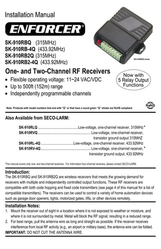
SK-910RBQ (315MHz)
SK-910RB-4Q (433.92MHz)
SK-910RB2Q (315MHz)
SK-910RB2-4Q (433.92MHz)
Flexible operating voltage: 11~24 VAC/VDC
Up to 500ft (152m) range
Independently programmable channels
Also Available from SECO-LARM:
Note: Products with model numbers that end with “Q” or that have a round green “Q” sticker are RoHS compliant.
SK-910RLQ ...........................................Low-voltage, one-channel receiver, 315MHz
SK-910RVQ .........................................................Low-voltage, one-channel receiver,
transistor ground output 315MHZ
SK-910RL-4Q ...................................Low-voltage, one-channel receiver, 433.92MHz
SK-910RV-4Q......................................................Low-voltage, one-channel receiver,
transistor ground output, 433.92MHz
*
*
SK-910RB2Q shown
2. ENFORCER Two-Channel RF Receiver
2 SECO-LARM U.S.A., Inc.
Each channel relay can be programmed for one of five output functions. SK-910RB2Q only: Each channel can be
independently programmed to operate in a different function, depending on the user’s application. The five functions are:
1. 4-Second Timed Output (default) – When the transmitter button is pressed, the relay will turn ON for 4 seconds.
2. Toggle Output – Works much like a toggle switch to turn a device ON & OFF alternately. Press the transmitter button
once, and the relay turns ON. Press the transmitter button again, and the relay turns OFF.
3. Latch Output – Press the transmitter button once, and the relay turns ON and stays ON. The channel relay will remain
ON regardless of whether a compatible transmitter button is pressed again or not. To turn the relay OFF, press the
channel’s mode switch on the receiver once to reset.
4. Validity Output – The channel will turn the relay ON for as long as the transmitter button is pressed.
Note: Due to possible interference or drops in transmitter battery power while the transmitter button is continuously
pressed (even for short periods of time), the receiver may lose the transmitter’s signal and turn the relay OFF.
5. 1-Second Timed Output – When the transmitter button is pressed, the relay will turn ON for 1 second.
1. Press the channel mode switch of the desired channel for 3 seconds or more. The channel’s LED will start to flash
quickly to indicate that it is in learning mode.
2. While the LED is flashing, press the button of the transmitter to be learned one time. The receiver’s channel indicator
LED will flash once to indicate the transmitter button has been successfully learned. After the button has been learned,
the receiver will automatically exit learning mode. To learn further codes, repeat step 1 to re-enter learning mode.
NOTES:
The channel mode switch(es) can be found at the rear of the receiver’s case.
The channel’s indicator LED will flash a maximum of 15 seconds. If no transmitter button is pressed during this time, the
receiver will exit code learning mode, and the LED will turn off.
If the code being learned has already been learned, the channel indicator LED will turn steady ON and then start flashing
again. The code will not be learned a second time.
One channel can learn the codes of a maximum of 15 transmitter buttons. If you attempt to learn a sixteenth transmitter
code, the earliest code learned will be deleted and the new code will be learned.
Code Learning a New Transmitter Button:
Each receiver channel can learn the codes of up to 15 different transmitters on a first-in, first-out basis. Below is the
procedure for code learning a new transmitter button.
Clear Channel Memory:
To clear all codes from a channel’s memory, press the channel’s mode switch for 3 seconds or more until the channel
indicator LED flashes. Release, and then press the switch again for 3 seconds or more until the LED stops flashing. The
LED will then flash twice to indicate that all codes associated with that channel have been deleted.
Display Channel Memory:
To see how many codes have been learned by a channel, press that channel’s mode switch once. The number of codes
stored in the channel’s memory is equal to the number of times the channel indicator LED flashes.
Programming Channel Relay Output Function:
Selecting the relay output function:
Hold down the channel function switch for 3 or more
seconds. The channel’s LED will flash a number of
times equal to the output mode that it is in.
To change a channel’s function, press the channel’s
function switch. Each press moves to the next
function in the sequence as shown in the diagram to
the right.
After changing functions, count the number of times
the channel LED flashes to verify the channel is set
to the correct function.
To exit function programming, hold the appropriate
function switch for 3 seconds, or wait 15 seconds. Note: For a diagram of the PC board, including the location
of the function switch(es), please see Overview, page 3.
Toggle Output
(2 flashes)
Validity Output
(4 flashes)
4-sec (default)
Timed Output
(1 flash)
Latch Output
(3 flashes)
1-sec Timed Output
(5 flashes)
3. ENFORCER Two-Channel RF Receiver
SECO-LARM U.S.A., Inc. 3
SK-910RB2Q shown. SK-910RBQ is the
same, but only has one each: mode
switch; function switch; indicator LED;
channel relay.
Channel Mode Switch Operation (One per Channel):
LED Indication (One per Channel):
Extended Range Antenna (Optional):
The SECO-LARM SK-91ERSDQ extends RF receiver range up to
1,000ft (304m) (open air) with existing remotes. It comes with a 9ft
(2.7m) cable that easily plugs into the 3-pin antenna port located on the
RF receiver.
Note:
If an extended range antenna is used, the ―LP3‖ on the receiver PC
board must be cut.
Actual antenna range will vary greatly depending on the operating
environment.
SK-91ERSDQ
Overview:
(PC board shown. Remove the front cover of the receiver to access the function switch(es) and terminal block.)
Learn mode Press and hold the channel mode switch for three seconds or more.
Clear memory
Press and hold the channel mode switch for three seconds or more, then when the LED starts
flashing, press again for three seconds to delete all previously learned codes.
Reset latched output
If the channel was programmed for latch output, once the relay is turned ON with a transmitter
button, press the channel mode switch of that channel once to turn the relay OFF.
Memory Display
Press and release the channel mode switch to show the number of codes stored. The LED will
flash a number of times corresponding to the number of codes stored.
Steady ON
Receiving signal from a transmitter button during normal operation, or indicates a transmitter
button’s code already exists in the receiver’s memory during code learning.
Fast flash
Receiver is in code-learning mode or channel memory display mode, or during the programming
channel output mode.
One flash A transmitter button code was learned, or receiver channel is in 4-second timed output mode.
Two flashes
All previously learned transmitter buttons were deleted, or receiver channel is in toggle output
mode.
Three flashes Receiver channel is in latched output mode.
Four flashes Receiver channel is in validity output mode.
Five flashes Receiver channel is in 1-second timed output mode.
0~15 flashes
During normal operation, pressing a channel mode switch will cause the channel indicator LED
to flash. Number of flashes indicates the number of transmitter buttons currently stored.
CH 1 CH 2
Brown function switch is
for channel 1 programming.
Red function switch is for
channel 2 programming.
Channel Function Switches
Ch 1 indicator LED
Ch 2 indicator LED
Power input
Ch 1 relay
N.O.
N.C.
COM
N.O.
N.C.
COM
Ch 2 relay
+
—
3-Pin antenna port
LP3 antenna program
loop
Channel 2 mode switch
Channel 1 mode switch
(SK-910RB2Q only)
(SK-910RB2Q only)
(SK-910RB2Q only)
(SK-910RB2Q only)