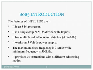
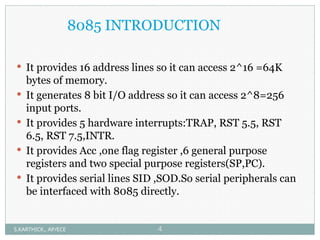
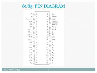
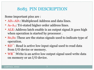
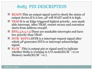
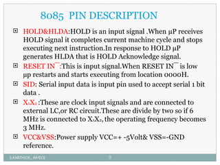
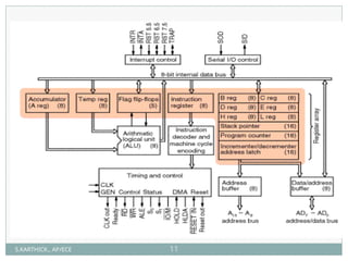
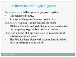
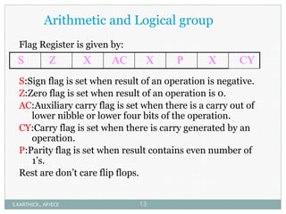
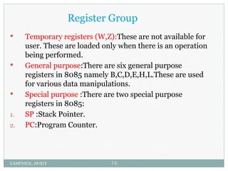
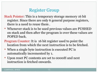
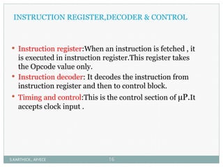
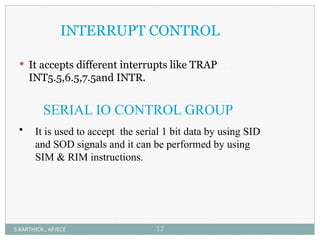
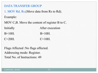
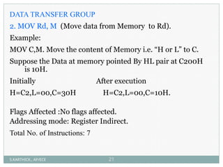
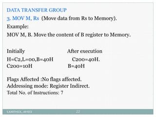
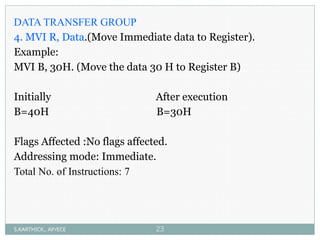
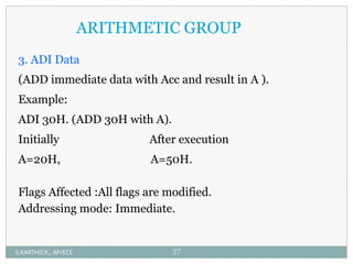
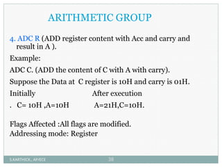
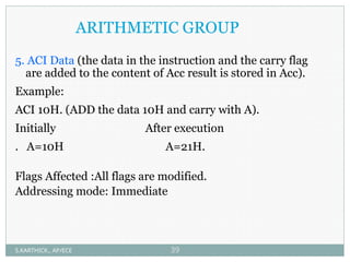
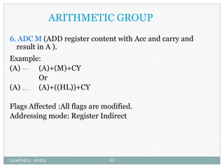
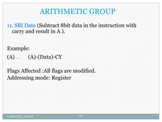
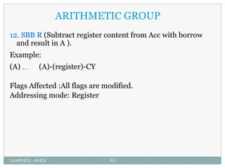
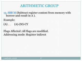
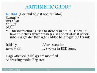
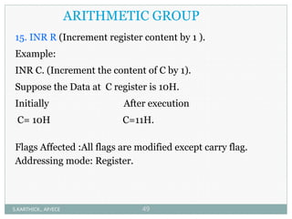
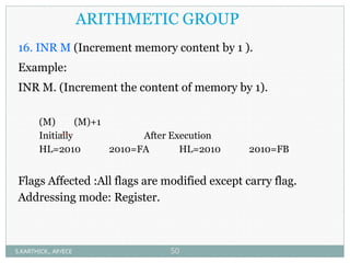
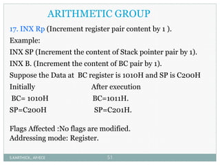
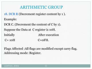
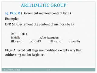
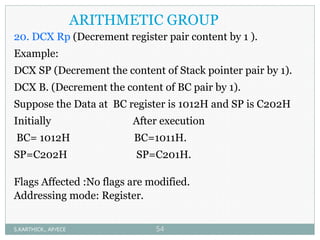
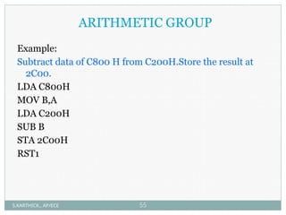
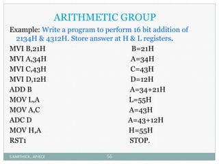
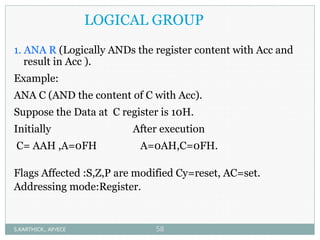
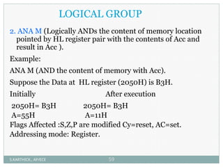
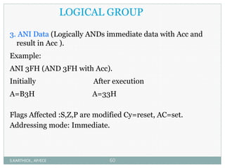
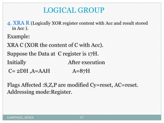
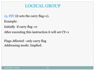
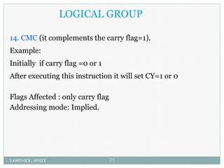
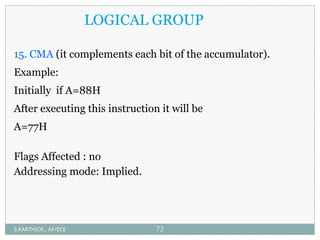
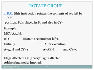
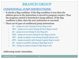
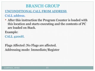
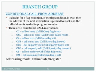
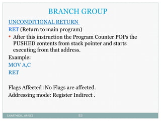
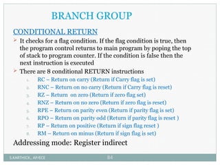
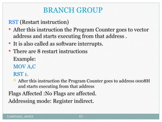
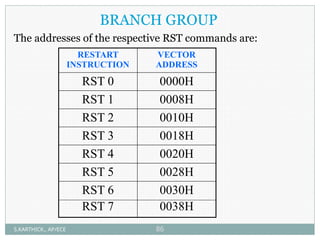
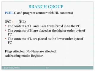
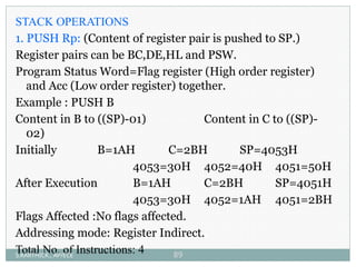
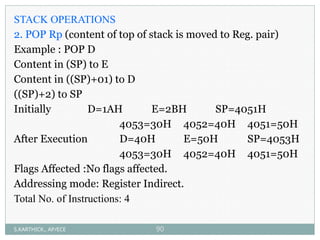
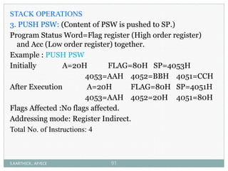
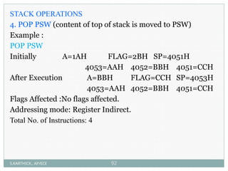
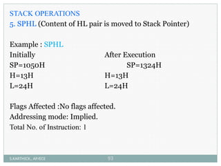
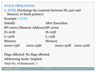
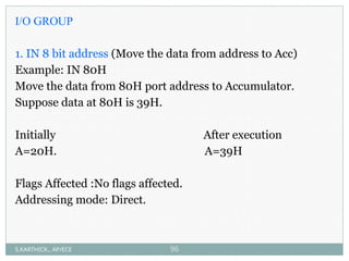
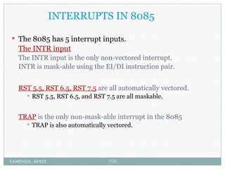
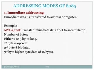
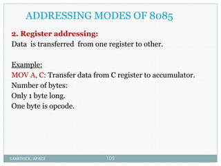
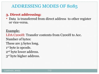
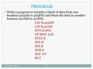
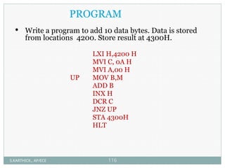
INTRODUCTION TO 8085
S.KARTHICK., AP/ECE 1
8085
INTRODUCTION
S.KARTHICK., AP/ECE 2
8085 INTRODUCTION
The features of INTEL 8085 are :
• It is an 8 bit processor.
• It is a single chip N-MOS device with 40 pins.
• It has multiplexed address and data bus.(AD0-AD7).
• It works on 5 Volt dc power supply.
• The maximum clock frequency is 3 MHz while
minimum frequency is 500kHz.
• It provides 74 instructions with 5 different addressing
modes.
S.KARTHICK., AP/ECE 3
8085 INTRODUCTION
 It provides 16 address lines so it can access 2^16 =64K
bytes of memory.
 It generates 8 bit I/O address so it can access 2^8=256
input ports.
 It provides 5 hardware interrupts:TRAP, RST 5.5, RST
6.5, RST 7.5,INTR.
 It provides Acc ,one flag register ,6 general purpose
registers and two special purpose registers(SP,PC).
 It provides serial lines SID ,SOD.So serial peripherals can
be interfaced with 8085 directly.
S.KARTHICK., AP/ECE 4
8085
PIN DIAGRAM
S.KARTHICK., AP/ECE 5
8085 PIN DIAGRAM
S.KARTHICK., AP/ECE 6
8085 PIN DESCRIPTION
Some important pins are :
 AD0-AD7: Multiplexed Address and data lines.
 A8-A15: Tri-stated higher order address lines.
 ALE: Address latch enable is an output signal.It goes high
when operation is started by processor .
 S0,S1: These are the status signals used to indicate type of
operation.
 RD¯: Read is active low input signal used to read data
from I/O device or memory.
 WR¯:Write is an active low output signal used write data
on memory or an I/O device.
S.KARTHICK., AP/ECE 7
8085 PIN DESCRIPTION
 READY:This an output signal used to check the status of
output device.If it is low, µP will WAIT until it is high.
 TRAP:It is an Edge triggered highest priority , non mask
able interrupt. After TRAP, restart occurs and execution
starts from address 0024H.
 RST5.5,6.5,7.5:These are maskable interrupts and have
low priority than TRAP.
 INTR¯&INTA:INTR is a interrupt request signal after
which µP generates INTA or interrupt acknowledge
signal.
 IO/M¯:This is output pin or signal used to indicate
whether 8085 is working in I/O mode(IO/M¯=1) or
Memory mode(IO/M¯=0 ).
S.KARTHICK., AP/ECE 8
8085 PIN DESCRIPTION
 HOLD&HLDA:HOLD is an input signal .When µP receives
HOLD signal it completes current machine cycle and stops
executing next instruction.In response to HOLD µP
generates HLDA that is HOLD Acknowledge signal.
 RESET IN¯:This is input signal.When RESET IN¯ is low
µp restarts and starts executing from location 0000H.
 SID: Serial input data is input pin used to accept serial 1 bit
data .
 X1X2 :These are clock input signals and are connected to
external LC,or RC circuit.These are divide by two so if 6
MHz is connected to X1X2,the operating frequency becomes
3 MHz.
 VCC&VSS:Power supply VCC=+ -5Volt& VSS=-GND
reference.
S.KARTHICK., AP/ECE 9
8085
ARCHITECTURE
S.KARTHICK., AP/ECE 10
S.KARTHICK., AP/ECE 11
Arithmetic and Logical group
Accumulator: It is 8 bit general purpose register.
 It is connected to ALU.
 So most of the operations are done in Acc.
Temporary register: It is not available for user
 All the arithmetic and logical operations are done in
the temporary register but user can’t access it.
Flag: It is a group of 5 flip flops used to know status of
various operations done.
 The Flag Register along with Accumulator is called
PSW or Program Status Word.
S.KARTHICK., AP/ECE 12
Arithmetic and Logical group
Flag Register is given by:
S:Sign flag is set when result of an operation is negative.
Z:Zero flag is set when result of an operation is 0.
AC:Auxiliary carry flag is set when there is a carry out of
lower nibble or lower four bits of the operation.
CY:Carry flag is set when there is carry generated by an
operation.
P:Parity flag is set when result contains even number of
1’s.
Rest are don’t care flip flops.
S Z X AC X P X CY
S.KARTHICK., AP/ECE 13
Register Group
 Temporary registers (W,Z):These are not available for
user. These are loaded only when there is an operation
being performed.
 General purpose:There are six general purpose
registers in 8085 namely B,C,D,E,H,L.These are used
for various data manipulations.
 Special purpose :There are two special purpose
registers in 8085:
1. SP :Stack Pointer.
2. PC:Program Counter.
S.KARTHICK., AP/ECE 14
Register Group
Stack Pointer: This is a temporary storage memory 16 bit
register. Since there are only 6 general purpose registers,
there is a need to reuse them .
 Whenever stack is to be used previous values are PUSHED
on stack and then after the program is over these values are
POPED back.
Program Counter: It is 16 bit register used to point the
location from which the next instruction is to be fetched.
 When a single byte instruction is executed PC is
automatically incremented by 1.
 Upon reset PC contents are set to 0000H and next
instruction is fetched onwards.
S.KARTHICK., AP/ECE 15
INSTRUCTION REGISTER,DECODER & CONTROL
 Instruction register:When an instruction is fetched , it
is executed in instruction register.This register takes
the Opcode value only.
 Instruction decoder: It decodes the instruction from
instruction register and then to control block.
 Timing and control:This is the control section of µP.It
accepts clock input .
S.KARTHICK., AP/ECE 16
INTERRUPT CONTROL
 It accepts different interrupts like TRAP
INT5.5,6.5,7.5and INTR.
SERIAL IO CONTROL GROUP
• It is used to accept the serial 1 bit data by using SID
and SOD signals and it can be performed by using
SIM & RIM instructions.
S.KARTHICK., AP/ECE 17
8085
INSTRUCTION
SET
S.KARTHICK., AP/ECE 18
DATA TRANSFER
GROUP
INSTRUCTIONS
S.KARTHICK., AP/ECE 19
DATA TRANSFER GROUP
1. MOV Rd, Rs.(Move data from Rs to Rd).
Example:
MOV C,B. Move the content of register B to C.
Initially After execution
B=10H. B=10H.
C=20H. C=10H.
Flags Affected :No flags affected.
Addressing mode: Register.
Total No. of Instructions: 49
S.KARTHICK., AP/ECE 20
DATA TRANSFER GROUP
2. MOV Rd, M (Move data from Memory to Rd).
Example:
MOV C,M. Move the content of Memory i.e. “H or L” to C.
Suppose the Data at memory pointed By HL pair at C200H
is 10H.
Initially After execution
H=C2,L=00,C=30H H=C2,L=00,C=10H.
Flags Affected :No flags affected.
Addressing mode: Register Indirect.
Total No. of Instructions: 7
S.KARTHICK., AP/ECE 21
DATA TRANSFER GROUP
3. MOV M, Rs (Move data from Rs to Memory).
Example:
MOV M, B. Move the content of B register to Memory.
Initially After execution
H=C2,L=00,B=40H C200=40H.
C200=10H B=40H
Flags Affected :No flags affected.
Addressing mode: Register Indirect.
Total No. of Instructions: 7
S.KARTHICK., AP/ECE 22
DATA TRANSFER GROUP
4. MVI R, Data.(Move Immediate data to Register).
Example:
MVI B, 30H. (Move the data 30 H to Register B)
Initially After execution
B=40H B=30H
Flags Affected :No flags affected.
Addressing mode: Immediate.
Total No. of Instructions: 7
S.KARTHICK., AP/ECE 23
DATA TRANSFER GROUP
5. MVI M, Data.(Move Immediate data to Memory).
Example:
MVI M, 40H. (Move the data 40H to Memory address
specified in HL pair)
Initially After execution
H=20H L=50H 2050H=40H
2050H=10H
Flags Affected :No flags affected.
Addressing mode: Register Indirect or Immediate.
Total No. of Instructions: 7
S.KARTHICK., AP/ECE 24
DATA TRANSFER GROUP
6. LXI Rp,16 bit .(Load 16 bit data to Register pair
Immediate).
Example:
LXI SP, C200H. (Load Stack pointer with C200H).
Initially After execution
SP=C800H SP=C200H.
Flags Affected :No flags affected.
Addressing mode: Immediate.
Total No. of Instructions: 4
S.KARTHICK., AP/ECE 25
DATA TRANSFER GROUP
7. STA address.(Store Acc data to address).
Example:
STA C200H. (Move the data from Acc to C200H).
Suppose in Acc the data is 10H.
Initially After execution
A=10H, C200=20H C200=10H , A=10H
Flags Affected :No flags affected.
Addressing mode: Direct.
Total No. of Instruction: 1
S.KARTHICK., AP/ECE 26
DATA TRANSFER GROUP
8. LDA address.(Store Address data to Acc).
Example:
LDA C200H. (Move the data from C200H to Acc).
Suppose in C200 the data is 20H.
Initially After execution
A=10H, C200=20H C200=20H , A=20H
Flags Affected :No flags affected.
Addressing mode: Direct.
Total No. of Instruction: 1
S.KARTHICK., AP/ECE 27
DATA TRANSFER GROUP
9. LHLD address.(Load HL pair with data from address).
Example:
LHLD C200H. (Move the data from C200 to HL pair).
Suppose at C200 the data is 20H,30H .
Initially After execution
H=10H,L=20H H=30H,L=20H.
C200H=20H,C201H=30H C200H=20H,C201H=30H
Flags Affected :No flags affected.
Addressing mode: Direct.
Total No. of Instruction: 1
S.KARTHICK., AP/ECE 28
DATA TRANSFER GROUP
10. SHLD address.(Store the data to Address from HL pair).
Example:
SHLD C200H. (Store the data to C200 from HL pair).
Initially After execution
H=30H,L=60H H=30H,L=60H.
C200H=20H, C201H=40H C200H=60H,C201H=30H
Flags Affected :No flags affected.
Addressing mode: Direct.
Total No. of Instruction: 1
S.KARTHICK., AP/ECE 29
DATA TRANSFER GROUP
11. XCHG (Exchange the data from HL pair to DE pair)
Example : XCHG
Initially After execution
H=20H,L=30H, H=40H,L=70H.
D=40H,E=70H. D=20H,E=30H.
Flags Affected :No flags affected.
Addressing mode: Implied.
Total No. of Instruction: 1
S.KARTHICK., AP/ECE 30
DATA TRANSFER GROUP
12. STAX Rp (Copies the contents of Acc into Memory
location whose address is specified by the register pair)
Example : STAX B
Initially After execution
BC=1020H. A=50H.
A=50H. 1020H=50H.
1020H=10H
Flags Affected :No flags affected.
Addressing mode: Register Indirect.
Total No. of Instructions: 2
S.KARTHICK., AP/ECE 31
DATA TRANSFER GROUP
13. LDAX Rp (Copies the contents of Memory location whose
address is specified by the register pair into Acc)
Example : LDAX D
Initially After execution
DE=2020H. A=30H.
A=10H. 2020H=30H.
2020H=30H
Flags Affected :No flags affected.
Addressing mode: Register Indirect.
Total No. of Instructions: 2
S.KARTHICK., AP/ECE 32
DATA TRANSFER GROUP
Example: Write a program to exchange contents of memory
location D000H to D001H
LDA D000H Load Acc with data from D000
MOV B,A Move the data to B
LDA D001H Load Acc with data from D001
STA D000H Store Acc data at D000
MOV A,B Move B’s data to A
STA D001H Store data from D000 to D001
RST Stop.
S.KARTHICK., AP/ECE 33
ARITHMETIC
GROUP
INSTRUCTIONS
S.KARTHICK., AP/ECE 34
ARITHMETIC GROUP
1. ADD R (ADD register content with Acc and result in A ).
Example:
ADD C. (ADD the content of C with A).
Suppose the Data at C register is 10H.
Initially After execution
C= 10H, A=10H A=20H, C=10H.
Flags Affected :All flags are modified.
Addressing mode: Register
S.KARTHICK., AP/ECE 35
ARITHMEIC GROUP
2. ADD M
(ADD H or L Reg content with Acc and result in A ).
Example:
ADD M. (ADD the content of HL with A).
 Suppose the Data at memory pointed by HL register
1020H is 10H.
Initially After execution
. H= 10H ,L=20H . H=10H,L=20H.
A=20H,C=10H. A=30H.
Flags Affected :All flags are modified.
Addressing mode: Register Indirect.
S.KARTHICK., AP/ECE 36
ARITHMETIC GROUP
3. ADI Data
(ADD immediate data with Acc and result in A ).
Example:
ADI 30H. (ADD 30H with A).
Initially After execution
A=20H, A=50H.
Flags Affected :All flags are modified.
Addressing mode: Immediate.
S.KARTHICK., AP/ECE 37
ARITHMETIC GROUP
4. ADC R (ADD register content with Acc and carry and
result in A ).
Example:
ADC C. (ADD the content of C with A with carry).
Suppose the Data at C register is 10H and carry is 01H.
Initially After execution
. C= 10H ,A=10H A=21H,C=10H.
Flags Affected :All flags are modified.
Addressing mode: Register
S.KARTHICK., AP/ECE 38
ARITHMETIC GROUP
5. ACI Data (the data in the instruction and the carry flag
are added to the content of Acc result is stored in Acc).
Example:
ACI 10H. (ADD the data 10H and carry with A).
Initially After execution
. A=10H A=21H.
Flags Affected :All flags are modified.
Addressing mode: Immediate
S.KARTHICK., AP/ECE 39
ARITHMETIC GROUP
6. ADC M (ADD register content with Acc and carry and
result in A ).
Example:
(A) (A)+(M)+CY
Or
(A) (A)+((HL))+CY
Flags Affected :All flags are modified.
Addressing mode: Register Indirect
S.KARTHICK., AP/ECE 40
ARITHMETIC GROUP
7. DAD Rp (Add specified register pair with HL pair)
Example:DAD D.(Add the content of E with L and that of
D with H register and result in HL pair)
 Suppose the content of HL pair is H=20H ,L=40H and
DE pair is D=30H, E=10H.
Initially After execution
H=20H ,L=40H H=50H ,L=50H
D=30H, E=10H D=30H, E=10H
Flags Affected :Only carry flag is modified.
Addressing mode: Register.
S.KARTHICK., AP/ECE 41
ARITHMETIC GROUP
8. SUB R (Subtract register content from Acc and result in
A ).
Example:
SUB B. (Subtract the content of B from A ).
Suppose the Data at B register is 10H .
Initially After execution
. B= 10H ,A=20H A=10H,B=10H.
Flags Affected :All flags are modified.
Addressing mode: Register
S.KARTHICK., AP/ECE 42
ARITHMETIC GROUP
9. SUI Data
(Subtract immediate data from Acc and result in A ).
Example:
SUI 30H. (Subtract 30H from A).
Initially After execution
A=80H, A=50H.
Flags Affected :All flags are modified.
Addressing mode: Immediate
S.KARTHICK., AP/ECE 43
ARITHMETIC GROUP
10. SUB M (Content of memory addressed by HL pair is
subtracted from Acc. Result stored in Acc ).
Example:
(A) (A)-(M)
Or
(A) (A)-((HL))
Flags Affected :All flags are modified.
Addressing mode: Register Indirect
S.KARTHICK., AP/ECE 44
ARITHMETIC GROUP
11. SBI Data (Subtract 8bit data in the instruction with
carry and result in A ).
Example:
(A) (A)-(Data)-CY
Flags Affected :All flags are modified.
Addressing mode: Register
S.KARTHICK., AP/ECE 45
ARITHMETIC GROUP
12. SBB R (Subtract register content from Acc with borrow
and result in A ).
Example:
(A) (A)-(register)-CY
Flags Affected :All flags are modified.
Addressing mode: Register
S.KARTHICK., AP/ECE 46
ARITHMETIC GROUP
13. SBB M (Subtract register content from memory with
borrow and result in A ).
Example:
(A) (A)-(M)-CY
Flags Affected :All flags are modified.
Addressing mode: Register indirect
S.KARTHICK., AP/ECE 47
ARITHMETIC GROUP
14. DAA (Decimal Adjust Accumulator)
Example:
MVI A,12H
ADI 39H
DAA .
 This instruction is used to store result in BCD form. If
lower nibble is greater than 9 ,6 is added while if upper
nibble is greater than 9,6 is added to it to get BCD result.
Initially After execution
12+39=4B 12+39=51 in BCD form.
Flags Affected :All flags are modified.
Addressing mode: Register
S.KARTHICK., AP/ECE 48
ARITHMETIC GROUP
15. INR R (Increment register content by 1 ).
Example:
INR C. (Increment the content of C by 1).
Suppose the Data at C register is 10H.
Initially After execution
C= 10H C=11H.
Flags Affected :All flags are modified except carry flag.
Addressing mode: Register.
S.KARTHICK., AP/ECE 49
ARITHMETIC GROUP
16. INR M (Increment memory content by 1 ).
Example:
INR M. (Increment the content of memory by 1).
(M) (M)+1
Initially After Execution
HL=2010 2010=FA HL=2010 2010=FB
Flags Affected :All flags are modified except carry flag.
Addressing mode: Register.
S.KARTHICK., AP/ECE 50
ARITHMETIC GROUP
17. INX Rp (Increment register pair content by 1 ).
Example:
INX SP (Increment the content of Stack pointer pair by 1).
INX B. (Increment the content of BC pair by 1).
Suppose the Data at BC register is 1010H and SP is C200H
Initially After execution
BC= 1010H BC=1011H.
SP=C200H SP=C201H.
Flags Affected :No flags are modified.
Addressing mode: Register.
S.KARTHICK., AP/ECE 51
ARITHMETIC GROUP
18. DCR R (Decrement register content by 1 ).
Example:
DCR C. (Decrement the content of C by 1).
Suppose the Data at C register is 10H.
Initially After execution
C= 10H C=0FH.
Flags Affected :All flags are modified except carry flag.
Addressing mode: Register.
S.KARTHICK., AP/ECE 52
ARITHMETIC GROUP
19. DCR M (Decrement memory content by 1 ).
Example:
INR M. (decrement the content of memory by 1).
(M) (M)-1
Initially After Execution
HL=2010 2010=FA HL=2010 2010=F9
Flags Affected :All flags are modified except carry flag.
Addressing mode: Register.
S.KARTHICK., AP/ECE 53
ARITHMETIC GROUP
20. DCX Rp (Decrement register pair content by 1 ).
Example:
DCX SP (Decrement the content of Stack pointer pair by 1).
DCX B. (Decrement the content of BC pair by 1).
Suppose the Data at BC register is 1012H and SP is C202H
Initially After execution
BC= 1012H BC=1011H.
SP=C202H SP=C201H.
Flags Affected :No flags are modified.
Addressing mode: Register.
S.KARTHICK., AP/ECE 54
ARITHMETIC GROUP
Example:
Subtract data of C800 H from C200H.Store the result at
2C00.
LDA C800H
MOV B,A
LDA C200H
SUB B
STA 2C00H
RST1
S.KARTHICK., AP/ECE 55
ARITHMETIC GROUP
Example: Write a program to perform 16 bit addition of
2134H & 4312H. Store answer at H & L registers.
MVI B,21H B=21H
MVI A,34H A=34H
MVI C,43H C=43H
MVI D,12H D=12H
ADD B A=34+21H
MOV L,A L=55H
MOV A,C A=43H
ADC D A=43+12H
MOV H,A H=55H
RST1 STOP.
S.KARTHICK., AP/ECE 56
LOGICAL GROUP
INSTRUCTIONS
S.KARTHICK., AP/ECE 57
LOGICAL GROUP
1. ANA R (Logically ANDs the register content with Acc and
result in Acc ).
Example:
ANA C (AND the content of C with Acc).
Suppose the Data at C register is 10H.
Initially After execution
C= AAH ,A=0FH A=0AH,C=0FH.
Flags Affected :S,Z,P are modified Cy=reset, AC=set.
Addressing mode:Register.
S.KARTHICK., AP/ECE 58
LOGICAL GROUP
2. ANA M (Logically ANDs the content of memory location
pointed by HL register pair with the contents of Acc and
result in Acc ).
Example:
ANA M (AND the content of memory with Acc).
Suppose the Data at HL register (2050H) is B3H.
Initially After execution
2050H= B3H 2050H= B3H
A=55H A=11H
Flags Affected :S,Z,P are modified Cy=reset, AC=set.
Addressing mode: Register.
S.KARTHICK., AP/ECE 59
LOGICAL GROUP
3. ANI Data (Logically ANDs immediate data with Acc and
result in Acc ).
Example:
ANI 3FH (AND 3FH with Acc).
Initially After execution
A=B3H A=33H
Flags Affected :S,Z,P are modified Cy=reset, AC=set.
Addressing mode: Immediate.
S.KARTHICK., AP/ECE 60
LOGICAL GROUP
4. XRA R (Logically XOR register content with Acc and result stored
in Acc ).
Example:
XRA C (XOR the content of C with Acc).
Suppose the Data at C register is 17H.
Initially After execution
C= 2DH ,A=AAH A=87H
Flags Affected :S,Z,P are modified Cy=reset, AC=reset.
Addressing mode:Register.
S.KARTHICK., AP/ECE 61
LOGICAL GROUP
5. XRA M (Logically XOR memory content with Acc and result stored
in Acc ).
Example:
XRA M (XOR the content of memory with A).
Initially HL=2050H, 2050H=B3H, A=55H
After execution A=E6H
Flags Affected :S,Z,P are modified Cy=reset, AC=reset.
Addressing mode:Register.
S.KARTHICK., AP/ECE 62
LOGICAL GROUP
6. XRI Data (Logically XOR 8bit data with Acc and result stored in
Acc ).
Example:
XRI 39H (XOR 39H with Acc).
Initially A=B3H
After execution A=8AH
Flags Affected :S,Z,P are modified Cy=reset, AC=reset.
Addressing mode:Immediate.
S.KARTHICK., AP/ECE 63
LOGICAL GROUP
7. ORA R (Logically OR register content with Acc and result stored in
Acc ).
Example:
ORA B (OR the B register contents with Acc).
Initially After execution
B=12H B=12H
A=AAH A=BAH
Flags Affected :S,Z,P are modified Cy=reset,AC=reset.
Addressing mode:Register.
S.KARTHICK., AP/ECE 64
LOGICAL GROUP
8. ORA M (Logically OR memory content with Acc and result stored
in Acc ).
Example:
ORA M (OR the memory content with Acc).
Initially After execution
HL=2050H HL=2050H
2050H= B3H 2050H= B3H
A=55H A=F7H
Flags Affected :S,Z,P are modified Cy=reset, AC=reset.
Addressing mode:Register indirect.
S.KARTHICK., AP/ECE 65
LOGICAL GROUP
9. ORI Data (Logically OR immediate data with Acc and result stored
in Acc ).
Example:
ORI 08H (OR 08H with Acc).
Initially After execution
A=B3H A=BBH
Flags Affected :S,Z,P are modified Cy=reset, AC=set.
Addressing mode: Immediate.
S.KARTHICK., AP/ECE 66
LOGICAL GROUP
10. CMP R (Compare register content with Acc and result in Acc ).
Example:
CMP C (Compare the content of C with A).
A=B8H C=B9H
(A)=(A)-(R)
Here A<C so carry flag will set after the execution
Flags Affected :all flags affected.
Addressing mode:Register.
S.KARTHICK., AP/ECE 67
LOGICAL GROUP
11. CMP M (Compare contents of memory location and the contents
of Acc and result in Acc ).
Example:
CMP C (Compare the content of C with A).
A=B8H HL=2050H 2050H=B8H
(A)=(A)-(M)
Here A=M so zero flag will set after the execution
Flags Affected :all flags are affected.
Addressing mode:Register indirect.
S.KARTHICK., AP/ECE 68
LOGICAL GROUP
12. CPI Data (Compare immediate data with Acc ).
Example:
CPI 30H (Compare the content of C with A).
Initially A=BAH
(A)=(A)-(data)
Here A>data so zero and carry flags will reset after the
execution of the instruction
Flags Affected : all flags are affected..
Addressing mode: Immediate.
S.KARTHICK., AP/ECE 69
LOGICAL GROUP
13. STC (it sets the carry flag=1).
Example:
Initially if carry flag =0
After executing this instruction it will set CY=1
Flags Affected : only carry flag
Addressing mode: Implied.
S.KARTHICK., AP/ECE 70
LOGICAL GROUP
14. CMC (it complements the carry flag=1).
Example:
Initially if carry flag =0 or 1
After executing this instruction it will set CY=1 or 0
Flags Affected : only carry flag
Addressing mode: Implied.
S.KARTHICK., AP/ECE 71
LOGICAL GROUP
15. CMA (it complements each bit of the accumulator).
Example:
Initially if A=88H
After executing this instruction it will be
A=77H
Flags Affected : no
Addressing mode: Implied.
S.KARTHICK., AP/ECE 72
ROTATE GROUP
INSTRUCTIONS
S.KARTHICK., AP/ECE 73
ROTATE GROUP
1. RAL (this instruction rotates the contents of acc left by
one
position. B7 is placed in B0 and also in CY).
Example:
MOV A,57H.
RLC (Rotate accumulator left).
Initially After execution
A=57H and CY=1 A=AEH and CY=0
Flags Affected :Only carry flag is affected.
Addressing mode: Implied.
S.KARTHICK., AP/ECE 74
ROTATE GROUP
2. RAR (this instruction rotates the contents of acc right by
one position. B0 is placed in B7 and also in CY).
Example:
MOV A,9AH.
RRC (Rotate accumulator right).
Initially After execution
A=9AH , CY=1 A=4DH, CY=0.
Flags Affected :Only carry flag is affected.
Addressing mode:Implied.
S.KARTHICK., AP/ECE 75
ROTATE GROUP
3. RLC (Rotate accumulator left with carry. B7 is placed in
CY and CY is placed in B0).
Example:
MOV A,ADH.
RAL (Rotate accumulator left with carry).
Initially After execution
A=ADH , CY=0 A=5AH, CY=1.
Flags Affected :Only carry flag is affected.
Addressing mode:Implied.
S.KARTHICK., AP/ECE 76
ROTATE GROUP
4. RRC (Rotate accumulator right with carry, B0 is placed in
CY and CY is placed in B7 ).
Example:
MOV A,A3H.
RAL (Rotate accumulator left with carry).
Initially After execution
A=A3H , CY=0 A=51H, CTY=1.
Flags Affected :Only carry flag is affected.
Addressing mode:Implied.
S.KARTHICK., AP/ECE 77
BRANCH GROUP
INSTRUCTIONS
S.KARTHICK., AP/ECE 78
UNCONDITIONAL JUMP INSTRUCTIONS.
JMP address
 After execution, the address given in the instruction is
moved to Program counter. Now the processor starts
executing the instructions stored in this address
Example:
JMP C200H.
Processor starts executes from address C200H..
Flags Affected :No Flags are affected.
Addressing mode: Immediate.
BRANCH GROUP
S.KARTHICK., AP/ECE 79
BRANCH GROUP
CONDITIONAL JUMP INSTRUCTIONS.
 It checks a flag condition. If the flag condition is true then the
address given in the instruction is moved to program counter. Thus
the program control is branched to jump address. If the flag
condition is false, then the next instruction is executed.
 There are 8 types of conditional jump instructions
1. JC – jump on carry (Jump if Carry flag is set)
2. JNC – jump on no carry (Jump if Carry flag is reset)
3. JZ – jump on zero (Jump if zero flag set)
4. JNZ – jump on no zero (Jump if zero flag is reset)
5. JPE – jump on parity even (Jump if parity flag is set)
6. JPO – jump on parity odd (Jump if parity flag is reset)
7. JP – jump on positive (Jump if sign flag reset )
8. JM – jump on minus (Jump if sign flag is set)
Addressing mode: Immediate.
S.KARTHICK., AP/ECE 80
BRANCH GROUP
UNCONDITIONAL CALL FROM ADDRESS
CALL address.
 After this instruction the Program Counter is loaded with
this location and starts executing and the contents of PC
are loaded on Stack.
Example:
CALL 4200H.
Flags Affected :No Flags are affected.
Addressing mode: Immediate/Register
S.KARTHICK., AP/ECE 81
BRANCH GROUP
CONDITIONAL CALL FROM ADDRESS
 It checks for a flag condition. If the flag condition is true, then
the address of the next instruction is pushed to stack and the
call address is loaded in program counter.
 There are 8 conditional CALL instructions
1. CC – call on carry (Call if Carry flag is set)
2. CNC – call on no carry (Call if Carry flag is reset)
3. CZ – call on zero (Call if zero flag set)
4. CNZ – call on no zero (Call if zero flag is reset)
5. CPE – call on parity even (Call if parity flag is set)
6. CPO – call on parity odd (Call if parity flag is reset )
7. CP – call on positive (Call if sign flag reset )
8. CM – call on minus (Call if sign flag is set)
Addressing mode: Immediate/Register
S.KARTHICK., AP/ECE 82
BRANCH GROUP
UNCONDITIONAL RETURN
RET (Return to main program)
 After this instruction the Program Counter POPs the
PUSHED contents from stack pointer and starts
executing from that address.
Example:
MOV A,C
RET
Flags Affected :No Flags are affected.
Addressing mode: Register Indirect .
S.KARTHICK., AP/ECE 83
BRANCH GROUP
CONDITIONAL RETURN
 It checks for a flag condition. If the flag condition is true, then
the program control returns to main program by poping the top
of stack to program counter. If the condition is false then the
next instruction is executed
 There are 8 conditional RETURN instructions
1. RC – Return on carry (Return if Carry flag is set)
2. RNC – Return on no carry (Return if Carry flag is reset)
3. RZ – Return on zero (Return if zero flag set)
4. RNZ – Return on no zero (Return if zero flag is reset)
5. RPE – Return on parity even (Return if parity flag is set)
6. RPO – Return on parity odd (Return if parity flag is reset )
7. RP – Return on positive (Return if sign flag reset )
8. RM – Return on minus (Return if sign flag is set)
Addressing mode: Register indirect
S.KARTHICK., AP/ECE 84
BRANCH GROUP
RST (Restart instruction)
 After this instruction the Program Counter goes to vector
address and starts executing from that address .
 It is also called as software interrupts.
 There are 8 restart instructions
Example:
MOV A,C
RST 1.
 After this instruction the Program Counter goes to address 0008H
and starts executing from that address
Flags Affected :No Flags are affected.
Addressing mode: Register indirect.
S.KARTHICK., AP/ECE 85
BRANCH GROUP
The addresses of the respective RST commands are:
RESTART
INSTRUCTION
VECTOR
ADDRESS
RST 0 0000H
RST 1 0008H
RST 2 0010H
RST 3 0018H
RST 4 0020H
RST 5 0028H
RST 6
RST 7
0030H
0038H
S.KARTHICK., AP/ECE 86
BRANCH GROUP
PCHL (Load program counter with HL contents)
(PC) (HL)
 The contents of H and L are transferred in to the PC.
 The contents of H are placed as the higher order byte of
PC.
 The contents of L are placed as the lower order byte of
PC
Flags Affected :No Flags are affected.
Addressing mode: Register.
S.KARTHICK., AP/ECE 87
STACK
OPERATIONS
S.KARTHICK., AP/ECE 88
STACK OPERATIONS
1. PUSH Rp: (Content of register pair is pushed to SP.)
Register pairs can be BC,DE,HL and PSW.
Program Status Word=Flag register (High order register)
and Acc (Low order register) together.
Example : PUSH B
Content in B to ((SP)-01) Content in C to ((SP)-
02)
Initially B=1AH C=2BH SP=4053H
4053=30H 4052=40H 4051=50H
After Execution B=1AH C=2BH SP=4051H
4053=30H 4052=1AH 4051=2BH
Flags Affected :No flags affected.
Addressing mode: Register Indirect.
Total No. of Instructions: 4
S.KARTHICK., AP/ECE 89
STACK OPERATIONS
2. POP Rp (content of top of stack is moved to Reg. pair)
Example : POP D
Content in (SP) to E
Content in ((SP)+01) to D
((SP)+2) to SP
Initially D=1AH E=2BH SP=4051H
4053=30H 4052=40H 4051=50H
After Execution D=40H E=50H SP=4053H
4053=30H 4052=40H 4051=50H
Flags Affected :No flags affected.
Addressing mode: Register Indirect.
Total No. of Instructions: 4
S.KARTHICK., AP/ECE 90
STACK OPERATIONS
3. PUSH PSW: (Content of PSW is pushed to SP.)
Program Status Word=Flag register (High order register)
and Acc (Low order register) together.
Example : PUSH PSW
Initially A=20H FLAG=80H SP=4053H
4053=AAH 4052=BBH 4051=CCH
After Execution A=20H FLAG=80H SP=4051H
4053=AAH 4052=20H 4051=80H
Flags Affected :No flags affected.
Addressing mode: Register Indirect.
Total No. of Instructions: 4
S.KARTHICK., AP/ECE 91
STACK OPERATIONS
4. POP PSW (content of top of stack is moved to PSW)
Example :
POP PSW
Initially A=1AH FLAG=2BH SP=4051H
4053=AAH 4052=BBH 4051=CCH
After Execution A=BBH FLAG=CCH SP=4053H
4053=AAH 4052=BBH 4051=CCH
Flags Affected :No flags affected.
Addressing mode: Register Indirect.
Total No. of Instructions: 4
S.KARTHICK., AP/ECE 92
STACK OPERATIONS
5. SPHL (Content of HL pair is moved to Stack Pointer)
Example : SPHL
Initially After Execution
SP=1050H SP=1324H
H=13H H=13H
L=24H L=24H
Flags Affected :No flags affected.
Addressing mode: Implied.
Total No. of Instruction: 1
S.KARTHICK., AP/ECE 93
STACK OPERATIONS
6. XTHL (Exchange the contents between HL pair and
Memory or Stack pointer)
Example : XTHL
Initially After Execution
SP=2000 (Memory Address)SP=2000
H=20H H=25H
L=30H L=15H
Memory Memory
2000=15H 2001=25H 2000=30H 2001=20H
Flags Affected :No flags affected.
Addressing mode: Implied.
Total No. of Instruction: 1
S.KARTHICK., AP/ECE 94
INPUT/OUTPUT
INSTRUCTIONS
S.KARTHICK., AP/ECE 95
I/O GROUP
1. IN 8 bit address (Move the data from address to Acc)
Example: IN 80H
Move the data from 80H port address to Accumulator.
Suppose data at 80H is 39H.
Initially After execution
A=20H. A=39H
Flags Affected :No flags affected.
Addressing mode: Direct.
S.KARTHICK., AP/ECE 96
I/O GROUP
2. OUT 8 bit address (Move the data from Acc to address)
Example: OUT 80H
Move the data from Acc to port address 80H.
Suppose data at Acc is 39H.
Initially After execution
A=39H. 80=10H. A=39H,80=39H.
Flags Affected :No flags affected.
Addressing mode: Direct.
S.KARTHICK., AP/ECE 97
MACHINE CONTROL
INSTRUCTIONS
S.KARTHICK., AP/ECE 98
MACHINE CONTROL INSTRUCTIONS
1. DI – Disable Interrupts.
 The interrupt enable flip-flop is reset and all the
interrupts except the TRAP are disabled. No flags are
affected.
Example: DI
2. EI – Enable Interrupts.
 The interrupt enable flip-flop is set and all interrupts are
enabled. No flags are affected. This instruction is
necessary to re-enable the interrupts (except TRAP).
Example: EI
S.KARTHICK., AP/ECE 99
MACHINE CONTROL INSTRUCTIONS
3. HLT – Halt program execution
 The CPU finishes executing the current instruction and
halts any further execution.
An interrupt or reset is necessary to exit from the halt
state.
Example: HLT
4. NOP – No Operation
 No operation is performed. The instruction is fetched
and decoded. However no operation is executed.
Example: NOP
S.KARTHICK., AP/ECE 100
MACHINE CONTROL INSTRUCTIONS
5. SIM – Set Interrupt Mask
 This is a multipurpose instruction and used to implement
the 8085 interrupts RST7.5, 6.5, 5.5, and SOD (serial data
output). The instruction interprets the accumulator
contents as follows.
Example: SIM
S.KARTHICK., AP/ECE 101
MACHINE CONTROL INSTRUCTIONS
S.KARTHICK., AP/ECE 102
MACHINE CONTROL INSTRUCTIONS
6. RIM – Read Interrupt Mask
 This is a multipurpose instruction used to read the
status of interrupts 7.5, 6.5, 5.5 and read serial data
input bit. The instruction loads eight bits in the
accumulator with the following interpretations.
Example: RIM
S.KARTHICK., AP/ECE 103
INTERRUPTS
IN 8085
S.KARTHICK., AP/ECE 104
INTERRUPTS IN 8085
 Interrupt is a process where an external device can get
the attention of the microprocessor.
 Interrupts can be classified into two types:
1. Maskable Interrupts (Can be delayed or
Rejected)
2. Non-Maskable Interrupts (Can not be delayed
or Rejected)
 Interrupts can also be classified into:
1. Vectored (the address of the service routine is
hard-wired)
2. Non-vectored (the address of the service routine
needs to be supplied externally by the device)
S.KARTHICK., AP/ECE 105
INTERRUPTS IN 8085
 The 8085 has 5 interrupt inputs.
The INTR input
The INTR input is the only non-vectored interrupt.
INTR is mask-able using the EI/DI instruction pair.
RST 5.5, RST 6.5, RST 7.5 are all automatically vectored.
 RST 5.5, RST 6.5, and RST 7.5 are all maskable.
TRAP is the only non-mask-able interrupt in the 8085
 TRAP is also automatically vectored.
S.KARTHICK., AP/ECE 106
ADDRESSING
MODES OF 8085
S.KARTHICK., AP/ECE 107
ADDRESSING MODES OF 8085
1. Immediate addressing:
Immediate data is transferred to address or register.
Example:
MVI A,20H: Transfer immediate data 20H to accumulator.
Number of bytes:
Either 2 or 3 bytes long.
1st
byte is opcode.
2nd
byte 8 bit data .
3rd
byte higher byte data of 16 bytes.
S.KARTHICK., AP/ECE 108
ADDRESSING MODES OF 8085
2. Register addressing:
Data is transferred from one register to other.
Example:
MOV A, C: Transfer data from C register to accumulator.
Number of bytes:
Only 1 byte long.
One byte is opcode.
S.KARTHICK., AP/ECE 109
ADDRESSING MODES OF 8085
3. Direct addressing:
 Data is transferred from direct address to other register
or vice-versa.
Example:
LDA C200H: Transfer contents from C200H to Acc.
Number of bytes:
These are 3 bytes long.
1st
byte is opcode.
2nd
byte lower address.
3rd
byte higher address.
S.KARTHICK., AP/ECE 110
ADDRESSING MODES OF 8085
4. Indirect addressing:
 Data is transferred from address pointed by the data in
a register to other register or vice-versa.
Example:
MOV A, M: Move contents from address pointed by M to
Acc.
Number of bytes:
These are 3 bytes long.
1st
byte is opcode.
2nd
byte lower address.
3rd
byte higher address.
S.KARTHICK., AP/ECE 111
ADDRESSING MODES OF 8085
5. Implied addressing:
 These doesn’t require any operand. The data is specified
in Opcode itself.
Example:
RAL: Rotate left with carry.
No. of Bytes: These are single byte instruction or Opcode
only.
S.KARTHICK., AP/ECE 112
PROGRAMMING
OF 8085
S.KARTHICK., AP/ECE 113
MVI C,00H
LHLD 5300
XCHG
LHLD 5302
DAD D
JNC Loop
INR C
Loop: SHLD 5500
MOV A, C
STA 5502
HLT
PROGRAM
• To perform 16 bit Addition
S.KARTHICK., AP/ECE 114
PROGRAM
 Write a program to transfer a block of data from one
location (4050H to 405FH) and Store the data in another
location (4170H to 417FH).
LXI H,4050H
LXI B,4170H
MVI D,0FH
UP MOV A,M
STAX B
INX H
INX B
DCR D
JNZ UP
HLT
S.KARTHICK., AP/ECE 115
PROGRAM
 Write a program to add 10 data bytes. Data is stored
from locations 4200. Store result at 4300H.
LXI H,4200 H
MVI C, 0A H
MVI A,00 H
UP MOV B,M
ADD B
INX H
DCR C
JNZ UP
STA 4300H
HLT
S.KARTHICK., AP/ECE 116

8085 microprocessor introduction in details

  • 1.
  • 2.
  • 3.
    8085 INTRODUCTION The featuresof INTEL 8085 are : • It is an 8 bit processor. • It is a single chip N-MOS device with 40 pins. • It has multiplexed address and data bus.(AD0-AD7). • It works on 5 Volt dc power supply. • The maximum clock frequency is 3 MHz while minimum frequency is 500kHz. • It provides 74 instructions with 5 different addressing modes. S.KARTHICK., AP/ECE 3
  • 4.
    8085 INTRODUCTION  Itprovides 16 address lines so it can access 2^16 =64K bytes of memory.  It generates 8 bit I/O address so it can access 2^8=256 input ports.  It provides 5 hardware interrupts:TRAP, RST 5.5, RST 6.5, RST 7.5,INTR.  It provides Acc ,one flag register ,6 general purpose registers and two special purpose registers(SP,PC).  It provides serial lines SID ,SOD.So serial peripherals can be interfaced with 8085 directly. S.KARTHICK., AP/ECE 4
  • 5.
  • 6.
  • 7.
    8085 PIN DESCRIPTION Someimportant pins are :  AD0-AD7: Multiplexed Address and data lines.  A8-A15: Tri-stated higher order address lines.  ALE: Address latch enable is an output signal.It goes high when operation is started by processor .  S0,S1: These are the status signals used to indicate type of operation.  RD¯: Read is active low input signal used to read data from I/O device or memory.  WR¯:Write is an active low output signal used write data on memory or an I/O device. S.KARTHICK., AP/ECE 7
  • 8.
    8085 PIN DESCRIPTION READY:This an output signal used to check the status of output device.If it is low, µP will WAIT until it is high.  TRAP:It is an Edge triggered highest priority , non mask able interrupt. After TRAP, restart occurs and execution starts from address 0024H.  RST5.5,6.5,7.5:These are maskable interrupts and have low priority than TRAP.  INTR¯&INTA:INTR is a interrupt request signal after which µP generates INTA or interrupt acknowledge signal.  IO/M¯:This is output pin or signal used to indicate whether 8085 is working in I/O mode(IO/M¯=1) or Memory mode(IO/M¯=0 ). S.KARTHICK., AP/ECE 8
  • 9.
    8085 PIN DESCRIPTION HOLD&HLDA:HOLD is an input signal .When µP receives HOLD signal it completes current machine cycle and stops executing next instruction.In response to HOLD µP generates HLDA that is HOLD Acknowledge signal.  RESET IN¯:This is input signal.When RESET IN¯ is low µp restarts and starts executing from location 0000H.  SID: Serial input data is input pin used to accept serial 1 bit data .  X1X2 :These are clock input signals and are connected to external LC,or RC circuit.These are divide by two so if 6 MHz is connected to X1X2,the operating frequency becomes 3 MHz.  VCC&VSS:Power supply VCC=+ -5Volt& VSS=-GND reference. S.KARTHICK., AP/ECE 9
  • 10.
  • 11.
  • 12.
    Arithmetic and Logicalgroup Accumulator: It is 8 bit general purpose register.  It is connected to ALU.  So most of the operations are done in Acc. Temporary register: It is not available for user  All the arithmetic and logical operations are done in the temporary register but user can’t access it. Flag: It is a group of 5 flip flops used to know status of various operations done.  The Flag Register along with Accumulator is called PSW or Program Status Word. S.KARTHICK., AP/ECE 12
  • 13.
    Arithmetic and Logicalgroup Flag Register is given by: S:Sign flag is set when result of an operation is negative. Z:Zero flag is set when result of an operation is 0. AC:Auxiliary carry flag is set when there is a carry out of lower nibble or lower four bits of the operation. CY:Carry flag is set when there is carry generated by an operation. P:Parity flag is set when result contains even number of 1’s. Rest are don’t care flip flops. S Z X AC X P X CY S.KARTHICK., AP/ECE 13
  • 14.
    Register Group  Temporaryregisters (W,Z):These are not available for user. These are loaded only when there is an operation being performed.  General purpose:There are six general purpose registers in 8085 namely B,C,D,E,H,L.These are used for various data manipulations.  Special purpose :There are two special purpose registers in 8085: 1. SP :Stack Pointer. 2. PC:Program Counter. S.KARTHICK., AP/ECE 14
  • 15.
    Register Group Stack Pointer:This is a temporary storage memory 16 bit register. Since there are only 6 general purpose registers, there is a need to reuse them .  Whenever stack is to be used previous values are PUSHED on stack and then after the program is over these values are POPED back. Program Counter: It is 16 bit register used to point the location from which the next instruction is to be fetched.  When a single byte instruction is executed PC is automatically incremented by 1.  Upon reset PC contents are set to 0000H and next instruction is fetched onwards. S.KARTHICK., AP/ECE 15
  • 16.
    INSTRUCTION REGISTER,DECODER &CONTROL  Instruction register:When an instruction is fetched , it is executed in instruction register.This register takes the Opcode value only.  Instruction decoder: It decodes the instruction from instruction register and then to control block.  Timing and control:This is the control section of µP.It accepts clock input . S.KARTHICK., AP/ECE 16
  • 17.
    INTERRUPT CONTROL  Itaccepts different interrupts like TRAP INT5.5,6.5,7.5and INTR. SERIAL IO CONTROL GROUP • It is used to accept the serial 1 bit data by using SID and SOD signals and it can be performed by using SIM & RIM instructions. S.KARTHICK., AP/ECE 17
  • 18.
  • 19.
  • 20.
    DATA TRANSFER GROUP 1.MOV Rd, Rs.(Move data from Rs to Rd). Example: MOV C,B. Move the content of register B to C. Initially After execution B=10H. B=10H. C=20H. C=10H. Flags Affected :No flags affected. Addressing mode: Register. Total No. of Instructions: 49 S.KARTHICK., AP/ECE 20
  • 21.
    DATA TRANSFER GROUP 2.MOV Rd, M (Move data from Memory to Rd). Example: MOV C,M. Move the content of Memory i.e. “H or L” to C. Suppose the Data at memory pointed By HL pair at C200H is 10H. Initially After execution H=C2,L=00,C=30H H=C2,L=00,C=10H. Flags Affected :No flags affected. Addressing mode: Register Indirect. Total No. of Instructions: 7 S.KARTHICK., AP/ECE 21
  • 22.
    DATA TRANSFER GROUP 3.MOV M, Rs (Move data from Rs to Memory). Example: MOV M, B. Move the content of B register to Memory. Initially After execution H=C2,L=00,B=40H C200=40H. C200=10H B=40H Flags Affected :No flags affected. Addressing mode: Register Indirect. Total No. of Instructions: 7 S.KARTHICK., AP/ECE 22
  • 23.
    DATA TRANSFER GROUP 4.MVI R, Data.(Move Immediate data to Register). Example: MVI B, 30H. (Move the data 30 H to Register B) Initially After execution B=40H B=30H Flags Affected :No flags affected. Addressing mode: Immediate. Total No. of Instructions: 7 S.KARTHICK., AP/ECE 23
  • 24.
    DATA TRANSFER GROUP 5.MVI M, Data.(Move Immediate data to Memory). Example: MVI M, 40H. (Move the data 40H to Memory address specified in HL pair) Initially After execution H=20H L=50H 2050H=40H 2050H=10H Flags Affected :No flags affected. Addressing mode: Register Indirect or Immediate. Total No. of Instructions: 7 S.KARTHICK., AP/ECE 24
  • 25.
    DATA TRANSFER GROUP 6.LXI Rp,16 bit .(Load 16 bit data to Register pair Immediate). Example: LXI SP, C200H. (Load Stack pointer with C200H). Initially After execution SP=C800H SP=C200H. Flags Affected :No flags affected. Addressing mode: Immediate. Total No. of Instructions: 4 S.KARTHICK., AP/ECE 25
  • 26.
    DATA TRANSFER GROUP 7.STA address.(Store Acc data to address). Example: STA C200H. (Move the data from Acc to C200H). Suppose in Acc the data is 10H. Initially After execution A=10H, C200=20H C200=10H , A=10H Flags Affected :No flags affected. Addressing mode: Direct. Total No. of Instruction: 1 S.KARTHICK., AP/ECE 26
  • 27.
    DATA TRANSFER GROUP 8.LDA address.(Store Address data to Acc). Example: LDA C200H. (Move the data from C200H to Acc). Suppose in C200 the data is 20H. Initially After execution A=10H, C200=20H C200=20H , A=20H Flags Affected :No flags affected. Addressing mode: Direct. Total No. of Instruction: 1 S.KARTHICK., AP/ECE 27
  • 28.
    DATA TRANSFER GROUP 9.LHLD address.(Load HL pair with data from address). Example: LHLD C200H. (Move the data from C200 to HL pair). Suppose at C200 the data is 20H,30H . Initially After execution H=10H,L=20H H=30H,L=20H. C200H=20H,C201H=30H C200H=20H,C201H=30H Flags Affected :No flags affected. Addressing mode: Direct. Total No. of Instruction: 1 S.KARTHICK., AP/ECE 28
  • 29.
    DATA TRANSFER GROUP 10.SHLD address.(Store the data to Address from HL pair). Example: SHLD C200H. (Store the data to C200 from HL pair). Initially After execution H=30H,L=60H H=30H,L=60H. C200H=20H, C201H=40H C200H=60H,C201H=30H Flags Affected :No flags affected. Addressing mode: Direct. Total No. of Instruction: 1 S.KARTHICK., AP/ECE 29
  • 30.
    DATA TRANSFER GROUP 11.XCHG (Exchange the data from HL pair to DE pair) Example : XCHG Initially After execution H=20H,L=30H, H=40H,L=70H. D=40H,E=70H. D=20H,E=30H. Flags Affected :No flags affected. Addressing mode: Implied. Total No. of Instruction: 1 S.KARTHICK., AP/ECE 30
  • 31.
    DATA TRANSFER GROUP 12.STAX Rp (Copies the contents of Acc into Memory location whose address is specified by the register pair) Example : STAX B Initially After execution BC=1020H. A=50H. A=50H. 1020H=50H. 1020H=10H Flags Affected :No flags affected. Addressing mode: Register Indirect. Total No. of Instructions: 2 S.KARTHICK., AP/ECE 31
  • 32.
    DATA TRANSFER GROUP 13.LDAX Rp (Copies the contents of Memory location whose address is specified by the register pair into Acc) Example : LDAX D Initially After execution DE=2020H. A=30H. A=10H. 2020H=30H. 2020H=30H Flags Affected :No flags affected. Addressing mode: Register Indirect. Total No. of Instructions: 2 S.KARTHICK., AP/ECE 32
  • 33.
    DATA TRANSFER GROUP Example:Write a program to exchange contents of memory location D000H to D001H LDA D000H Load Acc with data from D000 MOV B,A Move the data to B LDA D001H Load Acc with data from D001 STA D000H Store Acc data at D000 MOV A,B Move B’s data to A STA D001H Store data from D000 to D001 RST Stop. S.KARTHICK., AP/ECE 33
  • 34.
  • 35.
    ARITHMETIC GROUP 1. ADDR (ADD register content with Acc and result in A ). Example: ADD C. (ADD the content of C with A). Suppose the Data at C register is 10H. Initially After execution C= 10H, A=10H A=20H, C=10H. Flags Affected :All flags are modified. Addressing mode: Register S.KARTHICK., AP/ECE 35
  • 36.
    ARITHMEIC GROUP 2. ADDM (ADD H or L Reg content with Acc and result in A ). Example: ADD M. (ADD the content of HL with A).  Suppose the Data at memory pointed by HL register 1020H is 10H. Initially After execution . H= 10H ,L=20H . H=10H,L=20H. A=20H,C=10H. A=30H. Flags Affected :All flags are modified. Addressing mode: Register Indirect. S.KARTHICK., AP/ECE 36
  • 37.
    ARITHMETIC GROUP 3. ADIData (ADD immediate data with Acc and result in A ). Example: ADI 30H. (ADD 30H with A). Initially After execution A=20H, A=50H. Flags Affected :All flags are modified. Addressing mode: Immediate. S.KARTHICK., AP/ECE 37
  • 38.
    ARITHMETIC GROUP 4. ADCR (ADD register content with Acc and carry and result in A ). Example: ADC C. (ADD the content of C with A with carry). Suppose the Data at C register is 10H and carry is 01H. Initially After execution . C= 10H ,A=10H A=21H,C=10H. Flags Affected :All flags are modified. Addressing mode: Register S.KARTHICK., AP/ECE 38
  • 39.
    ARITHMETIC GROUP 5. ACIData (the data in the instruction and the carry flag are added to the content of Acc result is stored in Acc). Example: ACI 10H. (ADD the data 10H and carry with A). Initially After execution . A=10H A=21H. Flags Affected :All flags are modified. Addressing mode: Immediate S.KARTHICK., AP/ECE 39
  • 40.
    ARITHMETIC GROUP 6. ADCM (ADD register content with Acc and carry and result in A ). Example: (A) (A)+(M)+CY Or (A) (A)+((HL))+CY Flags Affected :All flags are modified. Addressing mode: Register Indirect S.KARTHICK., AP/ECE 40
  • 41.
    ARITHMETIC GROUP 7. DADRp (Add specified register pair with HL pair) Example:DAD D.(Add the content of E with L and that of D with H register and result in HL pair)  Suppose the content of HL pair is H=20H ,L=40H and DE pair is D=30H, E=10H. Initially After execution H=20H ,L=40H H=50H ,L=50H D=30H, E=10H D=30H, E=10H Flags Affected :Only carry flag is modified. Addressing mode: Register. S.KARTHICK., AP/ECE 41
  • 42.
    ARITHMETIC GROUP 8. SUBR (Subtract register content from Acc and result in A ). Example: SUB B. (Subtract the content of B from A ). Suppose the Data at B register is 10H . Initially After execution . B= 10H ,A=20H A=10H,B=10H. Flags Affected :All flags are modified. Addressing mode: Register S.KARTHICK., AP/ECE 42
  • 43.
    ARITHMETIC GROUP 9. SUIData (Subtract immediate data from Acc and result in A ). Example: SUI 30H. (Subtract 30H from A). Initially After execution A=80H, A=50H. Flags Affected :All flags are modified. Addressing mode: Immediate S.KARTHICK., AP/ECE 43
  • 44.
    ARITHMETIC GROUP 10. SUBM (Content of memory addressed by HL pair is subtracted from Acc. Result stored in Acc ). Example: (A) (A)-(M) Or (A) (A)-((HL)) Flags Affected :All flags are modified. Addressing mode: Register Indirect S.KARTHICK., AP/ECE 44
  • 45.
    ARITHMETIC GROUP 11. SBIData (Subtract 8bit data in the instruction with carry and result in A ). Example: (A) (A)-(Data)-CY Flags Affected :All flags are modified. Addressing mode: Register S.KARTHICK., AP/ECE 45
  • 46.
    ARITHMETIC GROUP 12. SBBR (Subtract register content from Acc with borrow and result in A ). Example: (A) (A)-(register)-CY Flags Affected :All flags are modified. Addressing mode: Register S.KARTHICK., AP/ECE 46
  • 47.
    ARITHMETIC GROUP 13. SBBM (Subtract register content from memory with borrow and result in A ). Example: (A) (A)-(M)-CY Flags Affected :All flags are modified. Addressing mode: Register indirect S.KARTHICK., AP/ECE 47
  • 48.
    ARITHMETIC GROUP 14. DAA(Decimal Adjust Accumulator) Example: MVI A,12H ADI 39H DAA .  This instruction is used to store result in BCD form. If lower nibble is greater than 9 ,6 is added while if upper nibble is greater than 9,6 is added to it to get BCD result. Initially After execution 12+39=4B 12+39=51 in BCD form. Flags Affected :All flags are modified. Addressing mode: Register S.KARTHICK., AP/ECE 48
  • 49.
    ARITHMETIC GROUP 15. INRR (Increment register content by 1 ). Example: INR C. (Increment the content of C by 1). Suppose the Data at C register is 10H. Initially After execution C= 10H C=11H. Flags Affected :All flags are modified except carry flag. Addressing mode: Register. S.KARTHICK., AP/ECE 49
  • 50.
    ARITHMETIC GROUP 16. INRM (Increment memory content by 1 ). Example: INR M. (Increment the content of memory by 1). (M) (M)+1 Initially After Execution HL=2010 2010=FA HL=2010 2010=FB Flags Affected :All flags are modified except carry flag. Addressing mode: Register. S.KARTHICK., AP/ECE 50
  • 51.
    ARITHMETIC GROUP 17. INXRp (Increment register pair content by 1 ). Example: INX SP (Increment the content of Stack pointer pair by 1). INX B. (Increment the content of BC pair by 1). Suppose the Data at BC register is 1010H and SP is C200H Initially After execution BC= 1010H BC=1011H. SP=C200H SP=C201H. Flags Affected :No flags are modified. Addressing mode: Register. S.KARTHICK., AP/ECE 51
  • 52.
    ARITHMETIC GROUP 18. DCRR (Decrement register content by 1 ). Example: DCR C. (Decrement the content of C by 1). Suppose the Data at C register is 10H. Initially After execution C= 10H C=0FH. Flags Affected :All flags are modified except carry flag. Addressing mode: Register. S.KARTHICK., AP/ECE 52
  • 53.
    ARITHMETIC GROUP 19. DCRM (Decrement memory content by 1 ). Example: INR M. (decrement the content of memory by 1). (M) (M)-1 Initially After Execution HL=2010 2010=FA HL=2010 2010=F9 Flags Affected :All flags are modified except carry flag. Addressing mode: Register. S.KARTHICK., AP/ECE 53
  • 54.
    ARITHMETIC GROUP 20. DCXRp (Decrement register pair content by 1 ). Example: DCX SP (Decrement the content of Stack pointer pair by 1). DCX B. (Decrement the content of BC pair by 1). Suppose the Data at BC register is 1012H and SP is C202H Initially After execution BC= 1012H BC=1011H. SP=C202H SP=C201H. Flags Affected :No flags are modified. Addressing mode: Register. S.KARTHICK., AP/ECE 54
  • 55.
    ARITHMETIC GROUP Example: Subtract dataof C800 H from C200H.Store the result at 2C00. LDA C800H MOV B,A LDA C200H SUB B STA 2C00H RST1 S.KARTHICK., AP/ECE 55
  • 56.
    ARITHMETIC GROUP Example: Writea program to perform 16 bit addition of 2134H & 4312H. Store answer at H & L registers. MVI B,21H B=21H MVI A,34H A=34H MVI C,43H C=43H MVI D,12H D=12H ADD B A=34+21H MOV L,A L=55H MOV A,C A=43H ADC D A=43+12H MOV H,A H=55H RST1 STOP. S.KARTHICK., AP/ECE 56
  • 57.
  • 58.
    LOGICAL GROUP 1. ANAR (Logically ANDs the register content with Acc and result in Acc ). Example: ANA C (AND the content of C with Acc). Suppose the Data at C register is 10H. Initially After execution C= AAH ,A=0FH A=0AH,C=0FH. Flags Affected :S,Z,P are modified Cy=reset, AC=set. Addressing mode:Register. S.KARTHICK., AP/ECE 58
  • 59.
    LOGICAL GROUP 2. ANAM (Logically ANDs the content of memory location pointed by HL register pair with the contents of Acc and result in Acc ). Example: ANA M (AND the content of memory with Acc). Suppose the Data at HL register (2050H) is B3H. Initially After execution 2050H= B3H 2050H= B3H A=55H A=11H Flags Affected :S,Z,P are modified Cy=reset, AC=set. Addressing mode: Register. S.KARTHICK., AP/ECE 59
  • 60.
    LOGICAL GROUP 3. ANIData (Logically ANDs immediate data with Acc and result in Acc ). Example: ANI 3FH (AND 3FH with Acc). Initially After execution A=B3H A=33H Flags Affected :S,Z,P are modified Cy=reset, AC=set. Addressing mode: Immediate. S.KARTHICK., AP/ECE 60
  • 61.
    LOGICAL GROUP 4. XRAR (Logically XOR register content with Acc and result stored in Acc ). Example: XRA C (XOR the content of C with Acc). Suppose the Data at C register is 17H. Initially After execution C= 2DH ,A=AAH A=87H Flags Affected :S,Z,P are modified Cy=reset, AC=reset. Addressing mode:Register. S.KARTHICK., AP/ECE 61
  • 62.
    LOGICAL GROUP 5. XRAM (Logically XOR memory content with Acc and result stored in Acc ). Example: XRA M (XOR the content of memory with A). Initially HL=2050H, 2050H=B3H, A=55H After execution A=E6H Flags Affected :S,Z,P are modified Cy=reset, AC=reset. Addressing mode:Register. S.KARTHICK., AP/ECE 62
  • 63.
    LOGICAL GROUP 6. XRIData (Logically XOR 8bit data with Acc and result stored in Acc ). Example: XRI 39H (XOR 39H with Acc). Initially A=B3H After execution A=8AH Flags Affected :S,Z,P are modified Cy=reset, AC=reset. Addressing mode:Immediate. S.KARTHICK., AP/ECE 63
  • 64.
    LOGICAL GROUP 7. ORAR (Logically OR register content with Acc and result stored in Acc ). Example: ORA B (OR the B register contents with Acc). Initially After execution B=12H B=12H A=AAH A=BAH Flags Affected :S,Z,P are modified Cy=reset,AC=reset. Addressing mode:Register. S.KARTHICK., AP/ECE 64
  • 65.
    LOGICAL GROUP 8. ORAM (Logically OR memory content with Acc and result stored in Acc ). Example: ORA M (OR the memory content with Acc). Initially After execution HL=2050H HL=2050H 2050H= B3H 2050H= B3H A=55H A=F7H Flags Affected :S,Z,P are modified Cy=reset, AC=reset. Addressing mode:Register indirect. S.KARTHICK., AP/ECE 65
  • 66.
    LOGICAL GROUP 9. ORIData (Logically OR immediate data with Acc and result stored in Acc ). Example: ORI 08H (OR 08H with Acc). Initially After execution A=B3H A=BBH Flags Affected :S,Z,P are modified Cy=reset, AC=set. Addressing mode: Immediate. S.KARTHICK., AP/ECE 66
  • 67.
    LOGICAL GROUP 10. CMPR (Compare register content with Acc and result in Acc ). Example: CMP C (Compare the content of C with A). A=B8H C=B9H (A)=(A)-(R) Here A<C so carry flag will set after the execution Flags Affected :all flags affected. Addressing mode:Register. S.KARTHICK., AP/ECE 67
  • 68.
    LOGICAL GROUP 11. CMPM (Compare contents of memory location and the contents of Acc and result in Acc ). Example: CMP C (Compare the content of C with A). A=B8H HL=2050H 2050H=B8H (A)=(A)-(M) Here A=M so zero flag will set after the execution Flags Affected :all flags are affected. Addressing mode:Register indirect. S.KARTHICK., AP/ECE 68
  • 69.
    LOGICAL GROUP 12. CPIData (Compare immediate data with Acc ). Example: CPI 30H (Compare the content of C with A). Initially A=BAH (A)=(A)-(data) Here A>data so zero and carry flags will reset after the execution of the instruction Flags Affected : all flags are affected.. Addressing mode: Immediate. S.KARTHICK., AP/ECE 69
  • 70.
    LOGICAL GROUP 13. STC(it sets the carry flag=1). Example: Initially if carry flag =0 After executing this instruction it will set CY=1 Flags Affected : only carry flag Addressing mode: Implied. S.KARTHICK., AP/ECE 70
  • 71.
    LOGICAL GROUP 14. CMC(it complements the carry flag=1). Example: Initially if carry flag =0 or 1 After executing this instruction it will set CY=1 or 0 Flags Affected : only carry flag Addressing mode: Implied. S.KARTHICK., AP/ECE 71
  • 72.
    LOGICAL GROUP 15. CMA(it complements each bit of the accumulator). Example: Initially if A=88H After executing this instruction it will be A=77H Flags Affected : no Addressing mode: Implied. S.KARTHICK., AP/ECE 72
  • 73.
  • 74.
    ROTATE GROUP 1. RAL(this instruction rotates the contents of acc left by one position. B7 is placed in B0 and also in CY). Example: MOV A,57H. RLC (Rotate accumulator left). Initially After execution A=57H and CY=1 A=AEH and CY=0 Flags Affected :Only carry flag is affected. Addressing mode: Implied. S.KARTHICK., AP/ECE 74
  • 75.
    ROTATE GROUP 2. RAR(this instruction rotates the contents of acc right by one position. B0 is placed in B7 and also in CY). Example: MOV A,9AH. RRC (Rotate accumulator right). Initially After execution A=9AH , CY=1 A=4DH, CY=0. Flags Affected :Only carry flag is affected. Addressing mode:Implied. S.KARTHICK., AP/ECE 75
  • 76.
    ROTATE GROUP 3. RLC(Rotate accumulator left with carry. B7 is placed in CY and CY is placed in B0). Example: MOV A,ADH. RAL (Rotate accumulator left with carry). Initially After execution A=ADH , CY=0 A=5AH, CY=1. Flags Affected :Only carry flag is affected. Addressing mode:Implied. S.KARTHICK., AP/ECE 76
  • 77.
    ROTATE GROUP 4. RRC(Rotate accumulator right with carry, B0 is placed in CY and CY is placed in B7 ). Example: MOV A,A3H. RAL (Rotate accumulator left with carry). Initially After execution A=A3H , CY=0 A=51H, CTY=1. Flags Affected :Only carry flag is affected. Addressing mode:Implied. S.KARTHICK., AP/ECE 77
  • 78.
  • 79.
    UNCONDITIONAL JUMP INSTRUCTIONS. JMPaddress  After execution, the address given in the instruction is moved to Program counter. Now the processor starts executing the instructions stored in this address Example: JMP C200H. Processor starts executes from address C200H.. Flags Affected :No Flags are affected. Addressing mode: Immediate. BRANCH GROUP S.KARTHICK., AP/ECE 79
  • 80.
    BRANCH GROUP CONDITIONAL JUMPINSTRUCTIONS.  It checks a flag condition. If the flag condition is true then the address given in the instruction is moved to program counter. Thus the program control is branched to jump address. If the flag condition is false, then the next instruction is executed.  There are 8 types of conditional jump instructions 1. JC – jump on carry (Jump if Carry flag is set) 2. JNC – jump on no carry (Jump if Carry flag is reset) 3. JZ – jump on zero (Jump if zero flag set) 4. JNZ – jump on no zero (Jump if zero flag is reset) 5. JPE – jump on parity even (Jump if parity flag is set) 6. JPO – jump on parity odd (Jump if parity flag is reset) 7. JP – jump on positive (Jump if sign flag reset ) 8. JM – jump on minus (Jump if sign flag is set) Addressing mode: Immediate. S.KARTHICK., AP/ECE 80
  • 81.
    BRANCH GROUP UNCONDITIONAL CALLFROM ADDRESS CALL address.  After this instruction the Program Counter is loaded with this location and starts executing and the contents of PC are loaded on Stack. Example: CALL 4200H. Flags Affected :No Flags are affected. Addressing mode: Immediate/Register S.KARTHICK., AP/ECE 81
  • 82.
    BRANCH GROUP CONDITIONAL CALLFROM ADDRESS  It checks for a flag condition. If the flag condition is true, then the address of the next instruction is pushed to stack and the call address is loaded in program counter.  There are 8 conditional CALL instructions 1. CC – call on carry (Call if Carry flag is set) 2. CNC – call on no carry (Call if Carry flag is reset) 3. CZ – call on zero (Call if zero flag set) 4. CNZ – call on no zero (Call if zero flag is reset) 5. CPE – call on parity even (Call if parity flag is set) 6. CPO – call on parity odd (Call if parity flag is reset ) 7. CP – call on positive (Call if sign flag reset ) 8. CM – call on minus (Call if sign flag is set) Addressing mode: Immediate/Register S.KARTHICK., AP/ECE 82
  • 83.
    BRANCH GROUP UNCONDITIONAL RETURN RET(Return to main program)  After this instruction the Program Counter POPs the PUSHED contents from stack pointer and starts executing from that address. Example: MOV A,C RET Flags Affected :No Flags are affected. Addressing mode: Register Indirect . S.KARTHICK., AP/ECE 83
  • 84.
    BRANCH GROUP CONDITIONAL RETURN It checks for a flag condition. If the flag condition is true, then the program control returns to main program by poping the top of stack to program counter. If the condition is false then the next instruction is executed  There are 8 conditional RETURN instructions 1. RC – Return on carry (Return if Carry flag is set) 2. RNC – Return on no carry (Return if Carry flag is reset) 3. RZ – Return on zero (Return if zero flag set) 4. RNZ – Return on no zero (Return if zero flag is reset) 5. RPE – Return on parity even (Return if parity flag is set) 6. RPO – Return on parity odd (Return if parity flag is reset ) 7. RP – Return on positive (Return if sign flag reset ) 8. RM – Return on minus (Return if sign flag is set) Addressing mode: Register indirect S.KARTHICK., AP/ECE 84
  • 85.
    BRANCH GROUP RST (Restartinstruction)  After this instruction the Program Counter goes to vector address and starts executing from that address .  It is also called as software interrupts.  There are 8 restart instructions Example: MOV A,C RST 1.  After this instruction the Program Counter goes to address 0008H and starts executing from that address Flags Affected :No Flags are affected. Addressing mode: Register indirect. S.KARTHICK., AP/ECE 85
  • 86.
    BRANCH GROUP The addressesof the respective RST commands are: RESTART INSTRUCTION VECTOR ADDRESS RST 0 0000H RST 1 0008H RST 2 0010H RST 3 0018H RST 4 0020H RST 5 0028H RST 6 RST 7 0030H 0038H S.KARTHICK., AP/ECE 86
  • 87.
    BRANCH GROUP PCHL (Loadprogram counter with HL contents) (PC) (HL)  The contents of H and L are transferred in to the PC.  The contents of H are placed as the higher order byte of PC.  The contents of L are placed as the lower order byte of PC Flags Affected :No Flags are affected. Addressing mode: Register. S.KARTHICK., AP/ECE 87
  • 88.
  • 89.
    STACK OPERATIONS 1. PUSHRp: (Content of register pair is pushed to SP.) Register pairs can be BC,DE,HL and PSW. Program Status Word=Flag register (High order register) and Acc (Low order register) together. Example : PUSH B Content in B to ((SP)-01) Content in C to ((SP)- 02) Initially B=1AH C=2BH SP=4053H 4053=30H 4052=40H 4051=50H After Execution B=1AH C=2BH SP=4051H 4053=30H 4052=1AH 4051=2BH Flags Affected :No flags affected. Addressing mode: Register Indirect. Total No. of Instructions: 4 S.KARTHICK., AP/ECE 89
  • 90.
    STACK OPERATIONS 2. POPRp (content of top of stack is moved to Reg. pair) Example : POP D Content in (SP) to E Content in ((SP)+01) to D ((SP)+2) to SP Initially D=1AH E=2BH SP=4051H 4053=30H 4052=40H 4051=50H After Execution D=40H E=50H SP=4053H 4053=30H 4052=40H 4051=50H Flags Affected :No flags affected. Addressing mode: Register Indirect. Total No. of Instructions: 4 S.KARTHICK., AP/ECE 90
  • 91.
    STACK OPERATIONS 3. PUSHPSW: (Content of PSW is pushed to SP.) Program Status Word=Flag register (High order register) and Acc (Low order register) together. Example : PUSH PSW Initially A=20H FLAG=80H SP=4053H 4053=AAH 4052=BBH 4051=CCH After Execution A=20H FLAG=80H SP=4051H 4053=AAH 4052=20H 4051=80H Flags Affected :No flags affected. Addressing mode: Register Indirect. Total No. of Instructions: 4 S.KARTHICK., AP/ECE 91
  • 92.
    STACK OPERATIONS 4. POPPSW (content of top of stack is moved to PSW) Example : POP PSW Initially A=1AH FLAG=2BH SP=4051H 4053=AAH 4052=BBH 4051=CCH After Execution A=BBH FLAG=CCH SP=4053H 4053=AAH 4052=BBH 4051=CCH Flags Affected :No flags affected. Addressing mode: Register Indirect. Total No. of Instructions: 4 S.KARTHICK., AP/ECE 92
  • 93.
    STACK OPERATIONS 5. SPHL(Content of HL pair is moved to Stack Pointer) Example : SPHL Initially After Execution SP=1050H SP=1324H H=13H H=13H L=24H L=24H Flags Affected :No flags affected. Addressing mode: Implied. Total No. of Instruction: 1 S.KARTHICK., AP/ECE 93
  • 94.
    STACK OPERATIONS 6. XTHL(Exchange the contents between HL pair and Memory or Stack pointer) Example : XTHL Initially After Execution SP=2000 (Memory Address)SP=2000 H=20H H=25H L=30H L=15H Memory Memory 2000=15H 2001=25H 2000=30H 2001=20H Flags Affected :No flags affected. Addressing mode: Implied. Total No. of Instruction: 1 S.KARTHICK., AP/ECE 94
  • 95.
  • 96.
    I/O GROUP 1. IN8 bit address (Move the data from address to Acc) Example: IN 80H Move the data from 80H port address to Accumulator. Suppose data at 80H is 39H. Initially After execution A=20H. A=39H Flags Affected :No flags affected. Addressing mode: Direct. S.KARTHICK., AP/ECE 96
  • 97.
    I/O GROUP 2. OUT8 bit address (Move the data from Acc to address) Example: OUT 80H Move the data from Acc to port address 80H. Suppose data at Acc is 39H. Initially After execution A=39H. 80=10H. A=39H,80=39H. Flags Affected :No flags affected. Addressing mode: Direct. S.KARTHICK., AP/ECE 97
  • 98.
  • 99.
    MACHINE CONTROL INSTRUCTIONS 1.DI – Disable Interrupts.  The interrupt enable flip-flop is reset and all the interrupts except the TRAP are disabled. No flags are affected. Example: DI 2. EI – Enable Interrupts.  The interrupt enable flip-flop is set and all interrupts are enabled. No flags are affected. This instruction is necessary to re-enable the interrupts (except TRAP). Example: EI S.KARTHICK., AP/ECE 99
  • 100.
    MACHINE CONTROL INSTRUCTIONS 3.HLT – Halt program execution  The CPU finishes executing the current instruction and halts any further execution. An interrupt or reset is necessary to exit from the halt state. Example: HLT 4. NOP – No Operation  No operation is performed. The instruction is fetched and decoded. However no operation is executed. Example: NOP S.KARTHICK., AP/ECE 100
  • 101.
    MACHINE CONTROL INSTRUCTIONS 5.SIM – Set Interrupt Mask  This is a multipurpose instruction and used to implement the 8085 interrupts RST7.5, 6.5, 5.5, and SOD (serial data output). The instruction interprets the accumulator contents as follows. Example: SIM S.KARTHICK., AP/ECE 101
  • 102.
  • 103.
    MACHINE CONTROL INSTRUCTIONS 6.RIM – Read Interrupt Mask  This is a multipurpose instruction used to read the status of interrupts 7.5, 6.5, 5.5 and read serial data input bit. The instruction loads eight bits in the accumulator with the following interpretations. Example: RIM S.KARTHICK., AP/ECE 103
  • 104.
  • 105.
    INTERRUPTS IN 8085 Interrupt is a process where an external device can get the attention of the microprocessor.  Interrupts can be classified into two types: 1. Maskable Interrupts (Can be delayed or Rejected) 2. Non-Maskable Interrupts (Can not be delayed or Rejected)  Interrupts can also be classified into: 1. Vectored (the address of the service routine is hard-wired) 2. Non-vectored (the address of the service routine needs to be supplied externally by the device) S.KARTHICK., AP/ECE 105
  • 106.
    INTERRUPTS IN 8085 The 8085 has 5 interrupt inputs. The INTR input The INTR input is the only non-vectored interrupt. INTR is mask-able using the EI/DI instruction pair. RST 5.5, RST 6.5, RST 7.5 are all automatically vectored.  RST 5.5, RST 6.5, and RST 7.5 are all maskable. TRAP is the only non-mask-able interrupt in the 8085  TRAP is also automatically vectored. S.KARTHICK., AP/ECE 106
  • 107.
  • 108.
    ADDRESSING MODES OF8085 1. Immediate addressing: Immediate data is transferred to address or register. Example: MVI A,20H: Transfer immediate data 20H to accumulator. Number of bytes: Either 2 or 3 bytes long. 1st byte is opcode. 2nd byte 8 bit data . 3rd byte higher byte data of 16 bytes. S.KARTHICK., AP/ECE 108
  • 109.
    ADDRESSING MODES OF8085 2. Register addressing: Data is transferred from one register to other. Example: MOV A, C: Transfer data from C register to accumulator. Number of bytes: Only 1 byte long. One byte is opcode. S.KARTHICK., AP/ECE 109
  • 110.
    ADDRESSING MODES OF8085 3. Direct addressing:  Data is transferred from direct address to other register or vice-versa. Example: LDA C200H: Transfer contents from C200H to Acc. Number of bytes: These are 3 bytes long. 1st byte is opcode. 2nd byte lower address. 3rd byte higher address. S.KARTHICK., AP/ECE 110
  • 111.
    ADDRESSING MODES OF8085 4. Indirect addressing:  Data is transferred from address pointed by the data in a register to other register or vice-versa. Example: MOV A, M: Move contents from address pointed by M to Acc. Number of bytes: These are 3 bytes long. 1st byte is opcode. 2nd byte lower address. 3rd byte higher address. S.KARTHICK., AP/ECE 111
  • 112.
    ADDRESSING MODES OF8085 5. Implied addressing:  These doesn’t require any operand. The data is specified in Opcode itself. Example: RAL: Rotate left with carry. No. of Bytes: These are single byte instruction or Opcode only. S.KARTHICK., AP/ECE 112
  • 113.
  • 114.
    MVI C,00H LHLD 5300 XCHG LHLD5302 DAD D JNC Loop INR C Loop: SHLD 5500 MOV A, C STA 5502 HLT PROGRAM • To perform 16 bit Addition S.KARTHICK., AP/ECE 114
  • 115.
    PROGRAM  Write aprogram to transfer a block of data from one location (4050H to 405FH) and Store the data in another location (4170H to 417FH). LXI H,4050H LXI B,4170H MVI D,0FH UP MOV A,M STAX B INX H INX B DCR D JNZ UP HLT S.KARTHICK., AP/ECE 115
  • 116.
    PROGRAM  Write aprogram to add 10 data bytes. Data is stored from locations 4200. Store result at 4300H. LXI H,4200 H MVI C, 0A H MVI A,00 H UP MOV B,M ADD B INX H DCR C JNZ UP STA 4300H HLT S.KARTHICK., AP/ECE 116